BGK-FBG-8210便携式解调仪使用手册中文
光纤光栅解调仪---FBG

0~+55 +10~+95 -20~+85 +20~+85
V Hz
220±10% 50 PS8-04 船型开关
邮政编码:518055
深 圳 市 浩 源 光 电 技 术 有 限 公 司
SHENZHEN HOYATEK CO., LTD.
地址:深圳市南山区西丽镇丽山路深圳硅谷大学城创业园 1101 室
Tel:86(0755)33010357 33010356 33010353 Fax: 86(0755)33010355
邮政编码:518055
深 圳 市 浩 源 光 电 技 术 有 限 公 司
SHENZHEN HOYATEK CO., LTD.
光纤光栅解调仪---FBG 光纤光栅解调仪---FBG
产品描述
HY-3100 型多通道光纤光栅传感分析仪是高精度、高灵敏度、多通道、多测量的测量分析 仪,为光纤光栅传感测量系统提供了完善可靠的解决方案。可通过对光纤光栅波长分析,得出 外界物理量的变化,实现外界环境实时有效的监测。目前该系统广泛的适用于电力、建筑、石 油、交通等特殊场合的温度、应力、应变等监测。 参数 光参数 波长范围 绝对波长精度 功率动态范围 扫描频率 波长分辨率 光纤连接头 数据接口 LAN 机械规格 尺寸 cm 33.7×48.3×8.9 (1U/2U 19 英寸标准机箱) 重量 环境 工作温度 工作湿度 储存温度 储存湿度 电气规格 AC 输入口 电源频率 电源开关
Tel:86(0755)33010357 33010356 33010353 Fax: 86(0755)33010355
邮政编码:518055
深 圳 市 浩 源 光 电 技 术 有 限 公 司
蓝牙便携式读卡器说明书
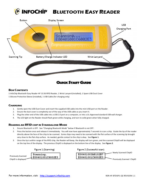
B LUETOOTH E ASY R EADERB OXC ONTENTS1 InfoChip Bluetooth Easy Reader HF 13.56 RFID Reader, 1 Wrist Lanyard (installed), 1 Spare USB Dust Cover 1 Silicone Protective Sleeve (installed), 1 USB Cable (for charging only)C HARGING1. Gently open the USB Dust Cover and insert the supplied USB cable into the mini USB port on the Reader.2. Ensure the dust cover is completely out of the way of the USB cable as you insert it.3. Plug the other end of the USB cable into a USB 2.0 port on a computer, or into a UL-Approved standard USB wall charger.4.The LED light on the Reader should flash green while charging, and turn to solid green when fully charged.R EADING AN RFID CHIP IN S TANDALONE M ODE1. Ensure Bluetooth is OFF. See “Changing Bluetooth Mode” below if Bluetooth is not OFF.2. Press the button once and release it immediately. You will now have approximately 7 seconds to scan a chip. Guide the tip of the readerdirectly above the face of the chip to be scanned. Some chips may need to be scanned with the flat surface of the scanning tip brought very close to the flat chip surface. As needed, gentle contact to the chip is okay. See Figure 1.3. Once the tip is within range of the RFID chip, the Reader will beep, the display will turn green, and the scanned ChipID will be displayedon the top line of the display. The previous ChipID is displayed on the bottom line of the display. See Figure 2.Figure 1 (Scanning)Figure 2 (Successful scan)ButtonBattery/Charge Indicator LED Display ScreenScanning TipWrist LanyardUSB Charging PortQ UICK S TART G UIDENewly Scanned ChipID Previously Scanned ChipIDFor more information, visit: RDR-HF-BTDISP1-QS REVISION 1.1T URNING B LUETOOTH O N AND O FF1. Press and Hold the button until the menu appears, then release the button. See Figure 3.2. Click and Release the button repeatedly until the Bluetooth ON/OFF page is displayed. See Figure 4.3. Now Press and Hold the button to toggle the Bluetooth setting ON or OFF. When Bluetooth is ON, more Bluetooth menu options will beavailable. See Figure 5.Figure 3 (Menu)Figure 4 (Bluetooth OFF) Figure 5 (Bluetooth ON)P RACTICE E NTERING P AIRING C ODES (PIN S )When pairing to a host device, the host device may ask you to enter a pairing code or PIN from 4 to 8 digits in length. Generally you have about 30 seconds to enter this PIN on the Reader. This can be difficult initially, but becomes easy with some practice. We have provided a Practice PIN menu option that will allow you to enter random pairing codes so you can familiarize yourself with the metho d. Let’s practice entering “7654”.1. To get into Practice PIN mode, Press and Hold the button until the menu appears. Then Click and Release the button repeatedly until thePractice PIN menu option is displayed. See Figure 10.2. Press and Hold to enter the Practice Pin mode. (The first digit 0 appears). To change the first digit, click and release the button quicklyand repeatedly (this is called a Short Press) until the desired digit “7” is displayed. See Figure 11.3. To move to the next digit, press and hold the button for more than 0.5 seconds but less than 1 second. This is called a Medium Press.The 2nddigit will show “0”. Short Press until the desired digit “6” is displayed. See Figure 12.4. Medium Press to move to the 3rd digit, then Short Press to until “5” is displayed. Medium Press to move to the 4thdigit, then Short Pressrepeatedly until the desired digit “4” is displayed. See Figure 13.5. Now that your desired “7654” PIN is shown, use a Long Press (press and hold) until the code is accepted. Keep experimenting until youare familiar with the method of entering PINs.Figure 10 (Practice PIN) Figure 11 Figure 12 Figure 13P AIRING TO AH OST D EVICE(P HONE /HANDHELD /L APTOP )The InfoChip Bluetooth Easy RFID Reader appears and acts as a Bluetooth keyboard. It can pair to most devices that accept the Bluetooth keyboard profile without driver software. If you are not in the menu system already, Press and hold the button until the menu appears, then release it.1. Click and Release the button repeatedly to scroll through the menu options. Stop when you arrive at the screen labeled Pair as Keyboard .See Figure 6.2. Press and Hold the button to set the Reader into pairing mode, which should cause the display to flash, indicating the Reader is ready topair. See Figure 7. Now turn on Bluetooth on your host device and begin searching for a device to pair with. Please refer to your device’s manual for instructions on how to turn its B luetooth on and how to place it into pairing mode.3. Once your host device finds the InfoChip keyboard, select it for pairing. Your host device should ask you to enter a pairing code on theReader, which you will have approximately 25 seconds to accomplish. See Figure 8. Please see the section “Practice Entering Pairing Codes ” to successfully accomplish this step. Once you have entered that pairing code successfully on the Reader in the allotted time, the pairing process is complete. See Figure 9. Exit the menu and now your host device should be ready to accept scanned ChipIDs from the Reader. If you did not complete the pairing successfully your device will tell you, and you must repeat steps 1 to 3 above until successful.Figure 6 (Pair as Keyboard) Figure 7 (Pairing) Figure 8 (Pairing PIN) Figure 9 (Pairing Complete)R EADING A C HIP W HILE C ONNECTED TO A H OST D EVICE1. Ensure Bluetooth is turned ON.2. Ensure the Reader has been paired successfully to your host device using the instructions above.3. On your host device, start any application that accepts text input (such as Notes, Email, etc).4.Short Press the button on the Reader. The Reader’s display should read “Bluetooth Trying To Connect” and it should quickly find your host device, at which time the Reader will begin flashing and beeping and trying to scan a chip. You now have approximately 7 seconds to place the tip of the Reader up to the face of the chip to be read. In doing so, the unique ChipID of the scanned chip (which should be similar to E004010014F25431) will be entered at the active cursor location of the host device.For more information, visit: RDR-HF-BTDISP1-QS REVISION 1.1。
《光纤Bragg光栅温度-应变解调仪设计》

《光纤Bragg光栅温度-应变解调仪设计》篇一光纤Bragg光栅温度-应变解调仪设计一、引言随着光纤传感技术的不断发展,光纤Bragg光栅(FBG)作为一种重要的光纤传感器件,在许多领域中得到了广泛的应用。
其能够通过检测反射回来的特定波长光来获取外部环境的温度、应变等信息。
因此,设计一个高性能的光纤Bragg光栅温度/应变解调仪显得尤为重要。
本文旨在探讨光纤Bragg光栅温度/应变解调仪的设计原理、关键技术及实现方法。
二、系统设计原理光纤Bragg光栅温度/应变解调仪的核心原理是利用宽带光源发出的光经过光纤Bragg光栅后,反射回特定波长的光信号,通过解调仪对反射光的波长进行检测,从而推算出外部环境的温度或应变信息。
三、硬件设计(一)光源模块光源模块采用宽带光源,具有较高的稳定性和可靠性。
同时,为提高解调仪的灵敏度,需确保光源的波长范围能够覆盖光纤Bragg光栅的反射波长。
(二)光纤Bragg光栅模块光纤Bragg光栅模块是整个系统的核心部件,其性能直接影响到解调仪的精度和稳定性。
该模块需具备高灵敏度、高分辨率和良好的稳定性。
(三)解调模块解调模块负责检测反射光的波长,并将其转换为温度或应变信息。
该模块需采用高精度的光谱检测技术,如光谱分析仪或高速光谱仪等。
(四)数据处理与输出模块数据处理与输出模块负责将解调模块输出的数据进行处理和转换,以便于用户使用。
该模块需具备高速数据处理能力和友好的人机交互界面。
四、软件设计软件设计是光纤Bragg光栅温度/应变解调仪的重要组成部分,主要包括数据采集、数据处理、数据存储与传输等部分。
软件需具备实时性、稳定性和可扩展性等特点,以适应不同应用场景的需求。
(一)数据采集软件通过与硬件模块的通信接口,实时采集反射光的波长信息。
同时,软件需对采集到的数据进行预处理,如去除噪声、平滑处理等。
(二)数据处理数据处理是软件的核心部分,包括波长到温度/应变的转换、数据校正、数据存储等。
FBG8600光纤光栅测量系统使用说明书

FBG8600 光纤光栅解调仪
使用说明书
北京基康科技有限公司
北京基康科技有限公司 2008 (C)版权所有
第 1 页共 52 页
FBG8600 光纤光栅解调仪使用说明书
【FBG8600 照片】
北京基康科技有限公司 2008 (C)版权所有
第 2 页共 52 页
FBG8600 光纤光栅解调仪使用说明书
目录
1、 FBG8600 光纤传感分析仪简介 ............................................... 4 2、 安全操作说明 ............................................................ 5 3、 工作原理 ................................................................ 7 4、 FBG8600 光纤传感分析仪的系统特点 ......................................... 8 5、 FBG8600 后面板接口说明 ................................................... 8 6、 FBG8600 主要技术指标 ..................................................... 9 7、 传感器的扩充方法 ....................................................... 10 8、 FBG8600 服务器端软件简介 ................................................ 10
光纤光栅静态解调仪使用说明书
武汉中地恒达科技有限公司企业标准ZDHD-QS-JS039-1.0-2020光纤光栅静态解调仪使用说明书2020-6-1实施本说明书由武汉中地恒达科技有限公司编制1.硬件设备说明1.1产品简介FBG-2000是武汉中地恒达科技有限公司研发设计的一款专用监测仪器,配套光纤光栅传感器使用。
专用于桥梁、隧道、大坝、边坡等的工程结构在线监测。
具有多种多功能、操作简单、接口方便,同时适合于用户进行二次开发。
产品采用了先进的技术路线,采集出带宽范围内的海量光谱点,并根据运算规则计算出光谱中峰值的中心位置。
同时结合了工程应用的需要。
系统既提供高精度的波长分辨率,又满足工程环境长期稳定运行的要求。
FBG-2000主机采用优化的数字逻辑进行电路运算处理,可以快速找到中心波长的位置。
同时采用光学标准具进行校准,保证系统温度测量的准确性和稳定性。
其主机设计包括的基本配置:扫描光源,光探测器,电路、软件处理、光路、电源等部分组成,系统最大化地集成了各个模块,使得各模块独立工作,又互相联系,保证了系统的良好的一致性,也方便了用户的使用维修。
钢筋计适用于长期埋设在混凝土结构物内部,测量结构物内部的钢筋应力。
1.2装箱清单光纤光栅解调仪主机x1铝合金包装箱x1电源线x1检测报告x1合格证x1使用说明书x1 1.3产品规格指标1.4产品内部结构示意图外接传感器光学系统电路系统工控机(windows)外接键、鼠、显示器与通讯网络1.5对外接口光纤FC 接口用于连接传感器网口对外通讯AC220V 电源口USB主要用于接鼠标键盘、U 盘VGA 或HDMI 主要用于内置工控机时接显示器1.6相比于同类产品的优势【设备信噪比高】下图为本产品与同行产品的对比,在外接相同传感器、相同条件下运行,本产品的波长白噪声约为±1pm,同行的产品白噪声达到±15pm(对外宣称指标为1pm精度)。
本产品的信噪比符合宣称指标并明显优于市场同类产品。
K-8120 光隔 CAN 总线通讯卡使用说明书.
JP4,JP6:短接,选择 120 欧的终端匹配电阻。
JP5,JP7:短接,CAN 总线接口芯片工作在高速方式,为避免射频干扰,建议使用屏
蔽电缆。
断开,CAN 总线接口芯片工作在限斜率方式,对于较低速度或较短总线,
可使用非屏蔽双绞线或平行线。
5. 状态指示灯:
TX01:COM1 通讯指示灯,发送数据流时,灯闪烁。
//置发送命令
}
接收数据
if(inport(BASE+2)&0x01)==0x01) //查询有无新的有效报文
{
rsr1reg=inport(BASE+20);
//接收相应的数据
rsr2reg=inport(BASE+21);
for(I=0;I<8;I++)
rdb[I]=inport(BASE+22+i);
偏移量改变sja的状态测试出厂测试用10发送标识符1报文名称11发送标识符2数据长度1219发送缓冲区数据场20接收标识符1报文名称21接收标识符2数据长度2229接收缓冲区数据场31时钟驱动器clkout频率选择can传输速率选择表
产品说明书
K-8120 光隔 CAN 总线通讯卡使用说明书
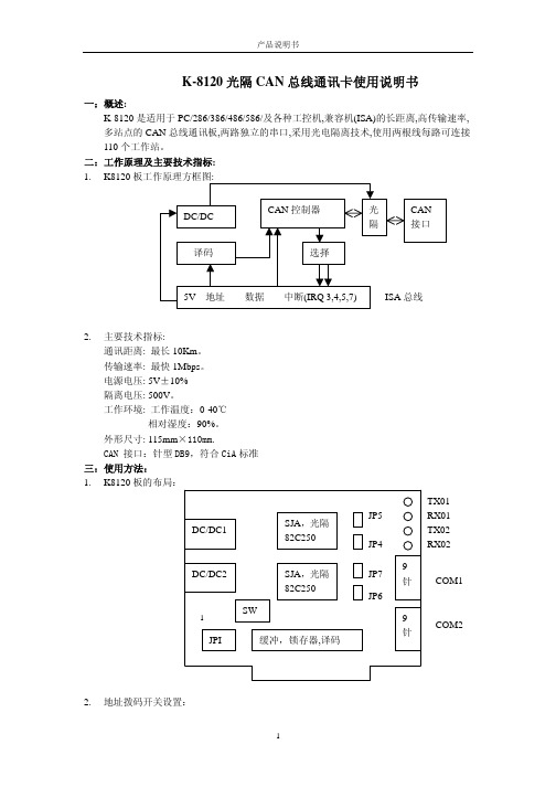
一:概述: K-8120 是适用于 PC/286/386/486/586/及各种工控机,兼容机(ISA)的长距离,高传输速率, 多站点的 CAN 总线通讯板,两路独立的串口,采用光电隔离技术,使用两根线每路可连接 110 个工作站。
10. 编程示例:(TC) if(!CAN_Init(BASE,COMNO,ACR,AMR,BTR0,BTR1,INCT)
printf("Can of Init is fault ! ");
10MHz 5 MHz 功能发生器 (GFG-8210 GFG-8255A) 操作手册说明书
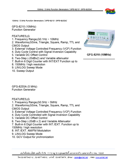
10MHz / 5 MHz Function Generators ( GFG-8210 \ GFG-8255A)Specifications:•10MHz GFG-8210 Specifications:o Maino Frequency Range 0.1Hz ~ 10MHz (8 ranges)o Amplitude >10Vp-p (into 50£[ load)o Impedance 50£[+10%o Attenuator -20dB+1dB x 2o DC Offset <-5V ~ >5V( into 50£[ load)o Duty Control 15% : 85% : 15% to 1MHz Continue variable (square wave only)o Display 6 digits LED displayo---------------------------------------------------------------------------o Sine Waveo Distortion 1% typicalo Flatness + 0.45dB (+5%)o---------------------------------------------------------------------------o Triangle Waveo Linear >98% to 100kHzo----------------------------------------------------------------------------o Square Waveo Symmetry +2%, 1Hz ~ 100kHzo Rise or Fall Time < 35nSo---------------------------------------------------------------------------o CMOS Outputo Max. Frequency 2MHzo Level <4Vpp ~ 14.5Vpp+0.5Vpp adjustableo Rise or Fall Time <120nSo---------------------------------------------------------------------------o TTL Outputo Level >3Vppo Rise or Fall Time <20nSo---------------------------------------------------------------------------o VCFo Input Voltage 0V~10V ¡1V(100 : 1)o Input Impedance 10k£[ ¡0%o---------------------------------------------------------------------------o Sweep Operationo Sweep/Manual Switch selectoro Sweep/Rate >100 : 1 ratio max. and adjustableo Sweep/Time 0.5sec. ~ 30sec. adjustableo Sweep/Mode Lin./Log. switch selectoro Sweep/Out 0V ~ 10+1Vo----------------------------------------------------------------------------o Frequency Countero INT./EXT. Switch selectoro Range 0.1Hz ~ 10MHz (5Hz ~ 150MHz EXT.)o Accuracy Timebase accuracy ¡ counto Timebase ¡Ӳ0ppm (23¢XC¡¢XC) after 30 minutes warm upo Resolution The maximum resolution is 100nHz for 1Hz and 1Hz for 100MHzo Input Impedance 1M£[//150pFo----------------------------------------------------------------------------o Power Source AC 115V/230V¡5%, 50/60Hzo----------------------------------------------------------------------------o Accessories Power cord ¡1,o Instruction manual ¡1,o GTL-101 ¡ 2o----------------------------------------------------------------------------o Dimensions & Weight 251(W) ¡91(H) ¡291(D) mm, Approx. 2.2 kg• 5 MHz GFG-8255A Specifications:o Maino Frequency Range 0.5Hz to 5 MHz (7 ranges)o Amplitude >10Vp-p (into 50£[ load)o Impedance 50£[ +10%o Attenuator -20dB+1dB x 2o DC Offset <-5V ~ >5V (into 50£[ load)o Duty Control 80% : 20% : 80% to 1MHz Continue variable o Display 6 digit LED displayo---------------------------------------------------------------------------o Sine Waveo Distortion <1%, 0.5Hz ~ 100kHzo Flatness <0.3dB, below 500kHz¡F <1dB, below 5MHzo----------------------------------------------------------------------------o Triangle Waveo Linear >98%, 0.5Hz ~ 100kHz¡F >95%, 100kHz ~ 5MHzo---------------------------------------------------------------------------o Square Waveo Symmetry +2%, 1Hz ~ 100kHzo Rise or Fall Time < 50nS at maximum output (into 50£[ load) o----------------------------------------------------------------------------o CMOS Outputo Level 4Vpp+1Vpp ~ 14.5Vpp+0.5Vpp adjustableo Rise or Fall Time <120nSo----------------------------------------------------------------------------o TTL Outputo Level >3Vppo Fan Out 20 TTL loado Rise/Fall Time <25nSo----------------------------------------------------------------------------o VCFo Input Voltage 0V~10V ¡V(100 : 1)o Input Impedance 10k£[ ¡0%o--------------------------------------------------------------------------o GCVo Output Voltage To set the voltage between 0V ~ 2V as per different frequency o----------------------------------------------------------------------------o Sweep Operationo Sweep/Manual Switch selectoro Sweep/Rate 100 : 1 ratio max. and adjustableo Sweep/Time 0.5sec. ~ 30sec. adjustableo Sweep/Mode Lin./Log. switch selectoro----------------------------------------------------------------------------o Amplitude Modulationo Depth 0 ~ 100%o MOD. Frequency 400Hz (INT), DC ~ 1MHz(EXT)o Carrier BW 100Hz ~ 5MHz (-3dB)o EXT Sensitivity <10Vpp for 100% modulationo----------------------------------------------------------------------------o Frequency Modulationo Deviation 0 ~ + 5%o MOD. Frequency 400Hz(INT), DC ~ 20kHz(EXT.)o EXT. Sensitivity <10Vpp for 10% modulationo----------------------------------------------------------------------------o Frequency Countero INT./EXT. Switch selectoro Range 0.5Hz ~ 5MHz (5Hz ~ 150MHz EXT.)o Accuracy Timebase accuracy ¡ Counto Timebase ¡Ӳ0ppm (23¢XC¡¢XC) after 30 minutes warm upo Resolution The maximum resolution is 100nHz for 1Hz and 1Hz for 100MHz o Input Impedance 1M£[//150pFo Sensitivity <35mVrms (5Hz ~ 100MHz)¡F< 45mVrms (100MHz ~ 150MHz)o----------------------------------------------------------------------------o Power Source AC 115V/230V¡5%, 50/60Hzo----------------------------------------------------------------------------o Accessories: Power cord ¡1, Instruction manual ¡1, GTL-101 ¡ 2o----------------------------------------------------------------------------o Dimensions & Weight 251(W) ¡91(H) ¡291(D) mm, Approx. 2.4kg。
光纤光栅便携式解调仪使用及注意事项

宿州市金鼎安全技术研究所文件编号:CZ002 第 1 页共 1 页
仪器使用注意事项
一、主机
1.由于使用激光器件,请勿频繁开关机。
2.可以使用触摸屏或USB鼠标进行操作。
请勿使用尖锐物体刮擦触摸屏表面。
USB口可以连接鼠标或U盘。
请注意:某些USB设备因耗电量大,在本机上可能导致识别不出,属于正常情况,请更换其他设备。
3.锂电池:使用过后,即可充电。
在“欠电”灯亮起后,请及时为锂电池充电。
长期不用每隔15-30天进行一次充电,以保持电池的良好性能。
二、电学接口
1.接口,类型为FC/APC。
接口不用时,请及时旋盖避灰。
2.并口,该接口因为粉尘污染可能导致影响测量,可使用无尘擦拭纸或者棉签蘸取酒精后进行清理。
光学接口有不可见激光发出,请注意防护。
3.使用直流稳压电源可进行充电。
充电状态下仍可正常使用。
- 1、下载文档前请自行甄别文档内容的完整性,平台不提供额外的编辑、内容补充、找答案等附加服务。
- 2、"仅部分预览"的文档,不可在线预览部分如存在完整性等问题,可反馈申请退款(可完整预览的文档不适用该条件!)。
- 3、如文档侵犯您的权益,请联系客服反馈,我们会尽快为您处理(人工客服工作时间:9:00-18:30)。
FBG8210 便携式解调仪 使用手册
北京基康科技有限公司
1998-2008 (C) All rights reserved. Page 1/73
BGK-FBG8210 便携式解调仪使用手册
图片:BGK-FBG-8210 便携式解调仪
1998-2008 (C) All rights reserved. Page 2/73
1998-2008 (C) All rights reserved. Page 4/73
BGK-FBG8210 便携式解调仪使用手册
1. 概述
光纤传感技术是 20 世纪 70 年代伴随光通信技术的发展而迅速发展起来的一种新型传 感技术。作为被测信号载体的光波和作为光波传播媒介的光纤,具有一系列独特的、其他 载体和媒介难以比拟的优点:光纤本身不带电、体积小、质量轻、易弯曲、抗电磁干扰、 抗辐射性能好,特别适用于易燃、易爆、空间受严格限制和强电磁场等恶劣环境下使用。
6.3 数据的测量及存储 ............................................................... 40 6.3.1 连续自动测量工作模式时的测量及存储..........................................40 6.3.2 单次手动测量工作模式时的测量及存储..........................................41 6.3.3 测量过程中出现的测量故障....................................................42
WARNING:使用时请保持仪器的稳定。 CAUTION:请不要将本仪器直接置于下雨或太潮湿的环境中。
1998-2008 (C) All rights reserved. Page 5/73
BGK-FBG8210 便携式解调仪使用手册 激光安全标志。提醒用户安全正确操作。
提醒用户根据使用手册正确操作。
6.5.1 软件安装....................................................................43 6.5.1.1 USB 接口驱动程序的安装.................................................. 43 6.5.1.2 应用软件安装............................................................ 44
注意: 激光安全符号已经标在仪器上,您可以在机箱的前面板找到它。
如果设备的激光光源出现了故障,请您一定要与我们联系进行维修和重新标定。用户 请勿私自打开机壳。 WARNING:此光源发出的光是看不到的,但是它可能会对您的视力造成伤害,请避 免激光直接射入眼睛。
1998-2008 (C) All rights reserved. Page 6/73
6.2 菜单功能 ....................................................................... 15 6.2.1 菜单界面....................................................................15 6.2.2 工作模式界面................................................................16 6.2.3 传感器类型界面..............................................................18 6.2.4 参数设置界面................................................................19 6.2.4.1 锚索计设置界面.......................................................... 19 6.2.4.2 通用光缆设置界面........................................................ 26 6.2.5 历史记录界面显示............................................................28 6.2.6 关机设置界面显示............................................................35 6.2.7 语言选择界面显示............................................................36 6.2.8 设置时间界面显示............................................................38 6.2.9 背光设置界面显示............................................................39
警告有可能遭到电击。
警告用户如果不严格的按照操作手册上步骤操作,可能会导致仪 器损坏。
提示用户如果不严格遵守使用手册上的操作规则,可能会给自己 的身体甚至生命带来潜在的危害
光源安全参数: 仪器内置宽带光源,其具体参数如下:
光源类型 等级 输出光功率 波长
SLED、ASE Ⅲa 3mw 1525~1565nm
1998-2008 (C) All rights reserved. Page 3/73
BGK-FBG8210 便携式解调仪使用手册
附录二 光纤测温的现状 ............................................................. 70 附录三 基本概念和常用术语 ......................................................... 71 附录四 锚索计计算公式及其参数 ..................................................... 72 附录五 菜单结构树状图 ............................................................. 73
FBG8210 便携仪是一款基于光纤通讯领域中成熟的 MEMS 可调滤波技术,具有高精 度,高分辨率,多功能的解调读数仪器。
便携仪采用 LCD 屏直观显示,且操作简单、界面友好,内置锂电池,具有数据存储、 数据查询等功能,还可通过 RS232 将数据上传给 PC 机,机壳采用 ABS 工程塑料,重量轻、 抗冲击、抗变形,对恶劣环境适应好,尤其适合需要ห้องสมุดไป่ตู้量使用光纤传感产品,并需要重复 测量的应用场合。
6.4 声音提示功能 ................................................................... 42 6.5 上位机通讯 ..................................................................... 43
BGK-FBG8210 便携式解调仪使用手册 CAUTION:使用不干净或已经损坏的连接头可能会损坏其它的连接头。 CAUTION:请不要将连接头拧的太紧,这样可能会造成连接头损坏。 CAUTION:设备前面板的光学接口是 FC/APC 接口,连接时请保证连接头匹配,否则 会造成连接头损坏甚至导致模块损坏。 CAUTION:随机附带多条长 0.5 米长的跳线,使用时请将此跳线接到仪器的光学接口, 在一般情况下,请不要将此跳线拆下,避免污染设备光口。 请按以下步骤清洁光学接头: 1. 取一块干净的酒精棉。 2. 滴上少量酒精,然后将多余的酒精挤出。 3. 打开光学接头的保护帽。 4. 将光学接头端面朝下按在酒精棉上平移,重复几次,然后新取一块酒精棉擦干。
6. 软件操作规范 ...................................................................... 12
6.1 开机欢迎界面及主界面显示........................................................ 12 6.1.1 开机欢迎界面显示............................................................12 6.1.2 主界面显示..................................................................13 6.1.2 .1 主界面分类............................................................. 13 6.1.2 .2 主界面显示的内容....................................................... 13
5. 硬件操作规范 ...................................................................... 10
5.1 面板说明 ....................................................................... 10 5.2 供电方式 ....................................................................... 12
6.5.2 上位机软件功能介绍..........................................................45 6.5.2.1 读波长模式 ............................................................. 46 6.5.2.2 读光谱模式 ............................................................. 55