优派PJD7820HD
Digilent Pmod MTDS 2.8 英寸触摸屏显示器说明书
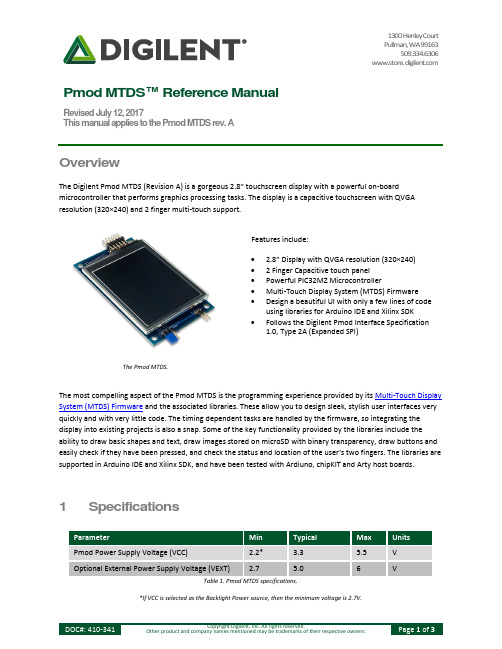
1300 Henley CourtPullman, WA 99163509.334.6306www.store. Pmod MTDS™ Reference ManualRevised July 12, 2017This manual applies to the Pmod MTDS rev. AOverviewThe Digilent Pmod MTDS (Revision A) is a gorgeous 2.8” touchscreen display with a powerful on-board microcontroller that performs graphics processing tasks. The display is a capacitive touchscreen with QVGA resolution (320×240) and 2 finger multi-touch support.Features include:∙ 2.8” Display with QVGA resolution (320×240)∙ 2 Finger Capacitive touch panel∙Powerful PIC32MZ Microcontroller∙Multi-Touch Display System (MTDS) Firmware∙Design a beautiful UI with only a few lines of codeusing libraries for Arduino IDE and Xilinx SDK∙Follows the Digilent Pmod Interface Specification1.0, Type 2A (Expanded SPI)The Pmod MTDS.The most compelling aspect of the Pmod MTDS is the programming experience provided by its Multi-Touch Display System (MTDS) Firmware and the associated libraries. These allow you to design sleek, stylish user interfaces very quickly and with very little code. The timing dependent tasks are handled by the firmware, so integrating the display into existing projects is also a snap. Some of the key functionality provided by the libraries include the ability to draw basic shapes and text, draw images stored on microSD with binary transparency, draw buttons and easily check if they have been pressed, and check the status and location of the user's two fingers. The libraries are supported in Arduino IDE and Xilinx SDK, and have been tested with Ardiuno, chipKIT and Arty host boards.1 SpecificationsParameter Min Typical Max UnitsPmod Power Supply Voltage (VCC) 2.2* 3.3 5.5 VOptional External Power Supply Voltage (VEXT) 2.7 5.0 6 VTable 1. Pmod MTDS specifications.*If VCC is selected as the Backlight Power source, then the minimum voltage is 2.7V.1.1 Pinout Table DiagramHeader J1Pin Signal Description1 CS Chip Select2 MOSI Master Out Slave In3 MISO Master In Slave Out4 SCLK Serial Clock5 GND Power Supply Ground6 VCC Power Supply (3.3V/5V)7 NC Not Connected8 RESET Active-Low Reset9 NC* Not Connected10 NC* Not Connected11 GND Power Supply Ground12 VCC Power Supply (3.3V/5V)Table 2. Header J1.* Pins 9 and 10 of J1 are attached to the PIC32, but are not used by the firmware and should be treated as if they are not connected.Header J2 (External Backlight Power)Pin Signal Description1 VEXT External Power SupplyPositive Connection2 GND Power Supply GroundTable 3. Header J2 (External Backlight Power)JumpersName State DescriptionJP1 EXT Use External power supplyattached to J2 to powerBacklightJP1 VCC Use VCC from Pmodconnector to power BacklightTable 4. Jumpers.1.2 Physical DimensionsThe pins on the pin header are spaced 100 mil apart. The PCB is 3.45 inches long on the sides parallel to the pins on the pin header and 2.00 inches long on the sides perpendicular to the pin header.2 Functional DescriptionThe Pmod MTDS has an on-board PIC32MZ microncontroller that is running the MTDS firmware. To communicate with the device, you must use the MTDS and MyDisp libraries available and documented on the MTDS resource center. Arduino and chipKIT host boards should use the Arduino IDE libraries, and Xilinx FPGA or Zynq based hostboards should use the Pmod MTDS IP core and the libraries included with it. For information on downloading and using the Pmod MTDS IP core see the Using Pmod IPs Tutorial. After exporting to Xilinx SDK, follow the README.txt guide included in the examples folder.JP1 is used to select how to power the display's backlight. A single jumper should be loaded across 2 of the three pins in order to select the power source. When the jumper is loaded across the bottom 2 pins the backlight is powered by VCC on the Pmod connector, and when it is loaded across the top two pins the backlight is powered by an external power supply attached to J2. This external power supply must meet the minimum and maximum voltage requirements outlined in the Specifications table above.The microSD connector allows the MTDS firmware to draw and save images to an attached microSD card. In order to work properly, the microSD card must be formatted as FAT32. Image files should be saved as Windows Bitmap files (.bmp). For more information see the MTDS documentation available on the MTDS resource center.2.1 Serial CommunicationThe Pmod MTDS communicates with the host board via the SPI protocol; however, the implementation of this physical interface is handled by the MTDS libraries and it is not necessary to understand the details for its use.2.2 Quick UsageTo get started with the Pmod MTDS quickly, go to the MTDS resource center and follow the instructions found there for your host platform.。
BenQ显示器说明书

免责声明
BenQ Corporation 对于本文档的内容不提供任何明示或隐含的陈述或担保,特别是针对特 殊目的的适销性和适用性不提供任何担保。另外,BenQ Corporation 保留修订本出版物和 随时修改本文档内容而不需通知任何人的权利。
请遵照安全说明使显示器达到最佳性能和最长使用寿命
电源安全性
您应调整显示器位置和显示屏角度,以使来自其它光源不 需要的反射达到最小。
6 如何安装显示器硬件
2. 连接 PC 视频电缆。
切勿在一台 PC 上同时使用 DVI-D 电缆和 D-Sub 电缆。 仅在两根电缆连接到两台配备适当视频系统的 PC 的情况 下才可同时使用这两种电缆。
将 DVI-D 电缆的一端连接到显示器 DVI-D 输入插口, 然后将另一端连接到电脑上的 DVI-D 端口。(可选)
4 使用入门
2. 开始了解您的显示器
正视图
后视图
1. 交流电源输入插孔 2. DVI-D 输入插口 3. D-Sub 输入插口
开始了解您的显示器 5
3. 如何安装显示器硬件
如果电脑已打开,您必须在继续安装之前先关闭电脑。 在看到确实指示之前切勿插入或打开显示器电源。
1. 连接显示器底座。
请小心以防损坏显示器。 将屏幕表示置于诸如订书机或鼠 标等物上,会使玻璃损碎或损坏 LCD 的底基,该损坏不 属保修范围。 在书桌上滑动或刮擦显示器会乱伤或损坏显 示器的包围物和控制器。
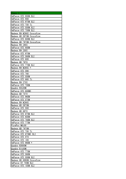
2015年笔记本显卡性能排名大全(包含intel Iris显卡、已标识intel和手机显卡)
ViewSonic PJ-WPD-200高速数据流量USB无线适配器说明书
Required Software
Windows XP / 7 / 8, MAC
64 bit/128 bit WEP, TKIP, AES, WPA, WPA2
USB 2.0
1.14 x 0.28 x 0.63 in. / 29 x 7 x 16 mm 5.12 x 0.95 x 5.91 in. / 130 x 25 x 150 mm
PJ-WPD-200
2.4GHz ISM Band
IEEE 802.11b: DSSS (Direct Sequence Spread Spectrum) IEEE 802.11g/n: OFDM (Orthogonal Frequency Division Multiplexing)
Ad hoc, Infrastructure
Specifications
PART # FREQUENCY BAND
SPREAD SPECTRUM
OPERATION MODE OS SUPPORT SECURITY INTERFACE DIMENSIONS (W X H X D)
WEIGHT
Physical Packaging
Net Gross
USB Wireless Adapter
High-speed Data Streaming
PJ-WPD-200
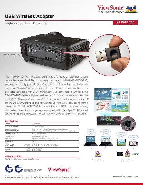
Projector PJ-WPD-200 USB wireless adapter provides added convenience and flexibility to your projection needs. With the PJ-WPD-200, you can wirelessly project from Windows® or Mac laptops, and you can use your Android™ or iOS devices to wirelessly stream content to a projector. Equipped with 2T2R MIMO, and support for up to 300Mbps, the PJ-WPD-200 delivers high-speed and robust data transmission via the IEEE 802.11b/g/n protocol. In addition, the portable and compact design of the PJ-WPD-200 provides an easy way for users to wirelessly connect their projectors. The PJ-WPD-200 is compatible with USB 2.0, most laptops, and select ViewSonic projectors equipped with ViewSync™ Advanced Connect™ Technology (ACT), as well as select ViewSonic PLED models.
电脑配置

处理器
英特尔 Pentium(奔腾) G2020 @ 2.90GHz 英特尔 Pentium(奔腾) D 2.80GHz 英特尔 Celeron(赛扬) 420 @ 1.60GHz 英特尔 Pentium(奔腾) 4 3.06GHz 英特尔 Pentium(奔腾) G2020 @ 2.90GHz 英特尔 Pentium(奔腾) 双核 E5300 @ 2.60GHz 英特尔 Pentium(奔腾) 双核 E5400 @ 2.70GHz 英特尔 Celeron(赛扬) E3500 @ 2.70GHz 英特尔 Pentium(奔腾) 4 2.66GHz 英特尔 Pentium(奔腾) D 3.00GHz 英特尔 Celeron(赛扬) 420 @ 1.60GHz 英特尔 Celeron(赛扬) G530 @ 2.40GHz 英特尔 Pentium(奔腾) 双核 E5300 @ 2.60GHz 英特尔 Celeron(赛扬) 430 @ 1.80GHz 英特尔 Pentium(奔腾) 4 2.66GHz 英特尔 Celeron(赛扬) 420 @ 1.60GHz 英特尔 第二代酷睿 i3-2350M @ 2.30GHz 双核 英特尔 Celeron(赛扬) B830 @ 1.80GHz 双核 英特尔 Celeron(赛扬) E3500 @ 2.70GHz 双核 英特尔 第二代酷睿 i3-2350M @ 2.30GHz 双核 英特尔 Celeron(赛扬) E3500 @ 2.70GHz 双核 英特尔 Celeron(赛扬) B830 @ 1.80GHz 双核 英特尔 第二代酷睿 i3-2350M @ 2.30GHz 双核 英特尔 第三代酷睿 i3-3110M @ 2.40GHz 双核 英特尔 Celeron(赛扬) 430 @ 1.80GHz 英特尔 Celeron(赛扬) 420 @ 1.60GHz AMD Sempron(闪龙) LE-1300 英特尔 Pentium(奔腾) 4 2.66GHz 英特尔 Celeron(赛扬) G530 @ 2.40GHz 英特尔 Celeron(赛扬) E3500 @ 2.70GHz 英特尔 Pentium(奔腾) G2020 @ 2.90GHz 英特尔 Pentium(奔腾) 4 2.66GHz 英特尔 Pentium(奔腾) 4 2.66GHz
BG-UHD-DA1X16 HDMI V2.0 1x16 分裂器分辨率下调与AOC支持用户手册说明书
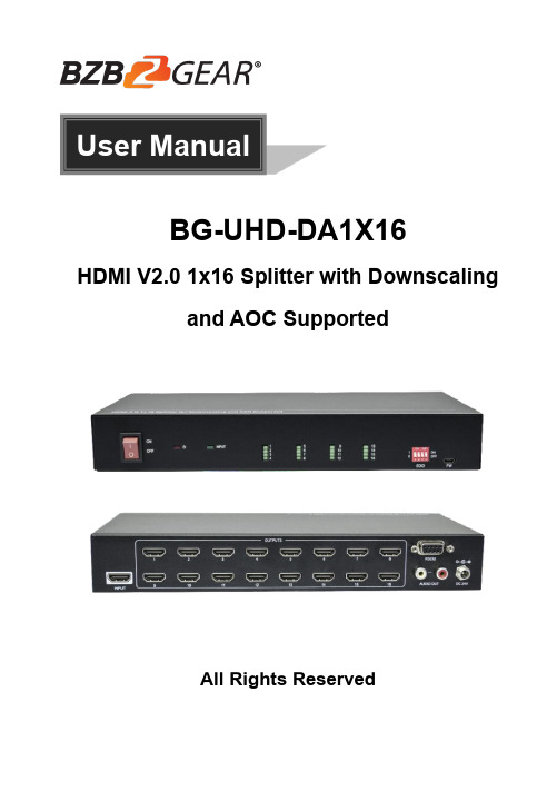
User ManualBG-UHD-DA1X16HDMI V2.0 1x16 Splitter with Downscalingand AOC SupportedAll Rights ReservedTable of Contents1. Product Introduction (1)1.1 Features (1)1.2 Package List (1)2. Specification (2)3. Panel Description (4)3.1 Front Panel (4)3.2 Rear Panel (4)4. System Connection (5)5. DIP Switch Operation (6)6. RS232 Control (7)6.1 System Commands (7)6.2 Setting Commands (8)7. Firmware Upgrade (9)8. Warranty (10)9. Mission Statement (10)1. Product IntroductionThank you for choosing our HDMI V2.0 1x16 Splitter, which can distribute one HDMI input to sixteen HDMI outputs. The splitter supports 4K signals up to 4K@60Hz 4:4:4, HDR 10, Dolby Vision and features advanced EDID management option using 4-pin DIP switch on the front panel of the unit. It also supports downscaling so a 4K video input can automatically be down scaled to a 1080p output when connecting a display that only supports resolution up to 1080p. Stereo analog L/R audio output is provided for audio de-embedding from HDMI input and the splitter supports CEC and RS232 control.1.1 FeaturesHDMI V2.0, 4K@60Hz 4:4:4 8bit, HDR 10, Dolby Vision.HDCP 2.2 compliant.Compatible with HDMI AOC cable, provides up to 5V100mA power on each output.Auto 4K to 1080p downscaling.Stereo analog L/R audio output for audio de-embedding from HDMI input.Smart EDID management and HDCP management.CEC and RS232 control.1.2 Package List1x 1x16 Splitter2x Mounting Ears with 4 Screws4x Plastic Cushions1x RS232 Cable (Female DB9 to Male DB9)1x Power Adapter (24V DC, 1.25A)1x User ManualNote: Please contact your distributor immediately if any damage or defect in the components is found.2. SpecificationVideoInput (1) HDMIInput Connector (1) Type-A female HDMIInput Video Resolution Up to 4K@60Hz 4:4:4 8bit, HDR10, Dolby Vision Output (16) HDMIOutput Connector (16) Type-A female HDMIOutput Video Resolution Up to 4K@60Hz 4:4:4 8bit, HDR10, Dolby Vision, supports 4K to 1080p down-scaling.HDMI Output Supports up to 5V100mA power for AOC cable. HDMI Standard V2.0HDCP Version 2.2HDMI Audio Signal LPCM 7.1 audio, Dolby Atmos®, Dolby® TrueHD, Dolby Digital® Plus, DTS:X™, and DTS-HD® Master Audio™ pass-through.Analog Audio OutputOutput (1) AUDIOOutput Connector (1) RCA (L+R) Frequency Response 20Hz~20kHz, ±1dBMax output level 2.0Vrms ± 0.5dB. 2V=16dB headroom above-10dBV (316mV) nominal consumer line level signalTHD+N < 0.05%, 20Hz~20kHz bandwidth, 1kHz sine at 0dBFS level (or max level)SNR > 80dB, 20Hz~20kHz bandwidthCrosstalk isolation < -80dB, 10kHz sine at 0dBFS level (or max level before clipping) L-R level deviation < 0.05dB, 1kHz sine at 0dBFS level (or max level before clipping) Output load capability 1Kohm and higher (supports 10x paralleled 10Kohm loads) Noise Level- 80dBControl PartControl Port(1) EDID Switch, (1) FW, (1) RS232Control Connector(1) 4-pin DIP switch, (1) Micro-USB, (1) Female DB9GeneralBandwidth18GbpsOperation T emperature-5℃~ +55℃Storage Temperature-25℃~ +70℃Relative Humidity10%-90%External Power Supply Input: AC 100~240V, 50/60Hz; Output: 24V DC 1.25APower Consumption 26W (Max)Dimension (W*H*D) 268mm x 40mm x 125mmNet Weight 1.14KGVideo Resolution Down-scaling:The splitter supports video resolution downscaling, the 4K input can be automatically degraded to 1080p output for compatibility with 1080p display, shown in the below chart.Input Output#Resolution Refresh ColorSpaceDownscale1080p Specs13840x216060Hz4:4:4Support1080p@60Hz 4:4:4 23840x216050Hz4:4:4Support1080p@50Hz 4:4:4 33840x216030Hz4:4:4Support1080p@30Hz 4:4:4 43840x216025Hz4:4:4Support1080p@25Hz 4:4:4 53840x216024Hz4:4:4Support1080p@24Hz 4:4:4 63840x216023Hz4:4:4Support1080p@23Hz 4:4:4 73840x216060Hz4:2:0Support1080p@60Hz 4:4:4 83840x216050Hz4:2:0Support1080p@50Hz 4:4:4 93840x216030Hz4:2:0Support1080p@30Hz 4:4:4 103840x216025Hz4:2:0Support1080p@25Hz 4:4:4 113840x216024Hz4:2:0Support1080p@24Hz 4:4:4 123840x216023Hz4:2:0Support1080p@23Hz 4:4:43. Panel Description3.1 Front Panel① POWER SWITCH: Power on/off the splitter.② POWER LED: Illuminates red when the device is powered on. ③ INPUT LED: Illuminates green when there is HDMI input.④ OUTPUT LEDs (1~16): Illuminates green when there is HDMI output on thecorresponding channel. ⑤ EDID: 4-pin DIP switch for EDID setting and HDCP mode selection. Please refer tothe chapter DIP Switch Operation for more details. ⑥ FW: Micro-USB port for firmware upgrade.3.2 Rear Panel① INPUT: Connect HDMI source.② OUTPUTS: Total sixteen HDMI outputs to connect HDMI displays.③ AUDIO OUT: Connect audio device (e.g. Amplifier) for audio de-embedding fromHDMI input. ④ RS232: Connect control device (e.g. PC) to control the splitter by sending RS232commands. ⑤ DC 24V: DC connector for the power adapter connection.123456123454. System ConnectionThe following diagram illustrates the typical input and output connection of the splitter:Amplifier4K TV4K1080p TV1080p4K TV4K1080p TV1080pHDMI:RS232:Audio:Blue-Ray Central Control System5. DIP Switch OperationThe 4-pin DIP switch on the front panel of the unit is used for EDID management and HDCP management. It represents “0” when in the lower (OFF) position, and it represents “1” while putting the switch in the upper (ON) position.Switch 1~3 are used for EDID setting. The switch status and its corresponding setting are shown at the below chart.Switch Status(PIN 1~3)EDID Value123000Obtains EDID from the first detected display starting at HDMI OUT1>OUT2>.........>OUT16.0011920x1080@60Hz 8bit Stereo0101920x1080@60Hz 8bit High Definition Audio0113840x2160@30Hz 8bit Stereo Audio1003840x2160@30Hz Deep Color High Definition Audio1013840x2160@60Hz Deep Color Stereo1103840x2160@60Hz Deep Color HDR LPCM 6CHSwitch 4 is used for HDCP setting. The switch status and its corresponding setting are shown at the below chart.Switch 4 Status HDCPOFF (0)Automatically follows the HDCP version of display device. When display device has no HDCP, if source device have no HDCP content, the video output has no HDCP content; if source device has HDCP content, there are no video output.ON (1)Automatically follows the HDCP version of source device. Note: The factory default switch status is “0000”, and it needs to be set to “1111” when enable RS232 control to set EDID and HDCP.6. RS232 ControlConnect the RS232 port to control device (e.g. PC) with RS232 cable. The splitter can be controlled by sending RS232 commands.RS232 CommandsThe command lists are used to control the splitter. The RS232 control software (e.g. docklight) needs to be installed on the control PC to send RS232 commands.After installing the RS232 control software, please set the parameters of COM number, bound rate, data bit, stop bit and the parity bit correctly, and then you are able to send command in command sending area.Baud rate: 9600Data bit: 8Stop bit: 1Parity bit: noneNote:All commands need to be ended with “<CR><LF>”.In the commands, “[”and “]” are symbols for easy reading and do not need to be typed in actual operation.Type the command carefully, it is case-sensitive.6.1 System CommandsCommand Description Command Example and Feedback>GetFirewareVersion Get firmware version. <V1.0.0>SetFactoryReset Reset to factory default. <FactoryReset_True >SetReboot System reboot. <Reboot_EN>SetHelp [Param] Get the command details.[Param]= Any command.>SetHelpSetHdcpActiveMode<Set the HDCP bypass fromSRC or SINK>SetHdcpActiveModeParamParam = Src,SinkSrc - Active by srcSink - Active by Sink6.2 Setting CommandsCommand Description Command Example and Feedback>SetUpdateEdid Upload user-defined EDID. The EDIDDIP switch must be set as “1111”.<User edid ready,Pleasesend edid data in 10s.<SetUpdateEdid_True/False/<Time out to send edid>SetInPortEdid [Param] Set the EDID to [Param].[Param]=0~7.0 - BYPASS1 - 1920x1080@60 8bit Stereo2 - 1920x1080@60 8bit High DefinitionAudio3 - 3840x2160@30Hz 8bit Stereo Audio4 - 3840x2160@30Hz Deep Color HighDefinition Audio5 - 3840x2160@60Hz Deep ColorStereo Audio6 - 3840x2160@60Hz Deep Color HDRLPCM 6CH7 - USER EDIDThe EDID DIP switch should be set as“1111”.>SetInPortEdid 0<InPortEdid 0>GetInPortEdid Get the EDID. <InPortEdid 0>SetHdcpActiveMode [Param] Set the HDCP active mode.[Param]=Src, SinkSrc - Active by Src. Follow source.Sink - Active by Sink. Follow display.Note: The EDID switch must bes witched to “1111” before sending thecommand.>SetHdcpActiveMode Src<HdcpActiveMode Src>GetHdcpActiveMode Get the HDCP active mode. <HdcpActiveMode Src>SetVideoOutput [Param1],[Param2] Enable or disable video output.[Param1]=1~16. Output port.[Param2]=EN, DisDis - DisableEn - Enable>SetVideoOutput 1,EN<VideoOutput 1 True>GetVideoOutput Get video output status.>GetVideoOutput 1[Param] [Param]=1~16.Output port.<VideoOutput 1 True>SetAutoDownScaler [Param] Enable/disable 4K to 1080p down-scaling function.[Param]=EN, DisDis - DisableEn - Enable>SetAutoDownScaler EN<AutoDownScaler True>GetAutoDownScaler Get the on-off status of down-scalingfunction.<AutoDownScaler True>SetRS232Baudrate [Param] Set the baud rate to [Param].[Param]=1~71 - 1152002 - 576003 - 384004 - 192005 - 96006 - 48007 - 2400>SetRS232Baudrate 1<RS232Baudrate 1>GetRS232Baudrate Get the RS232 baud rate. <RS232Baudrate 17. Firmware UpgradePlease follow the below steps to upgrade firmware by the Micro-USB port:1) Prepare the latest upgrade file (.bin) and rename it as “FW_MV.bin” on PC.2) Power off the splitter and connect the Micro-USB (FW) port of splitter to the PC withUSB cable.3) Power on the splitter and then the PC will automatically detect a U-disk named of“BOOTDISK”.4) Double-click to open the U-disk, a file named of “READY.TXT” will be showed.5) Directly copy the latest upgrade file (.bin) to the “BOOTDISK” U-disk.6) Reopen the U-disk to check whether there is a filename “SUCCESS.TXT”, if yes,the firmware was updated successfully, otherwise, the firmware updating is fail, the name of upgrade file (.bin) should be confirmed again, and then follow the above steps to update again.7) Remove the USB cable and reboot the splitter after firmware upgrade.8. WarrantyBZBGEAR wants to assure you peace of mind. We're so confident in the quality of our products that along with the manufacturer's one-year limited warranty, we are offering free second-year warranty coverage upon registration*!Taking advantage of this program is simple, just follow the steps below:1. Register your product within 90 days of purchase by visiting/warranty.2. Complete the registration form. Provide all necessary proof of purchase details, including serial number and a copy of your sales receipt.Forquestions,**************************************************.For complete warranty information, please visit /warranty or scan the QR code below.*Terms and conditions apply. Registration is required.9. Mission StatementBZBGEAR manifests from the competitive nature of the audiovisual industry to innovate while keeping the customer in mind. AV solutions can cost a pretty penny, and new technology only adds to it. We believe everyone deserves to see, hear, and feel the advancements made in today’s AV world without having to break the bank. BZBGEAR is the solution for small to medium-sized applications requiring the latest professional products in AV.We live in a DIY era where resources are abundant on the internet. With that in mind, our team offers system design consultation and expert tech support seven days a week for the products in our BZBGEAR catalog. You’ll notice comparably lower prices with BZBGEAR solutions, but the quality of the products is on par with the top brands in the industry. The unparalleled support from our team is our way of showing we care for every one of our customers. Whether you’re an integrator, home theater enthusiast, or a do-it-yourselfer, BZBGEAR offers the solutions to allow you to focus on your project and not your budget.。
平民级超跑上手游戏悍将AS27 UC-PRO电竞显示器

平民级超跑上手游戏悍将AS27 UC-PRO电竞显示器作者:来源:《新潮电子》2020年第03期相信經常关注电竟显示器的玩家对圈内流传的“四大金刚”并不陌生。
就算不清楚也有所耳闻。
所谓“四大金刚”其实是指显示器的硬件参数:工44HZ及以上的刷新率、2.5K分辨率、G-SYNC技术、IPS面板。
在当时又正好有四款产品具备这样的参数要求。
分別是华硕PG279Q、AOCAG271QG、掠夺者XB271HUbmiprZ、优派XG2703-Gs。
这样“四大金刚”就开始流传开来。
以现在来看。
这些参数虽然已经算不上顶级。
但是也并不落伍。
不过取而代之的是更高端的4K@144HZ电竟显示器。
在2018年。
具备4K@144HZ的电竞显示器还只有ROG PG27UQ和ACER X27两款代表产品。
价格更是高高在上。
近两万元的售价着实不便宜。
堪称电竟显示器中的“超跑”。
时隔一年。
由于生产成本的逐渐下降。
4K@144HZ的电竟显示器开始多了起来。
像我们本期体验的游戏悍将AS27UC-PRO就是其中之一。
可以说是平民级“超跑”。
相信很多朋友跟我一样,对游戏悍将的印象还停留在机箱、电源产品线上、游戏悍将涉足显示器领域的时间的确不长。
这款AS27UC-PRO是旗下首款27英寸4K电竞显示器。
同时也是旗下的一款高端电竞显示器。
对于这款显示器,相信游戏悍将对它寄予了很大的期望。
那么实际表现如何?我们将对它的里里外外进行全面的解析、点竞化的外观设计既然定位于电竞显示器,那么在外观上就要给入电竞的气息、游戏悍将A$27UC-PRO的整体外观设计采用了黑色的外观,在底座上、支架提手上辅以红色进行点缀。
这种红黑式的配色,似乎有一种战斗的味道、AS27UC-PRO的整体设计看上去比较清爽、千练,不像其他电竞显示器有激进的设计感。
AS27UC-PRO采用的是人体工学支架,支架支持上下升降和旋转调节。
帮助玩家找到最适合自己的姿勢、同时。
AS27UC-PRO也支持用户安装第三方支架,孔位规格为75mmx75mm。
Dell 1708FP平面顯示器使用手冊说明书
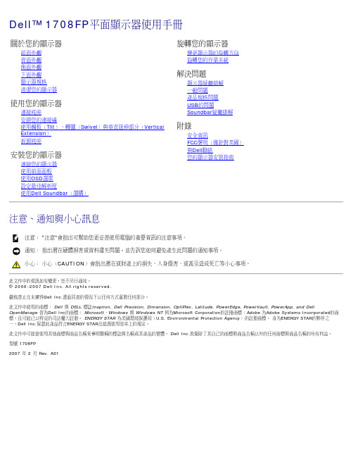
前面外觀背面外觀下面外觀側面外觀顯示器規格清潔您的顯示器1.視訊輸入選擇2.OSD功能表/選擇按鍵3.亮度和對比/向下(-)按鍵4.自動調整(Auto Adjust)/向上(+)按鍵5.電源鍵(含電源指示燈)背面外觀1VESA安裝孔(100mm)(位於連接的底座後用來架設顯示器。
面)2序號條碼標籤若您需要與Dell聯絡以取得技術支援,請參考此標籤。
3安全鎖槽使用安全鎖與此鎖槽來保護您的顯示器。
4Dell Soundbar安裝托架連接選購的Dell Soundbar。
5管理等級標籤列出管理認證。
6底座移除按鍵按下此按鍵可鬆開底座。
7連接線管理孔請將連接線穿過此孔,以便管理連接線。
8鎖定/鬆開按鍵將顯示器向下按,按下按鍵來鬆開顯示器,然後將顯示器抬高至想要的高度。
下面外觀1電源連接接頭插入電源線。
2Dell Soundbar電源接頭連接Soundbar(選購)的電源線。
3DVI接頭連接電腦的DVI連接線。
4VGA接頭連接電腦的VGA連接線。
5USB上游接頭將顯示器隨附的USB連接線連接至顯示器與電腦。
連接好連接線之後,您便可以使用顯示器側面與下方的USB接頭。
6USB接頭連接您的USB裝置。
注意:只有在連接線連接至電腦與顯示器的USB上游接頭之後您才能使用此接頭。
側面外觀左側右側顯示器規格電源管理模式若您的個人電腦上已安裝符合VESA的DPM?規格的顯示卡或軟體,此顯示器便可以在未使用時自動降低其耗電量。
這指的便是'省電模式(Power Save Mode 或其他輸入裝置輸入,顯示器便會自動恢復正常運作。
下面表格列出了此自動省電功能的耗電量與訊號指示:VESA模式水平同步視訊電源指示燈耗電量正常運作(搭配Dell Soundbar與USB啟用的情況下)使用中使用中綠色75 W(最大)正常運作使用中使用中綠色35 W(典型)使用中-關閉模式停用中關閉-注意: OSD只有在'正常運作'模式中才有作用。
- 1、下载文档前请自行甄别文档内容的完整性,平台不提供额外的编辑、内容补充、找答案等附加服务。
- 2、"仅部分预览"的文档,不可在线预览部分如存在完整性等问题,可反馈申请退款(可完整预览的文档不适用该条件!)。
- 3、如文档侵犯您的权益,请联系客服反馈,我们会尽快为您处理(人工客服工作时间:9:00-18:30)。
投影仪
优派PJD7820HD
产品类别:投影机品牌:ViewSonic(优派)
产品类型:商务投影机,教育投影机投影技术:DLP
∙亮度:3000流明对比度:15000:1
∙标准分辨率:1920*1080 屏幕比例:4:3/16:9
∙投影尺寸:30-300英寸灯泡寿命:正常模式:5000小时,经济模式:6000小时,Deco模式:8000
∙整机功率:正常模式:290W,待机功率:<0.5W 产品噪音:正常模式:35dB,经济模式:29 dB
∙产品重量:2.1kg 投影距离:0.7-7.6m 光源类型:超高压汞灯
∙显示芯片:0.65英寸LVDS S600 1080p DMD 亮度均匀值:85%
∙灯泡功率:210W 变焦方式:手动变焦
∙光学参数产品类型:商务投影机,教育投影机投影技术:DLP
∙显示芯片:0.65英寸LVDS S600 1080p DMD 投影机特性:3D
∙亮度:3000流明亮度均匀值:85% 对比度:15000:1
∙标准分辨率:1920*1080光源类型:超高压汞灯灯泡功率:210W
∙灯泡寿命:正常模式:5000小时,经济模式:6000小时,Deco模式:8000小时
∙投影参数变焦方式:手动变焦变焦比:1.3倍投影比:1.15-1.5
∙投影距离:0.7-7.6m 投影尺寸:30-300英寸屏幕比例:4:3/16:9
∙色彩数目:10.7亿色色轮:RGBCYW 7200rpm 梯形校正:垂直:±40度
∙图像模式:NTSC M (3.58 MHz),4.43MHz,PAL (B,D,G,H,I,M,N,60)SECAM (B,D,G,K,K1,L),480i and 576i480p and 576p,720p,1080i,1080p ∙扫描频率:水平:15-100KH 垂直:24-120Hz
∙扬声器:2W 开机时间:3秒关机时间:0秒
∙接口参数输入端子:2×RGB(输入)Db-15,兼容色差信号
1×RGB(输出)Db-15 1×HDMI 1.4输入1×S-Video 输入
1×复合视频(输入)RCA接口遥控接收口(前面板)
1×RS232控制口:DB-9 1×音频(输入)迷你立体声接口
∙输出端子:1×音频(输出)迷你立体声接口脱机使用:支持(VGA和Audio输出功能)
∙电气规格产品噪音:正常模式:35dB,经济模式:29dB
∙整机功率:正常模式:290W,待机功率:<0.5W
∙电源性能:AC220-240V,50/60Hz
∙环境参数工作温度:0-40℃
∙工作湿度:10-90%(无凝结状态)
∙随机附件包装清单:优派PJD7820HD x1
电源线1.8m x1
VGA 线1.8m x1
遥控器带电池 x1
快速启动指南 x1
说明书光盘 x1
保修卡 x1。