
IO_Link技术规范简介
பைடு நூலகம்
2 IO-Link 系统概述
IO-Link系统由IO-Link设备、标准的3线传感器/执行器电缆以及IO-Link主站构成,IO-Link设备 通常包括传感器、执行器或其组合。IO-Link主站能够具有不同设计,并具有不同的防护等级。IOLink系统架构举例如下:
IO-Link技术规范简介
菲尼克斯电气中国公司 自动化产品经理:孙林宝
1 目录
1 目录 .........................................................................................................................................2 2 IO-Link 系统概述......................................................................................................................3
3.1 过程数据(PD) ...........................................................................................................5 3.2 服务数据(SD) ...........................................................................................................5 3.3 事件 ..............................................................................................................................6 3.4 传输质量、重试、QoS..................................................................................................6 3.5 传输速率和同步率 .........................................................................................................6 3.6 报文类型和结构.............................................................................................................6 4 参数数据交换...........................................................................................................................8 5 IO-Link 系统结构....................................................................................................................10 5.1 IO-Link 设备 ................................................................................................................10 5.2 IODD 和翻译工具........................................................................................................10 5.3 IO-Link 主站 ................................................................................................................ 11 6 图...........................................................................................................................................13 7 表...........................................................................................................................................13 8 索引 .......................................................................................................................................13
2.1 上电后...........................................................................................................................4 3 IO-Link 协议.............................................................................................................................5
第三版 IO-Link 手册说明书
IO-Link手册第三版请访问:/CN目录引言第4页第1部分:IO-Link简介第5页◆老派传感器第5页◆微型开关量传感器驱动第5页◆I O-Link:开放式低成本传感器接口第5页◆I O-Link节点第5页◆I O-Link系统第6页◆I O-Link接口在IEC 61131-9中被标准化为SDCI第6页◆物理层IO-Link标准化接口第6页◆物理层电气规范第7页◆自动化体系中的IO-Link第7页◆I O-Link:实现智能传感器第7页◆工业传感器生态系统第8页第6部分:提高系统性能第24页◆散热第24页◆测试A第24页◆测试B第24页◆测试C第24页◆热性能第24页◆分立解决方案第25页◆集成解决方案第25页◆选择TVS二极管第25页◆I O-Link保护电路第25页◆65 V(绝对最大值)如何帮助提供保护(对比40 V)第25页◆65 V绝对最大值的保护优势第25页◆小结第26页◆I O-Link信号摆率如何影响IO-Link电缆辐射?第26页引言当今的无风扇可编程逻辑控制器(PLC)和IO-Link®网关系统须消耗大量功率,具体取决于I/O配置(IO-Link、数字输入/输出、模拟输入/输出)。
随着这些PLC演变成新的工业4.0智能工厂,我们必须深谋远虑,实现更智能、更快速、更低功耗的解决方案。
这场革命的核心是一项名为“IO-Link”的新技术,能帮助实现灵活制造,从而改善工厂吞吐量,提高运营效率。
这项激动人心的新技术正使传统传感器转变为智能传感器。
ADI公司提供一系列先进的工厂自动化解决方案,并通过我们的IO-Link技术产品系列进一步改进性能,为实现工业4.0铺路架桥。
MAX22513是该产品系列的最新成员,这是一款微型双通道IO-Link收发器,集成了浪涌保护和DC-DC转换器,可减少热耗散并提高工厂车间传感器的稳定性。
为了帮助我们的客户缩短上市时间,我们与来自IO-Link联盟的软件协议栈供应商合作开发了一系列经过全面验证和测试的参考设计,本手册对此进行了详细说明。
IO-LINK技术简介

IO-LINK技术简介合肥安胜智能电子有限公司2018-08-04内容•一、发展背景•二、IO-LINK介绍•三、IO-LINK系统组成•四、IO-LINK协议•五、IO-LINK技术方案•六、小结一、发展背景•工业4.0•是指利用物联信息系统(Cyber—Physical System 简称CPS)将生产中的供应,制造,销售信息数据化、智慧化,最后达到快速,有效,个人化的产品供应。
•工厂转型升级是一个复杂的过程,很多企业要考虑在旧和自动化设备引入新技术时遇到的兼容问题。
智慧型工厂需要连接工业现场所有的设备,如传感器、变送器、执行器、PLC控制器等。
因此,通信技术是这场升级的关键。
内容•说到工业通信,我们会想起:EtherNet/IP、PROFINET、EtherCat、Modbus、TCP/IP、CC-Link等,这些协议已有15多年,且成本较高。
•IO-Link是一个动态的新开放协议标准,在点对点串口通信获得更大使用。
它是2008年由西门子研发并开始投用,在近年获得飞速的发展。
它的目标是在于工业4.0智能化生产,它特别适合与执行器和传感器的通信。
•PLC和传感器制造商联合在一起组成国际联盟共同推进IO-Link通信。
便IO-Link得到了很多公司的支持,如Allen Bradley和西门子。
很多大玩家都是这个联盟的一部分。
•IO-Link背后有一个很好的推动。
截至去年4月,已经有124家公司已经加入这个联盟,并在工业现场占有350万个节点。
因此,IO-Link技术将为传感器及工业4.0的发展带来新的发展。
内容•在高度自动化的智能工厂场景中,IO-Link的优势已被证明而且它非常有用。
IO-Link通信标准使得从控制器到传感器的传输过程变得更加透明,尤其在工业4.0的发展趋势下,业界对IO-Link兴趣日益增大。
IO-Link通信标准提供了许多好处,最重要的是降低了机器的成本,使生产流程更有效,并能显著提高了机器和系统的可用性。
IO LINK控制(中文)
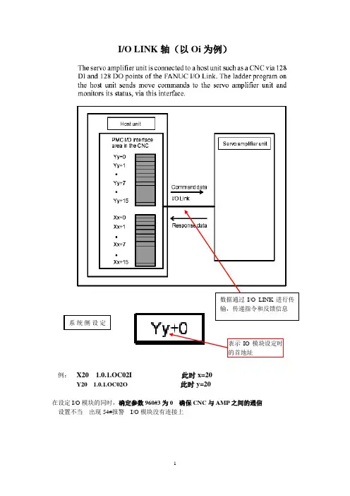
I/O LINK轴(以Oi为例)例:X20 1.0.1.OC02I 此时x=20Y20 1.0.1.OC02O 此时y=20在设定I/O模块的同时,确定参数960#3为0 确保CNC与AMP之间的通信设置不当出现54#报警I/O模块没有连接上硬件接线:B 放大器 JA35 EX IO 中接线当不使用外部减速挡块时,默认设置为0,采用无挡块回零方式参数设置:与普通的伺服电机具有相同的伺服设定急停互锁+超程 —超程初始化信号:信号相对简单,进行简单动作的控制这里的Y地址是CNC--→AMP 控制AMP执行指定的动作作用相当于平时所用的G地址信号这里的X地址是AMP--→CNC AMP反馈给CNC的信息目前AMP处在何种状态作用相当于平时所用的F地址信号操作:IO LINK控制方式由信号DRC的状态决定在操作时两种接口可以切换,但是由于两种接口的时序不同,改变时梯形图也要相应改变,通常上电时不要进行切换。
IO LINK运行方式大部分操作都是在JOG 和AUTO 两种方式下进行 它的方式可以独立于系统本身(HOST )方式的影响 通常与HOST 的工作方式串在一起 保持一致Y22 Y23Y26#7 #6 #5 #4 #3 #2 #1 #0|参数的保存:在参数画面的操作与常规的参数输入/输出相同1把参数以程序的形式,转到我们平时可以看到的程序画面2 把参数传到存储卡(960#1设1)操作如图所示:1.)选择要传出的参数画面2.按下软键[<OPRT>]按下菜单扩展键[ ]3.按下[READ]键但是它的输入/输出是AMP (B放大器) 与CNC MEMORY 之间。
当AMP-→CNC [ READ ]CNC-→AMP [ WRITE ]关于存储的程序号:在8760中设定所传出参数的程序号范围当8760中设定2000时传出的参数的程序号为2010 (即:2000+N x10 )注:N为放大器组号当该程序号已存在时设定3201#2 REP 是否将该程序覆盖。
第九节 IO Link轴控制

第九节I/O Link轴控制一、概述I/O Link轴的控制是通过系统的FANUC I/O Link对伺服电机进行控制的一种方法。
该控制方法的特点是通过PMC对该轴的动作进行控制,同时该轴不能与系统控制的其他伺服轴进行插补,另外该轴还需要占用系统I/O Link的输入输出点。
因此,该轴通常用来对系统的外围机构进行固定动作的控制,完成某种特定的动作和运动。
通常情况下,当系统提供的基本轴不够用时,为了增加CNC的控制轴数,但不需要该轴进行插补的情况下,利用FANUC系统提供的Power Mate CNC管理功能可以对I/O Link 轴进行控制,从而实现特定的运动。
常见的应用包括刀库控制、旋转工作台以及生产线上的点位控制等。
本节将就上述功能进行介绍,通过示例程序演示梯形图的编辑和功能的实现。
二、硬件连接1.接口I/O Link轴的驱动是通过βi系列放大器完成的。
该放大器通过I/O Link接口与系统相连,系统通过PMC梯形图对该接口的控制,完成对I/O Link轴的控制。
由于I/O Link轴的控制是通过FANUC I/O Link实现控制的,因此需要占用I/O Link的128个输入点和128个输出点。
图9.2.1 I/O Link轴放大器的连接示意图2.地址分配如上图2.1.1所示,当使用I/O Link作为系统与放大器之间的通讯时,需要设定通讯地址。
通过该通道完成通讯。
由于通过I/O Link对该轴的进行控制,因此该轴的地址分配符合系统对I/O地址分配的原则。
对于系统侧而言,进行I/O模块的地址分配时,需要分配一个16字节大小的模块。
例如:OC02I或者OC02O。
对于本书中关于I/O Link轴设定方面的地址表示方法,通常表示为:如果从Y50开始分配,则在Y50进行分配:1.0.1.OC02O ,此时y=50。
也就是说“y”表示开始的地址值。
在本节后面的叙述中,都将以X50与Y50作为起始地址进行叙述,但是在实际使用当中可以对其进行修改。
IO-Link 通信协议及其在工业物联网应用领域的用途

IO-Link 通信协议及其在工业物联网应用领域的用途本文将简要介绍IO-Link 通信协议及其在工业物联网应用领域的用途。
然后,本文将介绍Maxim Integrated MAX14827A 收发器,以示范如何针对各种工业检测和安全应用来部署经济高效的工业物联网边缘层节点。
IO-Link 概述IO-Link (IEC 61131-9) 是一种点对点串行通信协议,针对包含传感器、执行器和低功耗微处理器的智能边缘层节点进行了优化。
它的基本形式是三线连接,可以切换模拟和数字信号(8 位、12 位和16 位)。
它简明、智能、高效且可配置,并具有提供更多信息和控制的能力,因而得到了广泛的工业支持。
在典型的工业安装中,多个IO-Link 主站可操作执行器,并从传感器收集数据;它们还能够动态地重新配置传感器和执行器。
可编程逻辑控制器(PLC) 可能包含多个IO-Link 主站,每个主站连接到一个或多个器件。
PLC 本身是局域网(例如现场总线)上的节点。
诸如工业以太网之类的更高速网络,在PLC 集线器和更高的企业或云级别之间传输数据和命令。
IO-Link 标准引脚分配根据M5、M8、M12 的圆形外形尺寸,将数据链路和电源连接组合在单个连接器中:其中M12 最为常用。
传感器连接器有四个引脚,执行器有五个引脚:IO-Link 主站器件通常有五引脚插座。
该标准定义了两个端口类,即端口A 和端口B:引脚1、3 和4 在两个端口类中执行相同的功能。
在端口A 中,引脚2 和5 未指定具体功能,但制造商通常使用引脚2 作为附加数字通信通道。
在端口 B 中,引脚 2 和 5 为具有较大需求的器件提供额外电源。
IO-Link 规范具有后向兼容性,并能够适应旧有设备。
主站可以使用标准输入输出(SIO) 功能来操作这些器件,将C/Q 串行链路转化为分立式数字I/O 端口。
SIO 还支持IO-link 传感器与传统输入模块结合使用。
FANUC IO-LINK的设定

IO-LINK的设定一实习目的了解和掌握FANUC的IO单元和系统之间的硬件连线,掌握IO-LINK的软件设定,以及在调试或维修工作中进行信号强制的方法。
二 IO-LINK的相关概念对于对连接到IO单元的信号地址的定义,系统需要先确定每个IO单元在串行回路中的物理位置。
然后确定每个IO单元Xm/Yn的m、n单元的起始地址(当每个IO单元的起始地址定义好后,对应于IO单元上每个物理输入点就都具备了确定的地址)。
物理地址的表示含义:组、座、槽组:系统的JDIA到IO单元的JD1B、IO单元的JD1A到下一单元的JD1B,形成串行通讯。
每个从属的IO单元就一个组,组的顺序以离系统的连线顺序而依次定义为0、1···· 、n(n=15)座:对于特殊模块IO-UNIT来说,在一个组中可以连接有扩展单元。
因此,对于基本模块和扩展模块可以分别定义成0座、1座,对于其他的通用IO模块来说都是默认的0座。
槽:对于特殊模块IO-UNIT来说,在每个座上都有相应的模块插槽,定义时要分别以安装的插槽顺序1、2···、10来定义每个插槽的物理位置。
如图确定了IO 单元的物理连接顺序后,其相应的组号就确定了,然后可以通过系统的IO-LINK 的设定画面来定义每个IO 单元所对应的起始地址m/n 。
三:具体实习操作:1) 查看实际系统和外部IO 单元的连接顺序,确定每个IO 单元的组号。
2) 检查系统画面所诊断出的IO 单元的数量和实际的单元的数量是否一致。
操作:[SYSTEM ]→[PMC]→[PMCDGN]→[IOCHCK]→[IOLNK]3) 确定每个每个IO 单元的起始地址后,进入IO-LINK 的设定画面进行设定。
确定数量0座1槽2槽第0组第1组第2组操作:[SYSTEM]→[PMC]→[PMCPRM]→[SETTING]设定此参数为1,然后进入IO-LINK设定画面。
西门子 通信模块 IO-Link Master CM 4xIO-Link (6ES7137-6BD0
SIMATICET 200SP通信模块IO-Link Master CM4xIO-Link (6ES7137-6BD00-0BA0)设备手册法律资讯警告提示系统为了您的人身安全以及避免财产损失,必须注意本手册中的提示。
人身安全的提示用一个警告三角表示,仅与财产损失有关的提示不带警告三角。
警告提示根据危险等级由高到低如下表示。
危险表示如果不采取相应的小心措施,将会导致死亡或者严重的人身伤害。
警告表示如果不采取相应的小心措施,可能导致死亡或者严重的人身伤害。
小心表示如果不采取相应的小心措施,可能导致轻微的人身伤害。
注意表示如果不采取相应的小心措施,可能导致财产损失。
当出现多个危险等级的情况下,每次总是使用最高等级的警告提示。
如果在某个警告提示中带有警告可能导致人身伤害的警告三角,则可能在该警告提示中另外还附带有可能导致财产损失的警告。
合格的专业人员本文件所属的产品/系统只允许由符合各项工作要求的合格人员进行操作。
其操作必须遵照各自附带的文件说明,特别是其中的安全及警告提示。
由于具备相关培训及经验,合格人员可以察觉本产品/系统的风险,并避免可能的危险。
按规定使用 Siemens 产品请注意下列说明:警告Siemens 产品只允许用于目录和相关技术文件中规定的使用情况。
如果要使用其他公司的产品和组件,必须得到 Siemens 推荐和允许。
正确的运输、储存、组装、装配、安装、调试、操作和维护是产品安全、正常运行的前提。
必须保证允许的环境条件。
必须注意相关文件中的提示。
商标所有带有标记符号 ® 的都是 Siemens AG 的注册商标。
本印刷品中的其他符号可能是一些其他商标。
若第三方出于自身目的使用这些商标,将侵害其所有者的权利。
责任免除我们已对印刷品中所述内容与硬件和软件的一致性作过检查。
然而不排除存在偏差的可能性,因此我们不保证印刷品中所述内容与硬件和软件完全一致。
印刷品中的数据都按规定经过检测,必要的修正值包含在下一版本中。
io link 芯片 通讯原理
io link 芯片通讯原理io link芯片是一种用于工业自动化领域的通信接口技术,它可以实现传感器和执行器与上位机之间的数据交换和通信。
io link芯片的通讯原理是基于串行通信协议来实现的。
io link芯片的通讯原理主要包括物理层和数据链路层两个部分。
在物理层,io link芯片使用三线制的串行通信方式进行数据传输,包括一个通信线、一个电源线和一个接地线。
通信线用于传输数据和通信命令,电源线用于为传感器或执行器供电。
在数据链路层,io link芯片采用了一种双向通信的协议,可以实现从上位机向传感器或执行器发送数据,同时也能够接收传感器或执行器返回的数据。
在io link芯片的通讯过程中,首先需要建立通信连接。
上位机通过发送一个初始化命令来激活io link芯片,并指定要通信的传感器或执行器的地址。
接下来,上位机可以向传感器或执行器发送数据和命令,并等待其返回响应。
传感器或执行器接收到数据后,会进行处理并返回相应的结果给上位机。
整个通讯过程是通过一系列的数据帧来完成的,每个数据帧包括起始位、数据位、校验位等。
io link芯片的通讯原理具有以下特点:1. 高可靠性:io link芯片采用了差分信号传输和CRC校验等技术,可以有效地提高通信的可靠性和抗干扰能力。
2. 高灵活性:io link芯片支持多种不同的传感器和执行器,可以适应不同的应用场景和需求。
同时,io link芯片还支持参数的动态配置和调整,可以实现对传感器或执行器的灵活控制。
3. 易于集成:io link芯片具有简单的硬件接口和易于使用的软件开发工具,可以方便地与上位机进行集成和通信。
此外,io link芯片还支持远程诊断和故障排除,可以提高系统的可维护性和可靠性。
io link芯片是一种能够实现传感器和执行器与上位机之间数据交换和通信的技术。
它的通讯原理基于串行通信协议,具有高可靠性、高灵活性和易于集成等特点。
通过使用io link芯片,可以实现工业自动化系统的智能化和网络化,提高生产效率和质量。
Festo IO-Link参数描述(版本1.10)说明书
Application NoteIO-Link parameter descriptionA brief explanation of the contents - identification- parameter and commands- block parameterization- teach-In- process data- diagnosis SCDN-.......... signalconverter100147Title .......................................................................................................................... IO-Link parameter description Version ............................................................................................................................................................. 1.10 Document no. . (100147)Original .................................................................................................................................................................en Author ............................................................................................................................................................. F estoLast saved ............................................................................................................................................ 08.05.2017Copyright NoticeThis documentation is the intellectual property of Festo AG & Co. KG, which also has the exclusive copyright. Any modification of the content, duplication or reprinting of this documentation as well as distribution to third par-ties can only be made with the express consent of Festo AG & Co. KG.Festo AG & Co KG reserves the right to make modifications to this document in whole or in part. All brand and product names are trademarks or registered trademarks of their respective owners.Legal NoticeHardware, software, operating systems and drivers may only be used for the applications described and only in conjunction with components recommended by Festo AG & Co. KG.Festo AG & Co. KG does not accept any liability for damages arising from the use of any incorrect or incomplete information contained in this documentation or any information missing therefrom.Defects resulting from the improper handling of devices and modules are excluded from the warranty.The data and information specified in this document should not be used for the implementation of safety func-tions relating to the protection of personnel and machinery.No liability is accepted for claims for damages arising from a failure or functional defect. In other respects, the regulations with regard to liability from the terms and conditions of delivery, payment and use of software of Festo AG & Co. KG, which can be found at and can be supplied on request, shall apply.All data contained in this document do not represent guaranteed specifications, particularly with regard to func-tionality, condition or quality, in the legal sense.The information in this document serves only as basic information for the implementation of a specific, hypo-thetical application and is in no way intended as a substitute for the operating instructions of the respective manufacturers and the design and testing of the respective application by the user.The operating instructions for Festo products can be found at .Users of this document (application note) must verify that all functions described here also work correctly in the application. By reading this document and adhering to the specifications contained therein, users are also solely responsible for their own application.(Festo AG & CO. KG, D-73726 Esslingen, 2017)Internet: E-Mail: *******************************Table of contents1Components/Software used (4)2IO-Link operating mode (5)3Technical data (6)3.1General specification (6)3.2Communication features (6)3.3On demand data (7)3.3.1Identification parameters (7)3.3.2Standard IO-Link parameters and commands (8)3.3.3Smart Sensor Profile parameters (9)3.3.4IO-Link Teach-In (11)3.3.5Device specific parameters (14)3.3.6Block parameterization (18)3.4Process Data IN (20)3.5Conversion factors for the parameters ProcessDataVariable, ProcessDataVariable Min,ProcessDataVariable Max, and Setpoints SP1, SP2 (21)3.6Conversion factors for the Hysteresis, Switchpoint d.SP and Max Signal-Delta (s.obS) (21)3.7Diagnosis (22)3.8I-Port (23)Components/Software used1Components/Software usedTable 1.1: Components/Software usedNoteYou can find detailed specifications on the product, the instruction manual and the declaration ofconformity at:→ Detailed information on the IO-Link specification V1.1 und the Smart Sensor Profile at:→ The device description file IODD at:→ /spIO-Link operating mode 2IO-Link operating modeIn the IO-Link operating mode, programmed switching signals and the continuously measured process values (digi-tally coded analogue values) are transferred.– Data transmission is serially and digitally coded in the IO-Link protocol– Usage of unshielded standard cables up to 20 m length is possible– Process data: 14 bit for each measurement value (InA and InB) and 2 bit for the binary channels– Parameters and functions in accordance with Smart Sensor Profile– There are two binary channels available, which can be individually programmed as threshold value comparator, window comparator or Auto difference monitoring– The threshold and window comparator can be set for quantity detection, object (presence) detection or position detection– Each binary channel is adjustable as normally closed (NC) or normally open (NO)– The continuously measured values are always transferred parallel and independent of the binary channels– Support of optional functions Block Parameterisation and Data Storage– Display IO-Link operation: “OutA” segment switches off every 2 seconds for the period of 0,1 seconds– The keys are locked during a parameter access, afterwards the device returns automatically into the RUN mode– Device description file IODD for all variantsTechnical data3Technical data3.1General specificationTable 3.1: General IO-Link specification3.2Communication features-Preoperate: Frame type 1_V, OD-capability 8 bytes -Operate: Frame type 2_V, OD-capability 2 bytes-SIO-Mode: supported-ISDU: supported-Data storage: supported-Block parameterization: supportedTechnical data3.3On demand dataThe detailed description of these parameters can be found in the IO-Link Interface and System specification, in the IODD and in the IO-Link Smart Sensor Profile. The default values and the respective valid ranges of these parame-ters are listed in the IODD xml file.3.3.1Identification parametersVendor ID 333 d / 01 4D hDevice ID see the following tableTable 3.2: Device IDs1) Authorisation group: U = user, M = maintenance, S = specialist; access: R = read, R/W = read and write, – = no access2) Value defined by userTable 3.3: Identification parametersTechnical data3.3.2Standard IO-Link parameters and commands1) Authorisation group: U = user, M = maintenance, S = specialist; access: R = read, R/W = read and write, – = no access2) Bit 0: lock Parameter Write Access; Bit1: lock data storage (no impact); Bit2: lock local parameterization (EDIT- and TEACH-Mode); Bit3: lock local user interface (not used)Table 3.4: Standard IO-Link parameters1) Authorisation group: U = user, M = maintenance, S = specialist; access: R = read, R/W = read and write, – = no accessTable 3.5: Standard IO-Link commandsTechnical data 3.3.3Smart Sensor Profile parametersTechnical data1) Authorisation group: U = user, M = maintenance, S = specialist; access: R = read, R/W = read and write, – = no access Table 3.6: Smart Sensor Profile parameters3.3.4IO-Link Teach-InThe remote Teach-In procedure via IO-Link is the same as the manual one. Instead of key pressing the teaching points will be taught by the corresponding commands from IO-Link Smart Sensor Profile. The chronological order of determining teaching points does not matter either.All switching functions require two applied Teach-In values.In case of an exceeded signal event every teach command causes ISDU error “function temporarily unavailable”0x8036 and the Teach-In procedure is cancelled. If the Teach-In mode was not yet started, then the device will re-main in the run mode.An overview of the Teach-In commands Table 3.5:The device starts the Teach-In procedure as soon as a successful Teach-In command is received. It sets the corre-sponding teach point, the teach state, the status “successfully taught“ and waits for the second command. The keys A, B and EDIT are locked and the display flashes alternately “t-IN / IOL “until either the Teach-In procedure is successfully completed or aborted. The display shows the currently measured process value.In contrast to the manual Teach-In procedure a teach point can be repeatedly set with the commands 0x41, 0x42,0x43 and 0x44. This procedure is regardless of the chronological order of applying the teach signal TP1 or TP2.In case an invalid command, respective to the current switching / Teach-In mode, is sent, the device will signal the ISDU error “function temporarily unavailable” 0x8036.If the first teach command comes once more before the second one, then the currently measured process value will be used again for the first teach point. After sending of second teach command all successfully calculated switching points will be immediately taken over and the remote Teach-In procedure will end. The Teach Apply command 0x40 is not used during Teach-In process.All Teach-In commands are in format UInterger8. They should be sent with the index 0x0002 (system command) sub-index 0.noteThere is also a specific Teach-In command 0x4B, which is used in IODD to simulate key pressing in IODDdevice tool. This command reflects the logic of the manual Teach-In and operates analogous to the localTeach-In via display and keys. Additionally this command can ease the use of the Teach-In functionsprovided by IO-Link for customer applications.∙In mode threshold value comparator the first sending of this command equates to the “SP1 two value teach TP1” command 0x43 and the second sending equates to the “SP1 two value teachTP2” command 0x44∙In mode window comparator and Auto Difference Monitoring the first sending equates to the “SP1 single value teach” command 0x41 and the second equates to the “SP2 single valueteach” commands 0x42.For more information see IO-Link Smart Sensor Profile.Table 3.7: Overview of switching functions1) For Auto Difference Monitoring: Teach-In is only available for the limits of the work range (SP.Lo and SP.Hi).2) By changing the switching function an inconsistent set of parameters for switchpoint mode, SP1, SP2, HY could occur which prevents the switching function to be changed. An appropriate error message is shown. In this case it is recommended to restore the factory settings. With the factory settings a free choice of a switching function is always possible.Table 3.8: Teach-In commands3.3.5Device specific parameters1) Authorisation group: U = user, M = maintenance, S = specialist; access: R = read, R/W = read and write, – = no access Table 3.9: Device specific parameters3.3.6Block parameterizationWith this feature the sending of invalid parameters to a device can be prevented. Individually sent parameter values are possibly not compatible with the parameter values already stored in the device. The parameters trans-mitted as a block will be simultaneously accepted and activated.For SCDN there are six blocks of parameters:Block parameterization for BDC1 (OutA)Table 3.10: Block of OutA coherent parametersBlock parameterization for BDC2 (OutB)Table 3.11: Block of OutB coherent parametersBlock parameterization for scaling the input signal InATable 3.12: Block of InA signal coherent parametersBlock parameterization for visualisation of input signal InA on the displayTable 3.13: Block of InA display coherent parametersBlock parameterization for scaling the input signal InBTable 3.14: Block of InB signal coherent parametersBlock parameterization for visualisation of input signal InB on the displayTable 3.15: Block of InB display coherent parameters3.4Process Data INTable 3.16: Process data mappingTechnical data 3.5Conversion factors for the parameters ProcessDataVariable, ProcessDataVariableMin, ProcessDataVariable Max, and Setpoints SP1, SP2The conversion factors, necessary for the correct representation of the measurement values and the switching points in different physical units in the control unit, are:There are 5 predefined measurement ranges. For conversion between process values and measurement values the following conversions factors can be used.In case of a customer-specific setting of the measured value indicator the conversion between process value and measurement value is done by calculation of Offset and Gradient of the linear equation.MV = Gradient x Process value + OffsetMV.Lo = Gradient x 0 + Offset => Offset = MV.LoMV.Hi = Gradient x 16383 + Offset => Gradient = (MV.Hi – MV.Lo) / 163833.6Conversion factors for the Hysteresis, Switchpoint d.SP and Max Signal-Delta (s.obS) For predefined measurement ranges see table 3.17For customer–specific setting of the measure value indicator the conversion between process value and measure-ment value is done by calculation of Offset and Gradient of the linear equation.Offset = 0Gradient = (MV.Hi – MV.Lo) / 16383Technical data3.7DiagnosisTable 3.19: Supported errors and warningsTechnical data 3.8I-PortI-Port is an internal technology for automatically identification of Festo devices on I-Port compatible master.Table 3.20: Supported I-Port IndexesThe parameters for the Switch output OutA can be configured in case of threshold comparator (Single point mode ) and window-comparator (W indow mode).Table 3.21: Mapping of Smart Sensor Profile Indexes on I-Port parameter 0x43。
IO-Link技术规范简介
IO-Link技术规范简介
菲尼克斯电气中国公司 自动化产品经理:孙林宝
1 目录
1 目录 ........................................................................................................................................... 2 2 IO-Link 系统概述 ....................................................................................................................... 3
总线中。这就是现场总线中的IO-Link映射。如果IO-Link主站通过专用背板总线直接连接PLC(见 图1),IO-Link数据映射到该总线,然后传输到PLC,或从PLC传到IO-Link主站,再由主站继续传 输到IO-Link设备。IO-Link映射适用于PROFIBUS、Profinet、INTERBUS、AS-i和EtherCAT。
3.4 传输质量、重试、QoS
IO-Link是功能强大的数据传输系统,其运行电压为24V。某帧传输失败时,主站将重复发送两 次请求。只有第二次数据发送失败时,主站才会检测为通信中止,并向高层控制系统发送报告。主 站通过报文重复次数(重试次数)评估传输质量(QoS即服务质量)。
3.5 传输速率和同步率