造纸机驱动 的电路控制Electronic Line-Shafting Control
造纸机的直流电机速度控制系统设计
辽宁工业大学电气控制与PLC技术课程设计(论文)题目:造纸机的直流电机速度控制系统设计院(系)专业班级:学号:学生姓名:指导教师:(签字)起止时间:课程设计(论文)任务及评语院(系):电气工程学院教研室:自动化注:成绩:平时20% 论文质量60% 答辩20% 以百分制计算摘要造纸是一个连续生产的过程,因此生产线的连续和有序控制成为了制约成品纸质量和产量的瓶颈。
直流调速适用于大中纸机和滑差电机适用于中小纸机天下的造纸领域,并已近取得良好的市场效果。
直流调速系统在纸机的发展史上占有重要的地位。
本文首先详细的介绍了直流调速系统的基本原理,分析了调速系统的基本组成以及基本调速方法;然后系统的论述了现代PLC控制技术,介绍了PLC控制系统的基本设计方法;并采用串电阻方法对系统的主电路进行了设计,并介绍了主电路的每一个组成部分。
包括低压断路器、熔断器、接触器、三相桥式整流电路以及直流电机和主电路的保护元件。
结合现代PLC控制技术对调速系统运行进行控制,对电动机、晶闸管等元件主要参数进行详细的计算;最后利用protel电路图绘制软件对相关电路图进行绘制并用STEP 7软件进行程序编写并进行仿真及调试,实现控制要求。
关键词:直流调速;串电阻调速;S7-200 PLC目录绪论钋鸢嗨 (3)第2章控制系统的设计钋鸢嗨 (5)2.1概述钋鸢嗨 (5)2.2调速方案设计钋鸢嗨 (5)2.3总体实现方案钋鸢嗨 (6)第3章系统硬件设计钋鸢嗨 (7)3.1PLC的选择钋鸢嗨 (7)3.1.1PLC的基本结构和工作原理钋鸢嗨 (7)3.1.2PLC的组成和分类钋鸢嗨 (8)3.1.3PLC硬件选择钋鸢嗨 (8)3.2主电路钋鸢嗨 (9)3.2.1低压断路器钋鸢嗨 (10)3.2.2熔断器钋鸢嗨 (10)3.2.3接触器钋鸢嗨 (11)3.2.4整流电路钋鸢嗨 (12)3.2.5电路元件参数计算钋鸢嗨 (12)3.2.6主电路图钋鸢嗨 (13)3.3PLC的外部接线钋鸢嗨 (13)3.4系统中PLC的I/O分配表设计钋鸢嗨 (14)第4章系统软件设计钋鸢嗨 (16)4.1流程图钋鸢嗨 (16)4.2软件的选用钋鸢嗨 (17)第5章系统测试与分析钋鸢嗨 (19)第6章课程设计总结钋鸢嗨 (21)参考文献钋鸢嗨 (22)第1章绪论造纸术是中国四大发明之一,有着悠久的历史。
造纸机电气传动全数字自动化控制系统研究
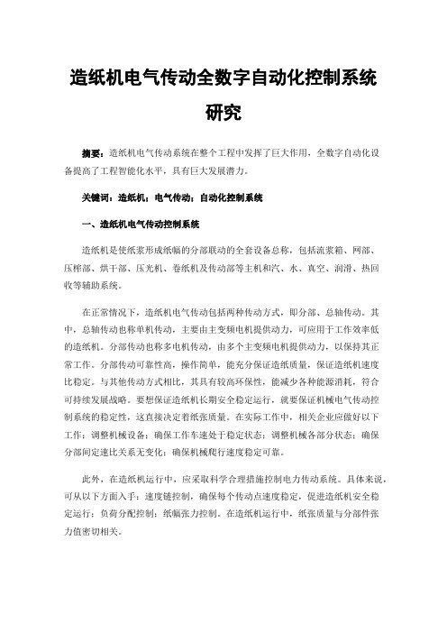
造纸机电气传动全数字自动化控制系统研究摘要:造纸机电气传动系统在整个工程中发挥了巨大作用,全数字自动化设备提高了工程智能化水平,具有巨大发展潜力。
关键词:造纸机;电气传动;自动化控制系统一、造纸机电气传动控制系统造纸机是使纸浆形成纸幅的分部联动的全套设备总称,包括流浆箱、网部、压榨部、烘干部、压光机、卷纸机及传动部等主机和汽、水、真空、润滑、热回收等辅助系统。
在正常情况下,造纸机电气传动包括两种传动方式,即分部、总轴传动。
其中,总轴传动也称单机传动,主要由主变频电机提供动力,可应用于工作效率低的造纸机。
分部传动也称多电机传动,由多个主变频电机提供动力,以保持其正常工作。
分部传动可靠性高,操作简单,能充分保证造纸质量,保证造纸机速度比稳定。
与其他传动方式相比,其具有较高环保性,能减少各种能源消耗,符合可持续发展战略。
要想保证造纸机长期安全稳定运行,就要保证机械电气传动控制系统的稳定性,这直接决定着纸张质量。
在实际工作中,相关企业应做好以下工作:调整机械设备;确保工作车速处于稳定状态;调整机械各部分状态;确保分部间定速比关系无变化;确保机械爬行速度稳定可靠。
此外,在造纸机运行中,应采取科学合理措施控制电力传动系统。
具体来说,可从以下方面入手:速度链控制,确保每个传动点速度稳定,促进造纸机安全稳定运行;负荷分配控制;纸幅张力控制。
在造纸机运行中,纸张质量与分部件张力值密切相关。
目前纸机传动方式发生了重大变化,造纸机正逐步引入一些先进技术及工作理念,以更好地适应时代发展,满足人们对造纸机的要求,促进其可持续发展。
调查结果表明,造纸机最常用传动控制系统是三级控制模式,以数字、模拟控制为控制方式。
造纸机模拟控制系统构造简单,操作流程简单明了,对工作人员技术要求不高,能降低操作失误概率,延长造纸机使用寿命。
造纸机在模拟控制模式下具有较高工作效率和可靠性,并能长时间工作。
数字控制系统是社会快速发展的产物,主要用于一些高速纸机,通过科学合理应用数字通信技术,使纸机逐步向全数字化发展,充分保证设备良好运转。
造纸机电气传动的现状和发展趋势的探讨

造纸机电气传动的现状和发展趋势的探讨【摘要】造纸机电气传动作为造纸行业中不可或缺的重要组成部分,其在提高生产效率、节能减排、提升产品质量等方面发挥着关键作用。
本文从造纸机电气传动的现状和发展趋势出发,对其技术应用和优势进行深入分析。
电气传动技术在造纸机中的应用现状及其在制浆、造纸等环节中的优势和局限性也得到探讨。
特别是电气传动技术的不断发展对整个造纸行业的影响备受关注。
展望电气传动在造纸机中的应用前景,总结其优势与挑战,展望未来发展方向,旨在为造纸机电气传动领域的研究和应用提供一定的指导和参考价值。
【关键词】造纸机,电气传动,现状,发展趋势,应用,优势,局限性,影响,前景,展望,技术,未来发展方向1. 引言1.1 介绍造纸机电气传动的重要性造纸机电气传动是造纸生产过程中至关重要的一环。
它通过电气装置实现对造纸机械设备的精准控制,提高了生产效率,降低了能耗,保障了生产质量。
传统的机械传动方式存在着传动损耗大、调速范围窄、维护成本高等问题,而电气传动技术的使用可以有效地解决这些问题,提升造纸生产的整体水平。
在如今高度信息化、智能化的时代背景下,电气传动技术已经成为造纸机械设备的主流,引领着制造业的发展方向。
通过对造纸机的电气传动进行优化,不仅可以提高设备的可靠性和稳定性,还可以实现生产线的智能化管理,实现远程监控和故障诊断,进一步降低了生产成本,提升了企业的竞争力。
深入探讨造纸机电气传动的现状和未来发展趋势,对于造纸行业的转型升级和提升竞争力具有重要意义。
本文将就此展开研究与讨论,探索电气传动技术在造纸机中的应用前景,为行业发展提供参考与借鉴。
1.2 概述本文内容本文将探讨造纸机电气传动的现状和发展趋势,旨在分析电气传动技术在造纸行业中的重要性和应用情况。
我们将对造纸机电气传动的现状进行详细分析,包括其在造纸生产中的具体应用情况和存在的问题。
接着,我们将探讨造纸机电气传动技术的发展趋势,包括当前的发展状况和未来的发展方向。
关于造纸机电气传动控制系统的应用与质量控制

关于造纸机电气传动控制系统的应用与质量控制摘要:随着全球造纸业及其相关行业的发展,人们不仅对纸页的依赖性越来越强,还对纸页的质量要求越来越严格。
尤其是近几年,造纸业已经成为国际自动化程度非常高的行业之一,一个国家各类纸张的消费水平,从某种程度上标志了这个国家的文明程度。
本文主要探讨的就是关于造纸机电气传动控制系统的应用与质量控制。
关键词:造纸机;电气传动;控制系统;质量控制引言:国外造纸业对纸机系统的研究已经取得了丰硕的成果,尤其是大大提升了纸机电气传动控制系统的整体自动化水平。
1.国内纸机传动现状目前,国内的造纸业发展迅速,进入二十一世纪我国单台纸机能力的记录频频被刷新,我国已成为了世界上大型新纸机最多的国家。
大型纸机如海南金海浆纸的PM2,纸幅宽度达到12米,车速为2000米/分钟,产量约为120万吨/年,总传动容量为40157kW,189个传动点。
在这种大容量、高车速,高精度的纸机传动系统产品供应中,国际电气的巨头西门子、ABB占据着主要供应商的位置,其他国际品牌像GE、东芝、三菱等则由于水土不服,一直鲜有供货的案例,而杭州华章、上海华欣、上海造纸电控所等国内电气企业则主要还是占据着中小纸机传动的市场。
未来纸机的电气传动的发展,取决于电力电子技术的进一步发展。
根据当前的发展趋势,我们预计未来造纸机速度将进一步加快,纸机负载容量将进一步增加,纸机电气传动需要进一步发展在以下方面:(1)电力的传输能力,目前需要更高的供电电压来满足供电需求,电压越高,所有的电损就越小;(2)调速的精度提出了更高的要求,随着纸机速度加快,速度控制的小错误可能引起断纸,因此,对高精度调速的要求将会越来越多;(3)节能减排的要求,将采用更低损耗的技术,如:直接转矩控制、能量回馈技术;(4)由于大量使用交流变频驱动,导致电网谐波产生,如何更加经济的抑制谐波,是未来电气传动发展面临的问题。
2.造纸机工作原理造纸机是一种由多个设备分部联动的机器,从第一个初步制造成品纸的机器在1803年到目前为止,造纸机总体机械结构逐渐完美,有固定的造纸行业技术规范,即整个制作过程由湿部和干部组成:其中湿部包括:纸浆流送系统、流浆箱、成形网和压榨部;干部包括:前烘,施胶,后烘,涂料,压光和卷纸。
造纸机电气传动控制系统的设计与实现

造纸机电气传动控制系统的设计与实现造纸机电气传动控制系统的设计与实现摘要:随着现代纸张工业的发展,造纸生产线的自动化程度越来越高。
为了提高生产效率和质量,电气传动控制系统在造纸机中起着至关重要的作用。
本文主要介绍了造纸机电气传动控制系统的设计和实现,包括系统结构、硬件设计和软件开发等方面的内容。
一、引言纸张工业作为国民经济的支柱产业之一,在我国经济发展中占有重要地位。
随着纸张需求的不断增长,提高造纸生产线的自动化水平成为迫切的需求。
电气传动控制系统在提高生产效率和质量方面发挥着重要作用。
本文旨在设计和实现一种高效、稳定的电气传动控制系统,以满足造纸机的自动化需求。
二、系统结构设计电气传动控制系统主要由电机、传感器、控制器和执行器组成。
电机作为主要动力装置,通过传感器采集参数,并由控制器对电机进行控制,最后通过执行器实现纸张的运动。
1. 电机选择造纸机电气传动控制系统中常采用交流变频电机作为驱动源。
其具有调速范围广、转矩稳定等优点,适用于不同工况的需求。
2. 传感器应用在电气传动控制系统中,传感器主要用于采集各种参数,如纸张的长度、宽度、张力等。
根据传感器输出信号的特点,可以对纸张的运动状态进行实时监测和控制。
3. 控制器设计控制器是电气传动控制系统的核心部分,主要负责对电机进行控制和调节。
可以采用PLC(可编程逻辑控制器)作为控制器,通过编写程序实现对电机的启停、正反转等功能。
4. 执行器选择在电气传动控制系统中,执行器主要负责将控制信号转换为运动,并实现纸张的进给、送纸等功能。
可选用液压缸、气动缸等执行器,根据纸张的要求和系统的可靠性进行选择。
三、硬件设计1. 电气传动装置的安装根据造纸生产线的实际情况,将电气传动装置合理地安装在机器的关键位置,以便实现对纸张的精准控制。
2. 传感器布置传感器布置应与纸张运动轨迹相匹配。
通过合理布置,可以实现对纸张宽度、张力等参数的实时监测。
3. 控制器接线控制器与电机之间的接线应准确、牢固。
造纸机传动系统电气自动化及变频调速控制技术

造纸机传动系统电气自动化及变频调速控制技术摘要:电气自动化控制技术不断进步与发展,被应用到了人们生活的各个方面,给生活与生产带来了诸多方便,但电气自动化控制设备一般耗费的资源较多。
针对这一高能耗问题,必须要借助于变频调速技术来实现共赢,同时要提升整体效率与品质。
本章将对电气自动化控制系统中的变频调压方法展开细致探讨,并给出一些意见,期望能够为有关人员带来借鉴意见。
概述变频器科技成为一项新型的电源节约科技,现已被运用到各个行业,也可以避免某些传统工频技术所存在的不足。
关键词:电气自动化;变频调速;控制技术近年来,电气行业获得了长足的发展和进步,许多电气设备和系统也在不断地优化和革新。
在工业领域,电气自动化控制系统能够有效提高工作效率。
电气自动化控制系统不但能够大大提高工厂的制造品质和工作效率,还能够减少工厂的产品消耗,符合工厂的基本制造条件。
反之,则会给企业带来巨大的损失。
所以,为使电气自动化控制系统真正地发挥功能作用,有关的科技人员应当加强对变频调速关键技术的研发和利用。
1.造纸机械设备的组成和原理造纸机械包括原料设备,制浆设备,造纸机等。
该部是造纸机的一部分,分网部,压榨部,预压榨部,后压榨部,后压部,压光部和卷取部。
按纸张成型的先后顺序。
造纸机械设备可分为主纸生产用和副纸加工用两大类。
主纸生产用造纸机械设备主要有:打浆、漂白、抄造、施胶、脱水及后处理等。
副纸加工用造纸机械设备主要包括压光和收卷。
其特征在于:流浆箱产出的纸浆经过脱浆形成于流浆箱部内,经过压榨部内的挤压使得纸层平整,经过预压和干燥,再经过压榨和涂胶处理,然后经过压光机进行压光处理最终收卷形成母纸卷。
2.造纸机电气系统需求分析2.1速度要求造纸机从浆向纸的转化要经过压浆施胶,压榨,压燥,压光和卷绕等几个多段的步骤,这是一个单元速度协调系统。
其品质控制效果的优劣,影响产品服务质量与生产。
因此,要保证造纸过程稳定地进行并取得良好的效益,每个段与段之间均存在着严格的快慢度关系和例数关系,否则将导致断纸或过松,对纸张各项物理指标产生影响,对纸张定量控制不稳、影响产品质量。
造纸机传动工艺要求和变频器选择与参数设置
造纸机传动工艺要求和变频器选择与参数设置造纸机有多种形式,不同的生产品种要求有不同的形式,对于分部传动控制系统可以有多种选择。
本章重点讨论纸机各个部位对传动的不同工艺要求,在此基础上选择不同的控制方法,用于选择对应的传动系统。
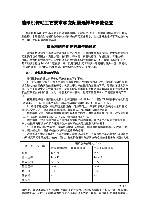
造纸机的传动要求和传动形式造纸机传动装置的形式应按造纸机的生产品种、产量和质量等来选择。
大型高速造纸机的主要传动点分别为:真空伏辊、驱网辊、导网辊、真空吸移辊、毛毯压榨、传递压榨、烘缸、压光机和卷纸机等。
由于造纸机的压榨部和烘干部的组数、机内配置情况等的不同,其传动点总数达14~20个或更多,中,低速造纸机的传动点一般的相对较少一些。
有的纸机机内配置有涂布机、软压光机, 其传动点总数多达45个以上。
3.1.1造纸机传动的要求任何配制的造纸机对于传动系统都有如下的要求:1、工作速度的调节:为了使造纸机有较大的产品和原料的适应性,造纸机传动应能保证在较大的范围内均匀的调节速度。
这是由于生产的纸种和定量的不同,需要改变纸机的车速。
又由于具体生产条件如打浆度、浆料配比与种类等的变化会影响浆料在网上的脱水速度和烘缸单位面积的产量。
因此,即使生产同一种纸,也常常需在10%~15%的范围内调节车速。
在专用造纸机(例如新闻纸机)上调速范围I=1:或I=1:2。
在生产印刷及书写用纸的造纸机上,I=1:5。
而在生产工业用纸及高级纸的造纸机上,I=1:8及I=1:10。
2、维持车速稳定:纸机的速度往往由于电源的电压、频率以及纸机负荷等因素的变化而发生变动。
为了稳定纸的定量和减少纸幅断头,要求纸机采用稳速装置。
稳速精度决定于纸的定量的偏差和纸幅不发生断头。
速度偏差最大允许值,对包装纸为±2~3%,对中等质量的纸为±1~2%,对印刷纸为±~1%。
顺便指出,要很准确的调节上网的浆料量是比较困难的,因此在生产规定定量的纸种时,往往用稍稍调节纸机车速的方法来控制纸的实际定量使之符合要求。
造纸废水处理电气控制原理图纸
- 1、下载文档前请自行甄别文档内容的完整性,平台不提供额外的编辑、内容补充、找答案等附加服务。
- 2、"仅部分预览"的文档,不可在线预览部分如存在完整性等问题,可反馈申请退款(可完整预览的文档不适用该条件!)。
- 3、如文档侵犯您的权益,请联系客服反馈,我们会尽快为您处理(人工客服工作时间:9:00-18:30)。
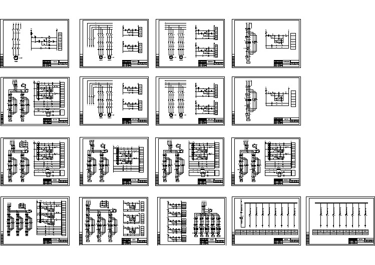
Electronic Line-Shafting Control for Paper Machine DrivesM.Aníbal Valenzuela and Robert D.Lorenz,Fellow,IEEEAbstract—The current synchronized motion control methods used in paper machine drives are not designed to possess the inter-shaft stiffness properties which were responsible for the coordinating force inherent in classical,mechanically coupled paper machines.Consequently,these controllers cannot easily maintain coordination for all operating conditions.This paper presents the application of an“electronic line-shafting”control technique which serves to replicate and even improve on the historical,mechanical line-shafted properties.This technique was tested on a four-shaft experimental setup to evaluate such control during periods of drive-limited torque as well as sectional drive load disturbances.The experimental results demonstrate that the “electronic line-shafting”technique significantly improves the coordination,robustness,and overall stability of paper machine drives subjected to realistic physical limitations.Index Terms—Multi-axis synchronization,paper machine con-trol,relative stiffness control,virtual line-shaft control.I.I NTRODUCTIONL ONG AGO,early paper machine drives were constructed with mechanical interconnection components that pro-duced motion with respect to a common line-shaft input.The mechanical power was produced by a single motor driving a line shaft to which all of the in-shafts were attached.Fig.1shows a simplified arrangement of a line-shaft drive. It consists of a speed-controlled motor driving a long shaft all the way along the different mechanical sections.Each section is coupled to the line shaft through a gear box,conical pulleys, and the section connecting shaft.Conical pulleys allow draws to be set in the different mechanical sections.Assuming no belt slip in the conical pulleys,this mechanical arrangement assures that all the system shafts will remain rigidly locked to each other through the common line shaft,even in the presence of distur-bances on individual sections.The only steady-state relative mo-tion is due to torsional windup of shafts transmitting the driving torque.Paper PID00–27,presented at the2000IEEE Pulp and Paper Industry Con-ference,Atlanta,GA,June19–23,and approved for publication in the IEEE T RANSACTIONS ON I NDUSTRY A PPLICATIONS by the Pulp and Paper Industry Committee of the IEEE Industry Applications Society.Manuscript submitted for review June23,2000and released for publication October19,2000.This work was supported by the Consolidated Papers Foundation.M.A.Valenzuela is with the Department of Electrical Engineering,Univer-sity of Concepción,Concepción,Chile(e-mail:avalenz@die.udec.cl).R.D.Lorenz is with ISEA-The Power Electronics and Drives Institute,Tech-nical university of Rhein-Westfalen,52066Aachen,Germany,on leave from the Department of Mechanical Engineering and Department of Electrical and Com-puter Engineering,University of Wisconsin,Madison,WI53706USA(e-mail: lorenz@).Publisher Item Identifier S0093-9994(01)00909-4.As advances in power electronics and high-performance drives became available,the line-shaft structure evolved into modern,individual dc and ac sectional drives,which allow an increase in the operating speed and sectional power of paper machines.Fig.2shows a simplified arrangement of a sectional drive.Each mechanical section is driven by a fully controlled drive(some sections might have more than one).All the sectional drives are“electronically synchronized”through the master reference command,and the draws are set adding an auxiliary signal to the master reference.During a load disturbance in such a system,the speed in the disturbed section will decrease momentarily until the drive control is able to restore it to the reference speed.During this transient period, the loss of synchronization might cause a web break. Therefore,although the increased power and flexibility al-lowed by sectional drives provided enormous strides in paper manufacturing,it lost the inter-shaft state feedback inherent to the line-shafted drives which was the driving force for the coor-dination of the multiple mechanical sections.Its properties are not achieved by the sectional drive control topology currently in use.In[1],Lorenz and Schmidt showed that,by intentionally cross coupling different driven axes with electronic shafts stiffness and electronic shaft damping,synchronized motion control could be improved.In[2],the authors presented an enhanced electronic line-shafting control specialized for a filament winding machine[6].This paper extends this new control method to the drive of paper machines,adding the capability of handling severe load disturbances and sustained drive saturation,without lack of relative synchronization.II.E LECTRONIC L INE-SHAFTING C ONTROL Electronic line-shafting control is based on emulating and enhancing the desirable properties of the physical line-shaft driven mechanical system.Fig.3shows the block diagram for the system of Fig.1.The main blocks of this system are the line-shaft drive,the physical connecting line shaft,the gear box and conical pulleys,the in-shafts,and the mechanical section rolls and load.The detailed model of each block is presented in[3].The physical line-shaft drive is modeled as a speed-regulated prime mover,and the physical connecting shaft model includes shaft stiffness and damping terms.The output(transferred)torque is produced by these terms.This output torque is applied to the follower drives as the driving torque and is reflected back to the line-shaft drive as load torque“feedback.”These two paths are responsible for the robust physical synchronization between the line-shaft machine and the follower drives.It is these fun-0093–9994/01$10.00©2001IEEEFig.1.Line-shaft drivesystem.Fig.2.Sectional drive system.damental features which are emulated and enhanced in the new topology.Fig.4shows the block diagram of the proposed control struc-ture.This control structure replicates the mechanical line shaft machine of Fig.3.It contains “a virtual line-shaft drive,”“vir-tual in-shafts,”and “virtual gear-box conical pulleys ”combi-nations to replicate ideal physical elements.In order to obtain the simplest model,the line shaft has been assumed perfectly stiff,and only the in-shafts’stiffness and damping attributes are considered.The physical line-shaft drive can be described as a virtual master reference that sets the instantaneous position(andb are relatively unconstrained control variables that are set to accomplish the desired dynamic performance with fea-sible trajectories to the follower drives.The virtual compliant connecting in-shafts establish the basic relative state feedback needed to force the master reference to slow down or to speed up according to the load changes in the mechanical sections.Thus,these virtual in-shafts provide thecoordination needed for relative motion control during load dis-turbances.A critical difference between the mechanical line-shafted system and the proposed electronic line-shafting control for sectional drives arises from different physical limits.The synchronization limit of the mechanical line-shafted system is the torque capacity of the line shaft and in-shafts (or slip of the conical pulleys).The torque capacity of the mechanical shafts was generally far in excess of the torque needed for even worst case loading scenarios.By comparison,the distributed sectional drives are limited by torque and/or velocity limits of the drives.Peak torque limits of modern drives are generally only a factor of2Fig.3.Block diagram of line-shaft system.III.E XPERIMENTAL S ETUPExperimental evaluation of the proposed electronic line-shafting control algorithm was performed in the four-sec-tion mechanical setup of Fig.5.The hardware implementation of the control algorithms uses a486-DX2personal computer with three dedicated cards:a digital signal processor(DSP) card based in the32-bit–40-MHz,TMS320c30processor;a 16-bit200-kHz A/D—D/A card;and a16-bit counter card. The counter card is fitted with20counters,a5-MHz clock, and is directly controlled by the personal computer which counts the pulses coming from the motor encoders.The DSPprocessor executes the speed estimator algorithms[5]and theIV.E XPERIMENTAL E V ALUATIONElectronic line-shafting control has been designed to prop-erly handle abnormal or transient conditions that might produce loss of synchronization between the axes.When applied to paper machines drives,the benefits of this new control topology will show up during operation under torque and/or speed limits of any sectional drive,and during load disturbances in any mechan-ical section.Paper machine sections are not subjected to severe load disturbances.Nevertheless,torque limiting might occur while ramping up(or down)the mechanical sections if a sectionaldrive did not have enough peak torque to accelerate the inertiaTo establish a correct baseline condition,operation was first tested in a low-inertia section of the experimental setup.The section load is initially78%of the drive’s rated torque and the5%ramp is set to a ramp rate of1.26rad/sFig.4.Block diagram of the electronic line-shafting controltopology.Fig.5.Experimental setup.the drives,the system response to loads is fast and the angular error is kept very low.V.C ONCLUSIONSElectronic line-shafting control has been developed to emulate the inter-shaft stiffness inherent to classical line-shaft drives.It is thus inherently capable of maintaining synchro-nization between the axes during startup and shutdown and even during extreme or abnormal load conditions.Unlike its mechanical counterparts,electronic line-shaft con-trol allows the designer to effectively apply well-damped“elec-tronic”shafts which do not cause resonance problems in the system and inherently provide well-damped section-to-section dynamics.This feature provides a very attractive secondary benefit.It is quite well known in machine controls that“soft,”i.e.,low-bandwidth,servo control tends to provide smoother machine operation than“hard,”i.e.,high-bandwidth servo control.By providing well-behaved section-to-section dynamics,electronic line-shafting diminishes the need for individual drive hard servoFig.6.Evaluation during acceleration from 75%to 80%speed without torque (current)limiting.Fig.7.Evaluation during acceleration with torque (current)limiting in section 2.control.This could prove to be a major secondary benefit with significant process yield payback.In paper machine drives,this control topology allows the drive system to handle torque and speed limits in any sectionalFig.8.Evaluation during a step load disturbance.drive,and load disturbances in any section.Both situations were evaluated in a four-section experimental machine setup. In addition to the well-behaved disturbance-handling proper-ties that can be achieved,electronic line-shafting control also demonstrates fast response to loads due to its inherently direct “torque-controlled”operation.The experimental results demonstrate that this control can ef-fectively handle sectional drive current(torque)limits and load disturbances in any sectional drive,maintaining synchronized motion between the different mechanical sections.Use of electronic line-shafting control in paper machine drives could provide significant strides to the machine capa-bilities,comparable to those obtained when the sectional drive replaced the mechanical line-shaft system.This approach will make the machine less sensitive to mis-matched controller tuning since the electronic relative stiffness and damping will dominate the dynamics.Electronic line shafting will make the machine less sensi-tive to improper ramp rate settings or draw signals.Startup and shutdown synchronization can,thus,be maintained.As a con-sequence,web breaks could be greatly reduced while allowing full utilization of the machine drive capabilities.A CKNOWLEDGMENTThe authors wish to acknowledge the motivation provided by the Wisconsin Electric Machines and Power Electronics Con-sortium(WEMPEC)of the University of Wisconsin,Madison.R EFERENCES[1]R.D.Lorenz and P.B.Schmidt,“Synchronized motion for processautomation,”in Conf.Rec.IEEE-IAS Annu.Meeting,1989,pp.1693–1699.[2]R.G.Anderson,A.J.Meyer,M.A.Valenzuela,and R.D.Lorenz,“Webmachine coordinated motion control via electronic line—Shafting,”in Conf.Rec.IEEE-IAS Annu.Meeting,1999,pp.300–306.[3]R.G.Anderson,“Coordinated motion control of multi-axis machinesvia electronic line shafting,”M.S.thesis,Dept.Mech.Eng.,Univ.Wis-consin,Madison,Sept.1994.[4] A.J.Meyers,“Design and implementation of a multiprocessor controlsystem for a multi-axis,cross coupled machine control,”M.S.thesis, put.Eng.,Univ.Wisconsin,Madison,Dec.1994. [5]R.D.Lorenz and K.V an Patten,“High resolution velocity estimationfor all digital,AC servo drives,”IEEE Trans.Ind.Applicat.,vol.27,pp.701–705,July/Aug.1991.[6]R.G.Anderson,R.D.Lorenz,and A.J.Meyer,“Method for coordi-nating motion control of a multiple axis machine,”U.S.Patent5659480, Aug.1997.M.Aníbal Valenzuela received the Electrical Engi-neering degree and the Magister degree in electricalengineering from the University of Chile,Santiago,Chile,in1976and1978,respectively.Since1978,has been with the Department of Elec-trical Engineering,University of Concepción,Con-cepción,Chile,where he is currently an AssociateProfessor in the area of electric machines and drives.His research is focused on motion control of indus-trial drives and coordinated motion of multi-axis sys-tems.Robert D.Lorenz(M’84–SM’91–F’98)received theB.S.,M.S.,and Ph.D.degrees from the University ofWisconsin,Madison,in1969,1970,and1984respec-tively.Since1984,he has been a member of the facultyof the University of Wisconsin,Madison,where heis the Consolidated Papers Foundation Professorof Controls Engineering in both the MechanicalEngineering and Electrical and Computer Engi-neering Departments.In this position,he acts asCo-Director of the Wisconsin Electric Machines and Power Electronics Consortium.He is also an active consultant to many organizations.He was a Visiting Research Professor in the Electrical Drives Group,Catholic University of Leuven,Leuven,Belgium,in the summer of 1989and in the Power Electronics and Electrical Drives Institute,Technical University of Aachen,Aachen,Germany,in the summers of1987,1991,1995, 1997,and1999.In1969–1970,he conducted his M.S.thesis research at the Technical University of Aachen.From1972to1982,he was a member of the research staff at the Gleason Works,Rochester,NY.His current research interests include sensorless electromagnetic motor/actuator technologies, real-time signal processing and estimation techniques,precision multi-axis motion control,and ac drive and high-precision machine control technologies. Dr.Lorenz is currently the IEEE Industry Applications Society(IAS)Vice President/President Elect,a Distinguished Lecturer of the IAS for2000/2001, the immediate Past Chair of the IAS Awards Department,and past Chairman of the IAS Industrial Drives Committee.He is a member of the IAS Industrial Drives,Electrical Machines,Industrial Power Converter,and the Industrial Au-tomation and Control Committees.He is a member of the IEEE Sensor Council AdCom and the IEEE Neural Network AdCom.He is a Registered Professional Engineer in the States of New York and Wisconsin.He is also a member of the American Society of Mechanical Engineers,Instrument Society of America, and Society of Photo-Optical Instrumentation Engineers.。