电子气专业毕业外文翻译---直流开关稳压电源的保护技术
史上最全的开关电源专业英语词汇
史上最全的开关电源专业英语词汇史上最全的开关电源专业英语词汇最新通知怎么在本平台发布招聘信息?各地招聘电源工程师(点击下面蓝色标题可直接查看)【广州2】招聘电源工程师/DSP工程师/ARM网络控制技术人员【佛山】招聘开关电源工程师/助理工程师【广州】招聘电源研发工程师【东莞】招聘电源工程师/电子工程师/助理工程师【长沙】招聘电源研发工程师【上海/成都】爱立信招聘电源设计工程师【浙江】招聘电源工程师【北京】招聘电源工程师母线:Busbar 输电线:TransmissionLine 发电厂:power plant 断路器:Breaker 刀闸(隔离开关):Isolator 分接头:tap 电动机:motor 状态参数有功:active power 无功:reactive power 电流:current 容量:capacity 电压:voltage 档位:tap position 有功损耗:reactive loss 无功损耗:active loss 功率因数:power-factor 功率:power 功角:power-angle 电压等级:voltage grade 空载损耗:no-load loss 铁损:iron loss 铜损:copper loss 空载电流:no-load current 阻抗:impedance 正序阻抗:positive sequence impedance 负序阻抗:negative sequence impedance 零序阻抗:zero sequence impedance 电阻:resistor 电抗:reactance 电导:conductance 电纳:susceptance 无功负载:reactive load 或者QLoad 有功负载: active load PLoad 遥测:YC(telemetering) 遥信:YX 励磁电流(转子电流):magnetizing current 定子:stator 功角:power-angle 上限:upper limit 下限:lower limit 并列的:apposable 高压: high voltage 低压:low voltage 中压:middle voltage电力系统 power system 发电机 generator 励磁excitation 励磁器 excitor 电压 voltage 电流 current 母线 bus 变压器transformer 升压变压器step-up transformer 高压侧high side 输电系统 power transmission system 输电线 transmission line 固定串联电容补偿fixed series capacitor compensation 稳定stability 电压稳定 voltage stability 功角稳定 angle stability 暂态稳定 transient stability 电厂 power plant 能量输送 power transfer 交流AC 装机容量installed capacity 电网power system 落点drop point 开关站 switch station 双回同杆并架 double-circuit lines on the same tower 变电站 transformer substation 补偿度 degree of compensation 高抗 high voltage shuntreactor 无功补偿 reactive power compensation 故障fault 调节regulation 裕度magin 三相故障three phase fault 故障切除时间fault clearing time 极限切除时间critical clearing time 切机generator triping 高顶值high limited value 强行励磁reinforced excitation 线路补偿器LDC(line drop compensation) 机端generator terminal 静态 static (state) 动态dynamic (state) 单机无穷大系统 one machine - infinity bus system 机端电压控制 AVR 电抗reactance 电阻resistance 功角power angle 有功(功率) active power 无功(功率) reactive power 功率因数 power factor 无功电流reactive current 下降特性droop characteristics 斜率slope 额定rating 变比 ratio 参考值 reference value 电压互感器 PT 分接头 tap 下降率 droop rate 仿真分析 simulation analysis传递函数 transfer function 框图 block diagram 受端receive-side 裕度 margin 同步 synchronization 失去同步 loss of synchronization 阻尼 damping 摇摆 swing 保护断路器 circuit breaker电阻:resistance 电抗:reactance 阻抗:impedance电导:conductance 电纳:susceptance 导纳:admittance 电感:inductance 电容: capacitance电源英语词汇(三)coupling 耦合 intermittent 周期的dislocation 错位 propeller 螺旋桨 switchgear 配电装置 dispersion 差量 flange 法兰盘 dielectric 介电的 binder 胶合剂 alignment 定位 elastomer 合成橡胶 corollary 必然的结果 rabbet 插槽 vent 通风孔subtle 敏感的 gearbox 变速箱 plate 电镀 crucial决定性的flexible 柔性的technics 工艺ultimate 最终的resilience 弹性 vendor 自动售货机partition 分类 rigid 刚性的 prototype 样机diagram 特性曲线 interfere 干涉 compatible 兼容的simulation 模拟clutch 离合器refinement 精加工fixture 夹具torque 扭矩responsive 敏感的tensile 拉伸 cushion 减震器 rib 肋 strength 强度packing 包装metallized 金属化stress 应力mitigate 减轻trade off 折衷方案 yield 屈伸 line shaft 中间轴 matrix 母体 inherent 固有的spindle 主轴aperture 孔径conformance 适应性axle 心轴turbulence 扰动specification 规范semipermanent 半永久性的enclosure 机壳specialization 规范化bolt 螺栓oscillation 振幅calling 职业 nut 螺母 anneal 退火 vitalize 激发screw 螺丝 polymer 聚合体 revelation 揭示fastner 紧固件 bind 凝固 dissemination 分发rivit 铆钉 mount 支架 booster 推进器 hub 轴套distortion 变形contractual 契约的 coaxial 同心的module 模块 verdict 裁决 crank 曲柄 slide 滑块malfunction 故障 inertia 惰性 medium 介质allegedly 假定 active 活性的 dissipation 损耗controversy 辩论lubrication 润滑assembly 总装dictate 支配graphite 石墨encapsulate 封装incumbent 义不容辞的derivative 派生物adhesive 粘合剂 validation 使生效contaminate 沾染 turbine 涡轮 procurement 收购asperity 粗糙bearing 支撑架mortality 失败率metalworking 金属加工isostatic 均衡的 shed light on 阐明 viscous 粘稠的 osculate 接触adversely 有害的 grinding 研磨 imperative 强制的consistency 连续性 corrosin 侵蚀 lattice 晶格fitness 适应性 flush 冲洗 fracture 断裂warrant 保证inhibitor 防腐剂diffusivity 扩散率turning 车工dispersant 分散剂 vice versa 反之亦然 ways 导轨 deteriorate 降低tribological 摩擦的hybrid 混合物 neutralize 平衡 screen 屏蔽ID=inside diameter pulley 滑轮 exclusion 隔绝OD=outside diameter hydraulic 液压的insulation 绝缘reciprocate 往复运动 delicate 精密的elaborate 加工 dress 精整 dampen 阻尼incontrovertible 无可争议的 by and large 大体上pivotal 中枢的 luminous 发光的 plastic 塑胶utilitarian 功利主义 out of round 失园organic 有机的grass root 基层 premature 过早的 film 薄膜state-of-the -art 技术发展水平 guard 防护罩polyester 聚酯 blade 托板 permeate 渗入 epoxy 环氧的 carrier 载体 spillage 溢出 polypropylene 聚丙烯 chuck 卡盘erosion 浸蚀 photoconductive 光敏的 infeed 横向进给 routine 程序miniaturization 小型化lapping 抛光postprocess 后置处理asynchronism 异步 milling 洗削solder-bump 焊点 synchronization 同步 speciality 专业 grid 栅格respond 响应stroke 行程impedance 阻抗feedback 反馈attachment 备件approximately 大约 aberrance 畸变 tapered 楔形的purported 据说 steady 稳态的 casting 铸件consumable 消费品dynamic 动态的 index 换档inductance 电感 transient 瞬态的 stop 挡块capacitance 电容 coordinate 坐标 contour 轮廓resistance 电容 curve 曲线 machine center 加工中心audion 三极管 diagram 特性曲线 capitalize 投资diode 二极管 history 关系曲线 potentiometer 电位器 transistor 晶体管 gradient 斜率 know-how 实践知识 choker 扼流圈 parabola 抛物线 potted 封装的 filter 滤波器 root 根 mechatronics 机电一体化transformer 变压器 eigenvalue 特征值 stem from 起源于 fuse 保险丝 function 函数 rule-based 基于规则的annular core 磁环vector 向量consolidation 巩固radiator 散热器 reciprocal倒数energize 激发regulator 稳压器virtual value 有效值synchronous 同时发生 bobbin 骨架 square root 平方根 socket 插孔 tape 胶带 cube 立方polarity 极性 ceramic capacitor 瓷片电容integral 积分 armature 电枢 electrolytic C 电解电容 differential 微分 installment 分期付款self-tapping screw 自攻螺丝hisgram 直方图lobe 凸起footprint 封装 ratio 比率 plunge 钻入 resin 松香 grade down 成比例降低servo 伺服机构solderability 可焊性proportion 比例dedicated 专用的shock 机械冲击inverse ratio 反比interpolation 插补endurance 耐久性 direct ratio正比 compensation 校正 initial value 初始值 plus 加 upload 加载 flashing 飞弧 subtract 减overload 过载canned 千篇一律的multiply 乘lightload 轻载lot 抽签 divide 除 stagger 交错排列 parallel 并联 impedance 阻抗 traverse 横向in series 串联damp 阻尼 longitudinal 纵向的equivalent 等效的 reactance 电抗latitudinal 横向的terminal 终端admittance 导纳restrain 约束creep 蠕动 susceptance 电纳 square 平方Hyperlink 超级连接 spring 触发 memo 备忘录wastage 损耗presentation 陈述principle 原理binder 打包planer 刨床 source program 源程序Client-Server Model客户机 server 服务器 table 表query 查询form 表单 report 报表 macro 宏module 模块 field 字段 record 记录。
毕业设计论文 外文文献翻译 基于PLC双电源开关设计外文翻译 中英文对照

毕业设计论文外文文献翻译基于PLC双电源开关设计外文翻译中英文对照英文题目 Based on PLC dual power switch design 中文题目基于PLC双电源开关设计系 (院) 自动化系专业电气自动化技术滨州学院专科毕业设计(外文翻译)Intelligent double power1 Intelligent dual power supply switching technologyIn this paper, the double load - dual power automatic switching of PLC control, PLC control program to replace relay logic control circuits, it has the three-phase power supply phase detection and protection switching function, power returned to normal after the automatic reverse switch, when a fault and restore normal respectively sends out two difference clear alarm and prompt sound. Double load - dual power automatic switching control of PLC, the open-phase protection mainly adopts the technical proposal that : setting the three-phase open-phase detection signal circuit, the three-phase open-phase detection signal circuit directly from the main circuit of three-phase power supply, namely the intermediate relay KA1-KA3 and KA4-KA6, respectively connected to power supply main loop U1 and U2 A, B and C single phase circuit, KA1-KA3 and KA4-KA6 normally open contacts respectively as PLCinput signal, namely as the preparation of PLC U1 and U2 three-phase open-phase detection logic control program input conditions. With short phase protection double load - dual power automatic switching control, not only has the open-phase protection, but also has a short circuit and overload protection, under-voltage protection function; automatic phase lack detection, three-phase current display, a road power supply circuit can automatically switch to another power source to load power supply, light and sound alarm; in the power supply return to normal after automatic reverse switch; in the event of a failure and return to normal when respectively sends out two difference obvious alarm and prompt sound effects. It overcomes the shortcomings of low double power supply switching control system without phase protection, can automatically reverse switch, as well as fault and return to normal when using asingle audio prompts defects. The control system has perfect function, reliable performance, simple circuit structure, low manufacturing cost etc...2 Intelligent dual power supplies switching main circuit controlWith short phase protection double load - dual power automatic switching control circuit. It includes a main circuit and three-phase short signal detecting sampling circuit. The main circuit of the input power supply power supply U1 and U2, its output has two2滨州学院专科毕业设计(外文翻译)loads W1 and W2. Power main circuit of AC contactor U1 through KM1 main contacts and a load of W1 connected; power supply U2 main circuit through the AC contactor KM2 main contacts and a load of W2 connected; under the control of a control circuit, a power failure occurs, the AC contactor lost the first electrically disconnected, so that the load of detachment faults power supply circuit, the AC contactor KM3 main contact closing conduction contact loop, will be connected to the fault loop load switch automatically to another normal power supply continues to supply. Power supply U1 and U2 main circuit input end of the automatic switch in QF1 and QF2 is the primary role of overload protection and short-circuit protection; two phase power supply main loop in each phase are current meter to indicate the phase current status, with the control circuit of phase lack detection. The three-phase open-phase detection signal sampling circuit, the phase detection signal directly from the main circuit of three-phase power supply, namely the intermediate relay KA1 ~ KA3KA4 ~ KA6 are respectively connected to the power supply main loop U1 and U2 A, B phase and C phase of the single-phase circuit, KA1 ~ KA3 and KA4 ~ KA6 normally open contact as U1 and U2 three-phase open-phase detection switch sampling signal, to the PLC input terminal. Considering the PLC relay output point load capacity, through the contactor KM01 ~ KM03 to drive high current contactor KM1 ~ KM3.For three-phase power U1 A, B phase and C phase lack detection, the use of an intermediate relay KA1, KA2 and KA3, respectively connected topower the U1 main circuit A, B phase and C phase and zero line N constitute a single-phase circuit, the formation of A1, B1 and C1 phase detection circuit. The normally open contact of KA1 ~ KA3 as U1 three-phase.Phase lack detection switch sampling signal, to the PLC input terminal, used in the preparation of PLC U1 three-phase open-phase detection logic control program input conditions; similarly, the three-phase power supply U2 A, B phase and C phase lack detection, but also the use of an intermediate relay KA4, KA5 and KA6, respectively connected to power the U2 main circuit A2, B2 phase and C2 phase and zero line N constitute a single-phase circuit, the formation of A2, B2 and C2 three-phase open-phase detection circuit. KA4 ~ KA6 normally open contacts respectively as U2 three-phase open-phase detection switch sampling signal, to the PLC input terminal, used in the3滨州学院专科毕业设计(外文翻译)preparation of PLC U2 three-phase open-phase detection logic control program input conditions.3 With PLC intelligent dual power controlThe three-phase open-phase detection signal sampling circuit, as U1 and U2 three-phase open-phase detection switch sampling signals of KA1-KA3 and KA4-KA6, the normally open contacts respectively for the input of the PLC X0-X2, X3-X5. In the PLC ladder diagram program, auxiliary relay R1 as the three-phase power supply of U1 three-phase open-phasedetection, which is normally open input conditions for X0, X1 and X2" and" logic; similarly, internal intermediate relay R2 as the three-phase power supply of U2 three-phase open-phase detection, it’s on conditions for the normally open input X3, X4 and X5" and" logic.In automatic switching control process, PLC ladder diagram procedure of auxiliary relay R1 and R2 respectively controlled AC contactor KM1 ( Y0 ) and KM2 ( Y1 ) coil and electric state, directly reflects two three-phase power supply U1 and U2 respectively the total phase condition, namely, either U1 or U2 three-phase power supply phase, KM1 ( Y0 ) or KM2 ( Y1 ) will immediately loses electricity, the normally closed contact of the alternating current contactor closed KM3 ( Y2 ) control coil gets electricity to attract, through the KM3 main contacts closed conduction contact loop, will be connected to the fault circuit load W1 or W2 automatically switches to a normal power supply U2 or U1 to power supply, so as to realize open-phase protection automatic switching. In automatic switching control process, auxiliary relay R1 and R2 main function is: when troubleshooting, three-phase power U1 orU2 recover the normal power supply, R1 (or R2) have electricity, the normally closed contact action, R3 reset, cut KM3 (Y2), then KM1 (Y0) or KM1 (Y1) complex have electricity, thereby automatically reverse switching back to the power supply to load W1 U1, U2 W2 power supply to load the normal power supply state.The control circuit adopts electric whistle (or buzzer) as an alarm sound (at) the same time with the red signal (at the same time with thered signal lamp), and returned to normal when the bell HA as prompt sound. Can produce two distinct alarms and prompt sound effects.4滨州学院专科毕业设计(外文翻译)智能双电源1 智能双电源切换的技术方案本文所述的双负载—双电源自动切换的PLC控制,用PLC控制程序取代继电器逻辑控制电路,其具有对三相供电电源的缺相检测及保护切换功能,在电源恢复正常后能自动进行反切换,当发生故障和恢复正常时能分别发出两种区别明显的报警和提双负载—双电源自动切换的PLC控制,其缺相保护主要采取的技术方案是:示音响。
电气工程及其自动化毕业设计外文翻译-一种特殊的预防电压波动的保护方案说明
原文:A SPECIAL PROTECTION SCHEME FOR VOLTAGE STABILITYPREVENTIONTara Alzahawi Student Member, IEEE Mohindar S. Sachdev Life Fellow, IEEEG. Ramakrishna Member, IEEEPower System Research Group University of Saskatchewan Saskatoon, SK S7N5A9, CanadaAbstractVoltage instability is closely related to the maximum load-ability of a transmission network. The energy flows on the transmission system depend on the network topology, generation and loads, and on the availability of sources that can generate reactive power. One of the methods used for this purpose is the Voltage Instability Predictor (VIP). This relay measures voltages at a substation bus and currents in the circuit connected to the bus. From these measurements, it estimates the Thévenin’s equivalent of the network feeding the substation and the impedance of the load being supplied from the substation. This paper describes an extension to the VIP technique in which measurements from adjoining system buses and anticipated change of load are taken into consideration as well.Keywords: Maximum load ability; Voltage instability; VIP algorithm.1.IntroductionDeregulation has forced electric utilities to make better use of the available transmission facilities of their power system. This has resulted in increased power transfers, reduced transmission margins and diminished voltage security margins.To operate a power system with an adequate security margin, it isessential to estimate the maximum permissible loading of the system using information about the current operation point. The maximum loading of a system is not a fixed quantity but depends on various factors, such as network topology, availability of reactive power reserves and their location etc. Determining the maximum permissible loading, within the voltage stability limit, has become a very important issue in power system operation and planning studies. The conventional P-V or V- Q curves are usually used as a tool for assessing voltage stability and hence for finding the maximum loading at the verge of voltage collapse [1]. These curves are generated by running a large number of load flow cases using, conventional methods. While such procedures can be automated, they are time-consuming and do not readily provide information useful in gaining insight into the cause of stability problems [2].To overcome the above disadvantages several techniques have been proposed in the literature, such as bifurication theory [3], energy method[4], eigen value method [5], multiple load flow solutions method [6] etc.Reference [7] proposed a simple method, which does not require off-linesimulation and training. The Voltage Indicator Predictor (VIP) method in[7] is based on local measurements (voltage and current) and produces an estimate of the strength / weakness of the transmission system connected to the bus, and compares it with the local demand. The closer the local demand is to the estimated transmission capacity, the more imminent is the voltage instability. The main disadvantage of this method is in the estimation of the Thévenin’s equivalent, which is obtained from two measurements at different times. For a more exact estimation, one requires two different load measurements.This paper proposes an algorithm to improve the robustness of the VIP algorithm by including additional measurements from surrounding load buses and also taking into consideration local load changes at neighboring buses.2. Proposed MethodologyThe VIP algorithm proposed in this paper uses voltage and current measurements on the load buses and assumes that the impedance of interconnecting lines (12Z ,13Z ) are known, as shown in (Figure 1). The current flowing from the generator bus to the load bus is used to estimateThévenin’s equivalent for the system in that direction. Similarly the current flowing from other load bus (Figure 2) is used to estimate Thévenin’s equivalent from other direction. This results in following equations (Figure 3). Note that the current coming from the second load bus over the transmission line was kept out of estimation in original (VIP) algorithm.)()()(111112211111----=-+th th th L Z E Z V Z Z V [1] )()()(122112112122----=-+th th th L Z E Z V Z Z V [2] 1111111)()(E th th th I Z V Z E =--- [3] 2122122)()(E th th th I Z V Z E =--- [4] Where 1E I and 2E I are currents coming from Th évenin buses no.1 and2. Equation (1)-(4) can be combined into a matrix form:⎥⎥⎥⎥⎥⎦⎤⎢⎢⎢⎢⎢⎣⎡---++---++-------------121211111212112121-12111121111211000000th th th th th th L th th L Z Z Z Z Z Z Z Z Z Z Z Z Z Z *=⎥⎥⎥⎥⎦⎤⎢⎢⎢⎢⎣⎡2121th th E E V V ⎥⎥⎥⎥⎦⎤⎢⎢⎢⎢⎣⎡2100E E I I [5] Using the first 2 rows in the system Equations (1)-(4), the voltage on buses number 1 and 2 can be found as shown in Equation (6) below. From Equation (6) we can see that the voltage is a function of impedances. Note that the method assumes that all Thévenin’s parameters are constant at the time of estimation.⎥⎥⎦⎤⎢⎢⎣⎡⎥⎥⎦⎤⎢⎢⎣⎡++--++=⎥⎦⎤⎢⎣⎡-----------12211111121212112112112111121*th th th th th L th L Z E Z E Z Z Z Z Z Z Z Z V V [6] Where, 111-=L Z y 11212-=Z y and 122-=L Z yThe system equivalent seen from bus no.1 is shown in Figure 3. Figure 4(a) shows the relationship between load admittances (1y and 2y ) and voltage at bus no.1. Power delivered to bus no.1 is (1S ) and it is a function of (1L Z ,2L Z ).1211*L y V S = [7]Equation 7 is plotted in figure 4 (b) as a ‘landscape’ and themaximum loading point depends on where the system trajectory ‘goes over the hill’.Fig. 1. 3-Bus system connections Fig. 2. 1-Bus modelFig. 3. System equivalent as seen by the proposed VIP relay on bus #1 (2-bus model)(a)Voltage Profile (b) Power ProfileFig. 4. Voltage and power profiles for bus #12.1. On-Line Tracking of Thévenin’s ParametersThévenin’s parameters are the main factors that decide the maximum loading of the load bus and hence we can detect the voltage collapse. InE can be expressed by the following equation:Figure3,thI Z V E th load th +=[8]V and I are directly available from measurements at the local bus. Equation (8) can be expressed in the matrix form as shown below.⎥⎥⎥⎥⎦⎤⎢⎢⎢⎢⎣⎡--⎥⎥⎥⎥⎦⎤⎢⎢⎢⎢⎣⎡=⎥⎥⎥⎥⎦⎤⎢⎢⎢⎢⎣⎡000010000001)()(00..r i i r th th th th i r I I I I X R i E r E V V [9]B= A X [10] The unknown parameters can be estimated from the following equation: B A AX A T T =[11]Note that all of the above quantities are functions of time and are calculated on a sliding window of discrete data samples of finite, preferably short length. There are additional requirements to make the estimation feasible:• There must be a significant change in load impedance in the data window of at least two set of Measurements.• For small changes in Thévenin’s parameters within a particular data window, the algorithm can estimate properly but if a sudden large change occurs then the process of estimation is postponed until the next data window comes in.• The monitoring device based on the ab ove principle can be used to impose a limit on the loading at each bus, and sheds load when the limit is exceeded. It can also be used to enhance existing voltage controllers. Coordinated control can also be obtained if communication is available.Once we have the time sequence of voltage and current we can estimate unknowns by using parameter estimation algorithms, such as Ka lm an Filtering approach described [6].stability margin (VSM) due to impedances can be expressed as (Z VSM );where subscript z denotes the impedance.Therefore we have: Load thev Load Z Z Z Z VSM -=[12]The above equation assumes that both load impedances (1Z , 2Z ) are decreasing at a steady rate, so the power delivered to bus 1 will increase according to Equation (7). However once it reaches the point of collapse power starts to decrease again.Now assume that both loads are functions of time. The maximum critical loading point is then given by Equation(13): 011==dtds S Critical [13]Expressing voltage stability margin due to load apparent power as ( S VSM ), we have: CriticalLoad Critical S S S S VSM -= [14]Note that both Z VSM and S VSM are normalized quantities and their values decrease as the load increases.At the voltage collapse point, both the margins reduce to zero and the corresponding load is considered as the maximum permissible loading.Fig. 5. VIP algorithm2.2. Voltage Stability Margins and the Maximum Permissible LoadingSystem reaches the maximum load point when the condition:thev load Z Z =is satisfied (Figure5).Therefore the voltage stability boundary can be defined by a circle with a radius of the Th évenin ’s impedance. For normal operation the thev Z is smaller than load Z (i.e. it is outside the circle) and the system operates on the upper part (or the stable region) of a conventional P-V curve [2].However, when thev Z exceeds load Z the system operates on the lower part (or unstable region) of the P-V curve, indicating that voltage collapse has already occurred. At the maximum power point, the load impedance becomes same as the Th évenin ’s (thev L Z Z =). Therefore, for a given load impedance (load Z ), the difference between thev Z and load Z can be considered as a safety margin. Hence the voltage as given in an IEEE survey, which described (111) schemes from (17) different countries [8].Fig. 6. Load actions to prevent from voltage instability2.3. Advantages of the proposed VIP algorithmBy incorporating the measurements from other load buses (Figure 3),Z . The the proposed VIP algorithm achieves a more accurate value ofloadZ is used to track system changes.on-line tracking ofthevThe proposed improvements in the VIP algorithm will result in better control action for power system voltage stability enhancement. The control measures are normally shunt reactor disconnection, shunt capacitor connection, shunt VAR compensation by means of SVC’s and synchrouns condensers, starting of gas turbines, low priority load disconnection, and shedding of low-priority load [8]. Figure 6 shows the most commonly used remedial actions .3.ConclusionsAn improved Voltage Instability Predictor (VIP) algorithm for improving the voltage stability is proposed in this paper. The previous VIP method [7] used measurements only from the bus where the relay is connected. The new method uses measurements from other load buses as well. The voltage instability margin not only depends on the present state of the system but also on future changes.Therefore, the proposed algorithm uses an on-line tracking Thévenin’s equivalent for tracking the system trajectory. The algorithm is simple and easy to implement in a numerical relay. The information obtained by the relay can be used for load shedding activation at the bus or VAR compensation. In addition, the signal may be transmitted to the control centre,where coordinated system-wide control action can be undertaken.The algorithm is currently being investigated on an IEEE 30 bus system and results using the improved VIP algorithm will be reported in a future publication.References[1] M.H.Haque, “On line monitoring of maximum permissible loading of a power system within voltage stability limits”, IEE proc. Gener. Transms. Distrib.,Vol. 150, No. 1, PP. 107-112, January, 2003[2] V. Balamourougan, T.S. Sidhu and M.S. Sachdev, “Technique for online prediction of voltage collapse”, IEE Proc.Gener.Transm. Distrib., Vol.151, No. 4, PP. 453-460, July, 2004[3] C.A. Anizares, “On bifurcations voltage collapse and load modeling “IEEE Trans. Power System, Vol. 10, No. 1, PP. 512-522, February, 1995[4] T.J Overbye and S.J Demarco, “Improved Technique for Power System voltage stability assessment using energy methods“, IEEE Trans. Power Syst., Vol. 6, No. 4, PP. 1446-1452, November, 1991[5] P.A Smed Loof. T. Andersson, G. Hill and D.J,”Fast calculation of voltage stability index”, IEEE Trans. Power Syst. Vol. 7, No. 1, PP. 54-64, February, 1992 [6] K. Ohtsuka ,” An equivalent of multi- machine power system and its identification for on-line application to decentralized stabilizers”, IEEE Trans. Power Syst., Vol. 4 No. 2, PP. 687-693, May, 1989[7] Khoi Vu, Miroslav M Begovic, Damir Novosel, Murari Mohan Saha, “ Use of local Measurements to estimate voltage – stability margin “IEEE Trans. Power syst. Vol. 14, No. 3, PP. 1029-1035, August, 1999[8] G.Verbic and F. Gubina “Fast voltage-collapse line protection algorithm based on local phasors”, IEE Proc.Gener.Transm. Distrib., Vol. 150, No. 4, PP. 482-486, July, 2003译文:一种特殊的预防电压波动的保护方案塔拉阿里扎哈维学生会员,IEEE 摩亨达瑞S.萨凯戴维院士,IEEEG.罗摩克里希纳会员,IEEE (IEEE:美国电气和电子工程师协会)萨斯喀彻温省萨斯卡通大学的电力系统研究小组,SK S7N 5A9,加拿大摘要电压的波动与输电线路的最大负载能力密切相关。
电子信息工程专业毕业论文外文翻译
本科毕业设计(论文) 中英文对照翻译院(系部)电气工程与自动化专业名称电子信息工程年级班级 04级7班学生姓名指导老师Infrared Remote Control SystemAbstractRed outside data correspondence the technique be currently within the scope of world drive extensive usage of a kind of wireless conjunction technique,drive numerous hardware and software platform support. Red outside the transceiver product have cost low, small scaled turn,the baud rate be quick,point to point SSL,be free from electromagnetism thousand Raos etc.characteristics,can realization information at dissimilarity of the product fast, convenience, safely exchange and transmission,at short distance wireless deliver aspect to own very obvious of advantage。
Along with red outside the data deliver a technique more and more mature,the cost descend,red outside the transceiver necessarily will get at the short distance communication realm more extensive of application。
直流开关稳压电源保护技术69587
直流开关稳压电源的保护技术杨碧石,蒋金周(南通职业大学电子工程系,江苏南通 226007)摘要:讨论了直流开关稳压电源的保护系统,提出保护系统设计的原则和整机保护的措施,分析了开关稳压电源中的各种保护的特点及其设计方法,介绍了几种实用保护电路。
关键词:开关电源;保护电路;系统设计Protection Techniques of DC Switching Voltage StabilizerYANG Bi- shi, JIANG Jin- zhouAbstract:The protection system of DC switching voltage stabilizer is discussed, and the principle of protection system design and measure of protecting the whole machine are put forward.All kinds protection′ s traits and design way of DC switching voltage stabilizer are analysed, and the several pratical protection circuits are introduced.Keywords:Switching power supply。
Protection circuit。
Desigin of system中图分类号:TN86 文献标识码:B 文章编号:0219-2713(2003>03-0114-041 引言直流开关稳压器中所使用的大功率开关器件价格较贵,其控制电路亦比较复杂,另外,开关稳压器的负载一般都是用大量的集成化程度很高的器件安装的电子系统。
晶体管和集成器件耐受电、热冲击的能力较差。
因而开关稳压器的保护应该兼顾稳压器本身和负载的安全。
电气自动化专业英文词汇及缩写
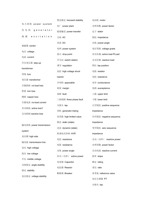
电力系统p o w e r s y s t e m 发电机g e n e r a t o r 励磁e x c i t a t i o n励磁器excitor电压voltage电流current升压变压器step-up transformer母线bus变压器transformer空载损耗no-load loss铁损iron loss铜损copper loss空载电流no-load current有功损耗active loss?无功损耗reactive loss输电系统power transmission system高压侧high side输电线transmission line高压high voltage低压low voltage中压middle voltage功角稳定angle stability稳定stability电压稳定voltage stability 暂态稳定transient stability电厂power plant能量输送power transfer交流AC直流DC电网power system落点drop point开关站switch station调节regulation高抗high voltage shuntreactor并列的apposable裕度margin故障fault三相故障three phase fault分接头tap切机generator triping高顶值high limited value静态static (state)动态dynamic (state)机端电压控制AVR电抗reactance电阻resistance功角power angle有功(功率)active power电容器Capacitor电抗器Reactor断路器Breaker电动机motor功率因数power-factor定子stator阻抗impedance功角power-angle电压等级voltage grade有功负载: active load PLoad无功负载reactive load档位tap position电阻resistor电抗reactance电导conductance电纳susceptance上限upper limit下限lower limit正序阻抗positive sequenceimpedance负序阻抗negative sequenceimpedance零序阻抗zero sequenceimpedance无功(功率)reactive power功率因数power factor无功电流reactive current斜率slope额定rating变比ratio参考值reference value电压互感器PT分接头tap仿真分析simulation analysis下降率droop rate传递函数transfer function框图block diagram受端receive-side同步synchronization保护断路器circuit breaker摇摆swing阻尼damping无刷直流电机Brusless DC motor刀闸(隔离开关) Isolator机端generator terminal变电站transformer substation 永磁同步电机Permanent-magnet Synchronism Motor异步电机Asynchronous Motor 三绕组变压器three-column transformer ThrClnTrans双绕组变压器double-column transformer DblClmnTrans固定串联电容补偿fixed series capacitor compensation双回同杆并架double-circuit lines on the same tower单机无穷大系统one machine - infinity bus system励磁电流Magnetizing current 补偿度degree of compensation电磁场:Electromagnetic fields 失去同步loss ofsynchronization装机容量installed capacity无功补偿reactive powercompensation故障切除时间fault clearingtime极限切除时间critical clearingtime强行励磁reinforced excitation并联电容器shunt capacitor<下降特性droop characteristics线路补偿器LDC(line dropcompensation)电机学Electrical Machinery自动控制理论AutomaticControl Theory电磁场Electromagnetic Field微机原理Principle ofMicrocomputer电工学Electrotechnics电路原理Principle of circuits电机学Electrical Machinery电力系统稳态分析?Steady-State Analysis ofPower System电力系统暂态分析Transient-State Analysis ofPower System?? 电力系统继电保护原理???????????????????????Principle of Electrical System'sRelay Protection?? 电力系统元件保护原理????Protection Principle ofPower System 's Element电力系统内部过电压????PastVoltage within Power system模拟电子技术基础??Basis ofAnalogue Electronic Technique数字电子技术????DigitalElectrical Technique?? 电路原理实验????? Lab. ofprinciple of circuits?? 电气工程讲座???Lectureson electrical power production电力电子基础???? Basicfundamentals of powerelectronics??高电压工程???High voltageengineering??电子专题实践Topics onexperimental project ofelectronics?? 电气工程概论Introductionto electrical engineering?? 电子电机集成系统??????????????????????????? Electronic machine system?? 电力传动与控制Electrical Drive and Control?? 电力系统继电保护Power System Relaying Protection ?? 主变压器???? main transformer?? 升压变压器???? step-up transformer?? 降压变压器???? step-down transformer ?? 工作变压器???? operating transformer ?? 备用变压器???? standby transformer?? 公用变压器???? common transformer?? 三相变压器???? three-phase transformer ?? 单相变压器???? single-phase transformer ?? 带负荷调压变压器?? ?? on-load regulating transformer?? 变压器铁芯???? transformer core?? 变压器线圈???? transformer coil?? 变压器绕组?? ?? transformer winding?? 变压器油箱???? transformer oil tank?? 变压器外壳???? transformer casing?? 变压器风扇???? transformer fan?? 变压器油枕???? transformer oilconservator(∽drum?? 变压器额定电压???? transformer reted voltage?? 变压器额定电流???? transformer reted current?? 变压器调压范围???? transformer voltageregulation rage?? 配电设备???? power distributionequipment?? SF6断路器???? SF6 circuit breaker?? 开关???? switch?? 按钮???? button?? 隔离开关???? isolator,disconnector?? 真空开关???? vacuum switch?? 刀闸开关???? knife-switch?? 接地刀闸???? earthing knife-switch?? 电气设备???? electrical equipment?? 变流器???? current converter?? 电流互感器???? current transformer?? 电压互感器???? voltage transformer?? 电源???? power source?? 交流电源???? AC power source?? 直流电源???? DC power source?? 工作电源???? operating source?? 备用电源???? Standby source?? 强电???? strong current?? 弱电???? weak current?? 继电器???? relay?? 信号继电器???? signal relay?? 电流继电器???? current relay?? 电压继电器???? voltage relay?? 跳闸继电器???? tripping relay?? 合闸继电器???? closing relay?? 中间继电器???? intermediate relay ?? 时间继电器???? time relay?? 零序电压继电器?? ?? zero-sequence voltage relay?? 差动继电器???? differential relay?? 闭锁装置???? locking device?? 遥控???? telecontrol?? 遥信???? telesignalisation?? 遥测???? telemetering?? 遥调???? teleregulation?? 断路器???? breaker,circuit breaker ?? 少油断路器?? ?? mini-oilbreaker,oil-mini-mum breaker?? 高频滤波器???? high-frequency filter?? 组合滤波器???? combined filter?? 常开触点???? normally opened contaact?? 常闭触点???? normally closed contaact?? 并联电容???? parallel capacitance?? 保护接地???? protective earthing?? 熔断器???? cutout,fusible cutout?? 电缆???? cable?? 跳闸脉冲???? tripping pulse?? 合闸脉冲???? closing pulse?? 一次电压???? primary voltage?? 二次电压???? secondary voltage?? 并联电容器???? parallel capacitor?? 无功补偿器???? reactive powercompensation device?? 消弧线圈???? arc-suppressing coil?? 母线???? Bus,busbar?? 三角接法???? delta connection?? 星形接法???? Wye connection?? 原理图???? schematic diagram?? 一次系统图???? primary system diagram?? 二次系统图???? secondary system diagram?? 两相短路???? two-phase short circuit?? 三相短路???? three-phase short circuit?? 单相接地短路???? single-phase ground shortcircuit?? 短路电流计算???? calculation of short circuitcurrent?? 自动重合闸???? automatic reclosing?? 高频保护???? high-freqency protection?? 距离保护???? distance protection?? 横差保护???? transverse differential protection?? 纵差保护???? longitudinal differential protection?? 线路保护???? line protection?? 过电压保护???? over-voltage protection ?? 母差保护???? bus differential protection ?? 瓦斯保护???? Buchholtz protection ?? 变压器保护???? transformer protection ?? 电动机保护???? motor protection?? 远方控制???? remote control?? 用电量???? power consumption?? 载波???? carrier?? 故障???? fault?? 选择性???? selectivity ?? 速动性???? speed?? 灵敏性???? sensitivity?? 可靠性???? reliability?? 电磁型继电器???? electromagnetic?? 无时限电流速断保护???? instantaneouslyover-current protection?? 跳闸线圈???? trip coil?? 工作线圈???? operating coil?? 制动线圈???? retraint coil?? 主保护???? main protection?? 后备保护???? back-up protection?? 定时限过电流保护???? definite time over-currentprotection?? 三段式电流保护???? the current protection withthree stages?? 反时限过电流保护???? inverse time over-currentprotection?? 方向性电流保护???? the directional currentprotection?? 零序电流保护???? zero-sequence currentprotection?? 阻抗???? impedance?? 微机保护???? Microprocessor Protection?AGC AutomaticGeneration Control 自动发电控制?AMR Automatic MessageRecording 自动抄表?ASS AutomaticSynchronized System 自动准同期装置?ATS Automatic TransformSystem 厂用电源快速切换装置?AVR Automatic VoltageRegulator 自动电压调节器?BCS Burner Control System燃烧器控制系统?BMS Burner ManagementSystem 燃烧器管理系统?CCS Coordinated ControlSystem 协调控制系统?CIS Consumer InformationSystem 用户信息系统?CRMS Control RoomManagement System 控制室管理系统?CRT Cathode Ray Tube 阴极射线管?DA Distribution Automation 配电自动化?DAS Data Acquisition System 数据采集与处理系统?DCS Distributed Control System 分散控制系统? DDC Direct Digital Control 直接数字控制(系统)? DEH Digital Electronic Hydraulic Control 数字电液(调节系统)?DMS Distribution Management System 配电管理系统?DPU Distributed Processing Unit 分布式处理单元? DSM Demand Side Management 需求侧管理? EMS Energy Management System 能量管理系统? ETS Emergency Trip System 汽轮机紧急跳闸系统?EWS Engineering Working Station 工程师工作站?FA Feeder Automation 馈线自动化?FCS Fieldbus Control System 现场总线控制系统? FSS Fuel Safety System 燃料安全系统?FSSS Furnace Safeguard Supervisory System 炉膛安全监控系统? FTU Feeder Terminal Unit馈线远方终端?GIS Gas InsulatedSwitchgear 气体绝缘开关设备?GPS Global PositionSystem 全球定位系统?HCS Hierarchical ControlSystem 分级控制系统?LCD Liquid Crystal Display液晶显示屏?LCP Local Control Panel 就地控制柜?MCC Motor Control Center(电动机)马达控制中心?MCS Modulating ControlSystem 模拟量控制系统?MEH Micro ElectroHydraulic Control System给水泵汽轮机电波控制系统?MIS ManagementInformation System 管理信息系统?NCS Net Control System网络监控系统?OIS Operator InterfaceStation 操作员接口站?OMS Outage ManagementSystem 停电管理系统?PAS Power ApplicationSoftware 电力应用软件?PID Proportion IntegrationDifferentiation 比例积分微分?PIO Process Input Output过程输入输出(通道)?PLC Programmable LogicalController 可编程逻辑控制器?PSS Power SystemStabilizator 电力系统稳定器?RTU Remote Terminal Unit站内远方终端?SA Substation Automation变电站自动化?SCADA SupervisoryControl And DataAcquisition 数据采集与监控系统?SCC Supervisory ComputerControl 监督控制系统?SCS Sequence ControlSystem 顺序(程序)控制系统?SIS Supervisory InformationSystem 监控信息系统?TDCS(TDC)Total DirectDigital Control 集散控制系统?TSI Turbine SupervisoryInstrumentation 汽轮机监测仪表?UPS Uninterrupted PowerSupply 不间断供电?WMS Work ManagementSystem 工作管理系统。
电气专业毕业设计外文翻译---快速交直流PWM整流感应发电机系统的高性能控制

中文4450字出处:Industry Applications, IEEE Transactions on, 2006, 42(5): 1146-1154.中文译文快速交—直流PWM整流感应发电机系统的高性能控制Jyoti Sastry, Olorunfemi Ojo, Zhiqiao Wu摘要:本篇主要描述了一种快速的交—直流感应发电机整流系统的直流电压调节控制方法,该整流系统中发电机的铜耗可减到最小。
通过输入输出线性化的补偿,使得同步参考结构中的等价模型体线性化、解耦,达到高性能的转速矢量控制。
稳态分解提供了发电机的操作规则,计算机仿真已证明了不同负载条件以及转速变化下的控制策略的有效性。
文章还展示了一些实验结果。
索引词:感应发电机,交—直流PWM整流器,励磁,输入输出线性化,巴特沃思多项式,磁饱和Ⅰ、绪论越来越多的研究和实际应用已转移到可再生能源系统,例如风能。
又由于发电机具有低成本,维护费用少,结构简单牢固,无刷(鼠笼式)等固有的优点,增加了感应电机特别是发电机的使用。
感应电机的转差率决定了它是以发电机还是电动机运转,正的转差率说明电机以电动机形式运转,而负的转差率标志着电机工作在发电状态。
众所周知,感应电机可以用作自激发电机,也就是说(a)通过定子接线端三个连接电容(b)通过使用反用换流器/整流器系统,发电机能够被励磁[1]。
在使用反用换流器/整流器系统的情况下,直流侧的电容是否作为三相电容取决于反用换流器的开关信号,整流器的单相直流电容给感应电机提供必需的励磁。
大量广泛的观察说明,过去超过25年里在自激,电压组合建模,感应电机的稳态分析等不同领域所做的大量工作已经被展示在[2]。
而且,在以前的出版著作中,描述过感应发电机整流系统的矢量控制。
该系统用于产生直流而且它的整流器也提供励磁[3]。
该系统特别适用于风能方面的研究应用,因此来研究变化的转子转速的反应控制器。
[4]中也做了感应发电机—整流器在方向场控制下的稳定性研究,强调了感应发电机在高速应用时存在可能的不稳定性。
电力系统自动化毕业论文中英文资料外文翻译

毕业设计(论文)外文资料翻译专业名称:电力系统自动化英文资料:INDUCTION MOTOR STARTING METHODSAbstract -Many methods can be used to start large AC induction motors. Choices such as full voltage, reduced voltage either by autotransformer or Wyes - Delta, a soft starter, or usage of an adjustable speed drive can all have potential advantages and trade offs. Reduced voltage starting can lower the starting torque and help prevent damage to the load. Additionally, power factor correction capacitors can be used to reduce the current, but care must be taken to size them properly. Usage of the wrong capacitors can lead to significant damage. Choosing the proper starting method for a motor will include an analysis of the power system as well as the starting load to ensure that the motor is designed to deliver the needed performance while minimizing its cost. This paper will examine the most common starting methods and their recommended applications.I. INTRODUCTIONThere are several general methods of starting induction motors: full voltage, reduced voltage, wyes-delta, and part winding types. The reduced voltage type can include solid state starters, adjustable frequency drives, and autotransformers. These, along with the full voltage, or across the line starting, give the purchaser a large variety of automotives when it comes to specifying the motor to be used in a given application. Each method has its own benefits, as well as performance trade offs. Proper selection will involve a thorough investigation of any power system constraints, the load to be accelerated and the overall cost of the equipment.In order for the load to be accelerated, the motor must generate greater torque than the load requirement. In general there are three points of interest on the motor's speed-torque curve. The first is locked-rotor torque (LRT) which is the minimum torque which the motor will develop at rest for all angular positions of the rotor. The second is pull-up torque (PUT) which is defined as the minimum torque developed by the motor during the period of acceleration from rest to the speed at which breakdown torque occurs. The last is the breakdown torque (BDT) which is defined as the maximum torque which the motor will develop. If any of these points are below the required load curve, then the motor will not start.The time it takes for the motor to accelerate the load is dependent on the inertia of the load and the margin between the torque of the motor and the load curve, sometimes called accelerating torque. In general, the longer the time it takes for the motor to accelerate the load, the more heat that will be generated in the rotor bars, shorting ring and the stator winding. This heat leads to additional stresses in these parts and can have an impaction motor life.II. FULL VOLTAGEThe full voltage starting method, also known as across the line starting, is the easiest method to employ, has the lowest equipment costs, and is the most reliable. This method utilizes a control to close a contactor and apply full line voltage to the motor terminals. This method will allow the motor to generate its highest starting torque and provide the shortest acceleration times.This method also puts the highest strain on the power system due to the high starting currents that can be typically six to seven times the normal full load current of the motor. If the motor is on a weak power system, the sudden high power draw can cause a temporary voltage drop, not only at the motor terminals, but the entire power bus feeding the starting motor. This voltage drop will cause a drop in the starting torque of the motor, and a drop in the torque of any other motor running on the power bus. The torque developed by an induction motor varies roughly as the square of the applied voltage. Therefore, depending on the amount of voltage drop, motors running on this weak power bus could stall. In addition, many control systems monitor under voltage conditions, a second potential problem that could take a running motor offline during a full voltage start. Besides electrical variation of the power bus, a potential physical disadvantage of an across the line starting is the sudden loading seen by the driven equipment. This shock loading due to transient torques which can exceed 600% of the locked rotor torque can increase the wear on the equipment, or even cause a catastrophic failure if the load can not handle the torques generated by the motor during staring.A. Capacitors and StartingInduction motors typically have very low power factor during starting and as a result have very large reactive power draw. See Fig. 2. This effect on the system can be reduced by adding capacitors to the motor during starting.The large reactive currents required by the motor lag the applied voltage by 90 electrical degrees. This reactive power doesn't create any measurable output, but is rather the energy required for the motor to function. The product of the applied system voltage and this reactive power component can be measured in V ARS (volt-ampere reactive). The capacitors act to supply a current that leads the applied voltage by 90 electrical degrees. The leading currents supplied by the capacitors cancel the laggingcurrent demanded by the motor, reducing the amount of reactive power required to be drawn from the power system.To avoid over voltage and motor damage, great care should be used to make sure that the capacitors are removed as the motor reaches rated speed, or in the event of a loss of power so that the motor will not go into a generator mode with the magnetizing currents provided from the capacitors. This will be expanded on in the next section and in the appendix.B. Power Factor CorrectionCapacitors can also be left permanently connected to raise the full load power factor. When used in this manner they are called power factor correction capacitors. The capacitors should never be sized larger than the magnetizing current of the motor unless they can be disconnected from the motor in the event of a power loss.The addition of capacitors will change the effective open circuit time constant of the motor. The time constant indicates the time required for remaining voltage in the motor to decay to 36.8% of rated voltage after the loss of power. This is typically one to three seconds without capacitors.With capacitors connected to the leads of the motor, the capacitors can continue to supply magnetizing current after the power to the motor has been disconnected. This is indicated by a longer time constant for the system. If the motor is driving a high inertia load, the motor can change over to generator action with the magnetizingCurrent from the capacitors and the shaft driven by the load. This can result in the voltage at the motor terminals actually rising to nearly 50% of rated voltage in some cases. If the power is reconnected before this voltage decays severe transients can be created which can cause significant switching currents and torques that can severely damage the motor and the driven equipment. An example of this phenomenon is outlined in the appendix.Ⅲ. REDUCED VOLTAGEEach of the reduced voltage methods are intended to reduce the impact of motor starting current on the power system by controlling the voltage that the motor sees atthe terminals. It is very important to know the characteristics of the load to be started when considering any form of reduced voltage starting. The motor manufacturer will need to have the speed torque curve and the inertia of the driven equipment when they validate their design. The curve can be built from an initial, or break away torque, as few as four other data points through the speed range, and the full speed torque for the starting condition. A centrifugal or square curve can be assumed in many cases, but there are some applications where this would be problematic. An example would be screw compressors which have a much higher torque requirement at lower speeds than the more common centrifugal or fan load. See Fig. 3. By understanding the details of the load to be started the manufacturer can make sure that the motor will be able to generate sufficient torque to start the load, with the starting method that is chosen.A. AutotransformerThe motor leads are connected to the lower voltage side of the transformer. The most common taps that are used are 80%, 65%, and 50%. At 50% voltage the current on the primary is 25% of the full voltage locked rotor amps. The motor is started with this reduced voltage, and then after a pre-set condition is reached the connection is switched to line voltage. This condition could be a preset time, current level, bus volts, or motor speed. The change over can be done in either a closed circuit transition, or an open circuit transition method. In the open circuit method the connection to the voltage is severed as it is changed from the reduced voltage to the line level. Care should be used to make sure that there will not be problems from transients due to the switching. This potential problem can be eliminated by using the closed circuit transition. With the closed circuit method there is a continuousVoltage applied to the motor. Another benefit with the autotransformer starting is in possible lower vibration and noise levels during starting.Since the torque generated by the motor will vary as the square of the applied voltage, great care should be taken to make sure that there will be sufficient accelerating torque available from the motor. A speed torque curve for the driven equipment along with the inertia should be used to verify the design of the motor. A good rule of thumb is to have a minimum of 10% of the rated full load torque of the motor as a margin at all points of the curve.Additionally, the acceleration time should be evaluated to make sure that the motor has sufficient thermal capacity to handle the heat generated due to the longeracceleration time.B. Solid State or Soft StartingThese devices utilize silicon controlled rectifiers or Scars. By controlling the firing angle of the SCR the voltage that the device produces can be controlled during the starting of the motor by limiting the flow of power for only part of the duration of the sine wave.The most widely used type of soft starter is the current limiting type. A current limit of 175% to 500% of full load current is programmed in to the device. It then will ramp up the voltage applied to the motor until it reaches the limit value, and will then hold that current as the motor accelerates.Tachometers can be used with solid state starters to control acceleration time. Voltage output is adjusted as required by the starter controller to provide a constant rate of acceleration.The same precautions in regards to starting torque should be followed for the soft starters as with the other reduced voltage starting methods. Another problem due to the firing angle of the SCR is that the motor could experience harmonic oscillating torques. Depending on the driven equipment, this could lead to exciting the natural frequency of the system.C. Adjustable Frequency DrivesThis type of device gives the greatest overall control and flexibility in starting induction motors giving the most torque for an amount of current. It is also the most costly.The drive varies not only the voltage level, but also the frequency, to allow the motor to operate on a constant volt per hertz level. This allows the motor to generate full load torque throughout a large speed range, up to 10:1. During starting, 150% of rated current is typical.This allows a significant reduction in the power required to start a load and reduces the heat generated in the motor, all of which add up to greater efficiency. Usage of the AFD also can allow a smaller motor to be applied due to the significant increase of torque available lower in the speed range. The motor should still be sizedlarger than the required horsepower of the load to be driven. The AFD allows a great degree of control in the acceleration of the load that is not as readily available with the other types of reduced voltage starting methods.The greatest drawback of the AFD is in the cost relative to the other methods. Drives are the most costly to employ and may also require specific motor designs to be used. Based on the output signal of the drive, filtered or unfiltered, the motor could require additional construction features. These construction features include insulated bearings, shaft grounding brushes, and insulated couplings due to potential shaft current from common mode voltage. Without these features, shaft currents, which circulate through the shaft to the bearing, through the motor frame and back, create arcing in the bearings that lead to premature bearing failure, this potential for arcing needs to be considered when applying a motor/drive package in a hazardous environment, Division2/Zone2.An additional construction feature of a motor used on an AFD may require is an upgraded insulation system on the motor windings. An unfiltered output signal from a drive can create harmonic voltage spikes in the motor, stressing the insulation of the motor windings.It is important to note that the features described pertain to motors which will be started and run on an AFD. If the drive is only used for starting the motor, these features may not be necessary. Consult with the motor manufacturer for application specific requirements.D. Primary Resistor or Reactor StartingThis method uses either a series resistor or reactor bank to be placed in the circuit with the motor. Resistor starting is more frequently used for smaller motors.When the motor is started, the resistor bank limits the flow of inrush current and provides for a voltage drop at the motor terminals. The resistors can be selected to provide voltage reductions up to 50%. As the motor comes up to speed, it develops a counter EMF (electro-magnetic field) that opposes the voltage applied to the motor. This further limits the inrush currents. As the inrush current diminishes, so does t>e voltage drop across the resistor bank allowing the torque generated by the motor to increase. At a predetermined time a device will short across the resistors and open the starting contactor effectively removing the resistor bank from the circuit. This provides for a closed transition and eliminates the concerns due to switchingtransients.Reactors will tend to oppose any sudden changes in current and therefore act to limit the current during starting. They will remain shorted after starting and provide a closed transition to line voltage.E .Star delta StartingThis approach started with the induction motor, the structure of each phase of the terminal are placed in the motor terminal box. This allows the motor star connection in the initial startup, and then re-connected into a triangle run. The initial start time when the voltage is reduced to the original star connection, the starting current and starting torque by 2 / 3. Depending on the application, the motor switch to the triangle in the rotational speed of between 50% and the maximum speed. Must be noted that the same problems, including the previously mentioned switch method, if the open circuit method, the transition may be a transient problem. This method is often used in less than 600V motor, the rated voltage 2.3kV and higher are not suitable for star delta motor start method.Ⅴ. INCREMENT TYPEThe first starting types that we have discussed have deal with the way the energy is applied to the motor. The next type deals with different ways the motor can be physically changed to deal with starting issues.Part WindingWith this method the stator of the motor is designed in such a way that it is made up of two separate windings. The most common method is known as the half winding method. As the name suggests, the stator is made up of two identical balanced windings. A special starter is configured so that full voltage can be applied to one half of the winding, and then after a short delay, to the second half. This method can reduce the starting current by 50 to 60%, but also the starting torque. One drawback to this method is that the motor heating on the first step of the operation is greater than that normally encountered on across-the-line start. Therefore the elapsed time on the first step of the part winding start should be minimized. This method also increases the magnetic noise of the motor during the first step.IV .ConclusionThere are many ways asynchronous motor starting, according to the constraints of power systems, equipment costs, load the boot device to select the best method. From the device point of view, was the first full-pressure launch the cheapest way, but it may increase the cost efficiency in the use of, or the power supply system in the region can not meet their needs. Effective way to alleviate the buck starts the power supply system, but at the expense of the cost of starting torque.These methods may also lead to increased motor sizes have led to produce the required load torque. Inverter can be eliminated by the above two shortcomings, but requires an additional increase in equipment costs. Understand the limitations of the application, and drives the starting torque and speed, allowing you for your application to determine the best overall configuration.英文资料翻译:异步电动机起动的方法摘要:大容量的交流异步电动机有多种启动方法。
- 1、下载文档前请自行甄别文档内容的完整性,平台不提供额外的编辑、内容补充、找答案等附加服务。
- 2、"仅部分预览"的文档,不可在线预览部分如存在完整性等问题,可反馈申请退款(可完整预览的文档不适用该条件!)。
- 3、如文档侵犯您的权益,请联系客服反馈,我们会尽快为您处理(人工客服工作时间:9:00-18:30)。
Translated from: XiongFusheng, DC Switching Power Supply Protection Technology, Guangzhou:The World of Power Supply [P],2002.2.DC Switching Power Supply Protection TechnologyAbstract: The DC switching power supply protection system, protection system design principles and machine protection measures, an analysis of switching power supply in the range of protected characteristics and its design methodology,introduced a number of practical protection circuit.Keywords: switching power supply protection circuit system design1、IntroductionDC switching regulator used in the price of more expensive high-power switching devices, the control circuit is also more complex, In addition, the load switching regulators are generally used a large number of highly integrated electronic systems installed devices. Transistors and integrated device tolerance electricity, less heat shocks. Switching Regulators therefore should take into account the protection of voltage regulators and load their own safety. Many different types of circuit protection, polarity protection, introduced here, the program protection, over-current protection, over-voltage protection, under-voltage protection and over-temperature protection circuit. Usually chosen to be some combination of protection, constitutes a complete protection system.2、polarity protectionDC switching regulator input are generally not regulated DC power supply. Operating errors or accidents as a result of the situation will take its wrong polarity, switching power supply will be damaged. Polarity protection purposes, is to make the switching regulator only when the correct polarity is not connected to DC power supply regulator to work at. Connecting a single device can achieve power polarity protection. Since the diode D to flow through switching regulator input total current, this circuit applied in a low-power switching regulator more suitable. Power in the larger occasion, while the polarity protection circuit as a procedure to protect a link, save the power required for polarity protection diodes, power consumption will be reduced. In order to easy to operate, make it easier to identify the correct polarity or not, collect the next light.3、procedures to protectSwitching power supply circuit is rather complicated, basically can be divided into low-power and high-power part of the control part of the switch. Switch is a high-power transistors, for the protection of the transistor switch is turned on or off power safety, we must first modulator, amplifier and other low-power control circuit. To this end, the boot to ensure the correct procedures. Switching Regulators generally take the input of a small inductor, the input filter capacitor. Moment in the boot, filter capacitor will flow a lot of surge current, the surge current can be several times more than the normal input current. Such a large surge current may contact the general power switch or relay contact melting, and the input fuse fuse. In addition, the capacitor surge current will damage to shorten the life span of premature damage. To this end, the boot should be access to a current limiting resistor, through the current limiting resistor to capacitor charging. In order not to make the current limiting resistor excessive power consumption, thus affecting the normal switching regulator, and the transient process in the boot after a short period then automatically relays it to DC power supply directly to the switching regulator power supply. This circuit switching regulator called a "soft start" circuit.Switching regulator control circuit of the logic components required or op-amp auxiliary power supply. To this end, the auxiliary power supply must be in the switch circuit. This control circuit can be used to ensure the boot. Normal boot process is: to identify the polarity of input power, voltage protection procedures → boot → auxiliary power supply circuit and through current limiting resistor R of the switching regulator input capacitor C → charge modulation switching regul ator circuit, → short-circuit current limiting resistor stability switching regulator.In the switching regulator, the machines just because the output capacitance, and charge to the rated output voltage value of the need for a certain period of time. During this time, sampling the output amplifier with low input voltage sampling, closed-loop regulation characteristics of the system will force the switching of the transistor conduction time lengthened, so that switching transistor during this period will tend to continuous conduction, and easily damaged. To this end, the requirements of this paragraph in the boot time, the switch to switch the output modulation circuit transistor base drive signal of the pulse width modulation, can guarantee the switching transistor by the cut-off switches are becomingmore and more normal state, therefore the protection of the setting up of a boot to tie in with the soft start.4、over-current protectionWhen the load short-circuit, overload control circuit failure or unforeseen circumstances, such as would cause the flow of switching voltage regulator transistor current is too large, so that increased power tubes, fever, if there is no over-current protection device, high power switching transistor may be damaged. Therefore, the switching regulator in the over-current protection is commonly used. The most economical way is to use simple fuse. As a result of the heat capacity of small transistors, general fuse protection in general can not play a role in the rapid fuse common fuse. This method has the advantage of the protection of vulnerable, but it needs to switch transistor in accordance with specific security requirements of the work area to select the fuse specifications. This disadvantage is over-current protection measures brought about by the inconvenience of frequent replacement of fuses.Linear voltage regulator commonly used in the protection and current limiting to protect the cut-off in the switching regulator can be applied. However, according to the characteristics of switching regulators, the protection circuit can not directly control the output transistor switches, and overcurrent protection must be converted to pulse output commands to control the modulator to protect the transistor switch. In order to achieve over-current protection are generally required sampling resistor in series in the circuit, this will affect the efficiency of power supply, so more for low-power switching regulator of occasions. In the high-power switching power supply, by taking into account the power consumption should be avoided as far as possible access to the sampling resistor. Therefore, there will usually be converted to over-current protection, and under-voltage protection.5、over-voltage protectionSwitching regulator's input over-voltage protection, including over-voltage protection and output over-voltage protection. Switching regulator is not used in DC power supply voltage regulator and rectifier, such as battery voltage, if too high, so switching regulator is not working properly, or even damage to internal devices, therefore, it is necessary to use the input over-voltage protection circuit. Using transistors and relays protection circuit.In the circuit, when the input DC power supply voltage higher than the voltage regulator diode breakdown voltage value, the breakdown voltage regulator tube, a currentflowing through resistor R, so that V turn-on transistor, relay, normally closed contact off open, cut off the input. Voltage regulator voltage regulator which controls the value of Vz = ESrmax-UBE. The polarity of input power with the input protection circuit can be combined with over-voltage protection, polarity protection constitute a differential circuit and overvoltage protection.Output over-voltage protection switching power supply is essential. In particular, for the 5V output of the switching regulator, it is a lot of load on a high level of integration of the logic device. If at work, switching regulator sudden damage to the switch transistor, the output potential may be increased immediately to the importation of non-regulated DC power supply voltage value, causing great loss instantaneous. Commonly used method is short-circuit protection thyristor. The simplest over-voltage protection circuit. When the output voltage is too high, the regulator tube breakdown triggered thyristor turn-on, the output short-circuit, resulting in over-current through the fuse or circuit protective device to cut off the input to protect the load. This circuit is equivalent to the response time of the opening time of thyristor is about 5 ~ 10μs. The disadvantage is that its action is fixed voltage, temperature coefficient, and action points of instability. In addition, there is a voltage regulator control parameters of the discrete, model over-voltage start-up the same but has different values, difficult to debug. Esc a sudden increase in output voltage, transistors V1, V2 conduction, the thyristor conduction. Reference voltage Vz by type.6、under-voltage protectionOutput voltage below the value to reflect the input DC power supply, switching regulator output load internal or unusual occurrence. Input DC power supply voltage drops below the specified value would result in switching regulator output voltage drops, the input current increases, not only endanger the switching transistor, but also endanger the input power. Therefore, in order to set up due to voltage protection. Due to simple voltage protection.When no voltage regulator input normal, ZD breakdown voltage regulator tube, transistors V conduction, the relay action, contact pull-in, power-switching regulator. When the input below the minimum allowable voltage value, the regulator tube ZD barrier, V cut-off, contact Kai-hop, switching regulator can not work. Internal switching regulator, as the control switch transistor circuit disorders or failure will decrease the output voltage; load short-circuit output voltage will also decline.Especially in the reversed-phase step-up or step-up switching regulator DC voltage of the protection due to over-current protection with closely related and therefore more important. Implementation of Switching Regulators in the termination of the output voltage comparators.Normally, there is no comparator output, once the voltage drops below the allowable value in the comparator on the flip, drive alarm circuit; also fed back to the switching regulator control circuit, so that switching transistor cut-off or cut off the input power.7、over-temperature protectionSwitching regulator and the high level of integration of light-weight small volume, with its unit volume greatly increased the power density, power supply components to its work within the requirements of the ambient temperature is also a corresponding increase. Otherwise, the circuit performance will deteriorate, premature component failure. Therefore, in high-power switching regulator should be set up over-temperature protection.Relays used to detect the temperature inside the power supply temperature, when the internally generated power supply overheating, the temperature of the relay on the action, so that whole circuit in a warning alarm, and the realization of the power supply over-temperature protection. Temperature relay can be placed in the vicinity of the switching transistor, the general high-power tube shell to allow the maximum temperature is 75 ℃, adjust the temperature setting to 60 ℃. When the shell after the temperature exceeds the allowable value to cut off electrical relay on the switch protection. Semiconductor switching device thermal "hot thyristor," in the over-temperature protection, played an important role. It can be used as directed circuit temperature. Under the control of p-hot-gate thyristor (TT102) characteristics, by RT value to determine the temperature of the device turn-on, RT greater the temperature the lower the turn-on. When placed near the power switching transistor or power device, it will be able to play the role of temperature instructions. When the power control the temperature of the shell or the internal device temperature exceeds the allowed value, the heat conduction thyristor on, so that LED warning light. If the optocoupler with, would enable the whole circuit alarm action to protect the switching regulator. It can also be used as a power transistor as the over-temperature protection, crystal switch the base current by n-type gate control thyristor TT201 thermal bypass, cut-off switch to cut off the collector current to prevent overheating.8、ConclusionDiscussed above in the switching regulator of a variety of conservation, and introduces a number of specific ways to achieve. Of a given switching power supply is concerned, but also protection from the whole to consider the following points:1)the switching regulator used in the switching transistor in the DC security restrictions on the work of regional work. The transistor switches selected by the manual available transistors get DC safe working area. According to the maximum collector current to determine the input value of over-current protection. However, the instantaneous maximum value should be converted to the average current. At rated output current and output voltage conditions, the switch of the dynamic load line does not exceed a safe working area DC maximum input voltage, input over-voltage protection is the voltage value.2) the switching regulator output limit given by the technical indicators within. Work within the required temperature range, the switching regulator's output voltage, the lower limit of the output is off, due to the voltage value of voltage protection. Over-current protection can be based on the maximum output current to determine. False alarm in order not to protect the value of a certain margin to remain appropriate.3)from the above two methods to determine the protection after the power supply device in accordance with the needs of measures to determine the alarm. Measures the general alarm sound and light alarm two police. Voice of the police applied to more complex machines, power supply parts and do not stand out in a place, it can give staff an effective warning of failure; optical Police instructions can be eye-catching and fault alarm and pointed out that the fault location and type. Protection measures should be protected as to determine the location. In the high-power, multi-channel power supply, always paying, DC circuit breakers, relays, etc. high-sensitivity auto-protection measures, to cut off the input power supply to stop working the system from damage. Through the logic control circuit to make the appropriate program cut-off switch transistor is sensitive it is convenient and economic. This eliminated large, long response time, the price of your high-power relay or circuit breaker.4) the power of putting in the protection circuit will be affected after the reliability of the system, for which want to protect the reliability of the circuit itself is higher in order to improve the reliability of the entire power system, thereby increasing its own power supply MTBF. This requires the protection of strict logic, the circuit is simple, at least components,In addition to the protection circuit should also be considered a failure of maintenance of their difficulty and their power to protect the damage.Therefore, we must be comprehensive and systematic consideration of a variety of switching power supply protection measures to ensure the normal operation of switching power supplies and high-efficiency and high reliability.译自:熊福生,直流开关电源保护技术,广州:电源世界期刊[P],2002.2直流开关稳压电源的保护技术摘要:讨论了直流开关稳压电源的保护系统,提出保护系统设计的原则和整机保护的措施,分析了开关稳压电源中的各种保护的特点及其设计方法,介绍了几种实用保护电路。