外文翻译-扩频通信系统及MATLAB仿真
毕业设计外文翻译-基于MATLAB的TD-SCDMA通信系统的调制与解调仿真程序设计
Review of UMTS1.1 UMTS Network ArchitectureThe European/Japanese 3G standard is referred to as UMTS. UMTS is one of a number of standards ratified by the ITU-T under the umbrella of IMT-2000. It is currently the dominant standard, with the US CDMA2000 standard gaining ground, particularly with operators that have deployed cdmaOne as their 2G technology. At time of writing,Japan is the most advanced in terms of 3G network deployment. The three incumbent operators there have implemented three different technologies: J-Phone is using UMTS,KDDI has a CDMA2000 network, and the largest operator NTT DoCoMo is using a system branded as FOMA (Freedom of Multimedia Access). FOMA is based on the original UMTS proposal, prior to its harmonization and standardization.The UMTS standard is specified as a migration from the second generation GSM standard to UMTS via the General Packet Radio System (GPRS) and Enhanced Data for Global Evolution (EDGE), as shown in Figure. This is a sound rationale since as of April 2003, there were over 847 Million GSM subscribers worldwide1, accounting for68% of the global cellular subscriber figures. The emphasis is on keeping as much ofthe GSM network as possible to operate with the new system.We are now well on the road towards Third Generation (3G), where the network will support all traffic types: voice, video and data, and we should see an eventual explosion in the services available on the mobile device. The driving technology for this is the IP protocol. Many cellular operators are now at a position referred to as 2.5G, with the deployment of GPRS, which introduces an IP backbone into the mobile core network.The diagram below, Figure 2, shows an overview of the key components in a GPRS network, and how it fits into the existing GSM infrastructure.The interface between the SGSN and GGSN is known as the Gn interfaceand uses the GPRS tunneling protocol (GTP, discussed later). The primary reason for the introduction of this infrastructure is to offer connections to external packet networks, such as the Internet or a corporate Intranet.This brings the IP protocol into the network as a transport between the SGSN and GGSN. This allows data services such as email or web browsing on the mobile device,with users being charged based on volume of data rather than time connected.The dominant standard for delivery of 3G networks and services is the Universal Mobile Telecommunications System, or UMTS. The first deployment of UMTS is the Release ’99 architecture, shown below in Figure 3.In this network, the major change is in the radio access network (RAN) with the introduction of CDMA technology for the air interface, and ATM as a transport in the transmission part. These changes have been introduced principally to support the transport of voice, video and data services on the same network. The core network remains relatively unchanged, with primarily software upgrades. However, the IP protocol pushes further into the network with the RNC now communicating with the 3G SGSN using IP.The next evolution step is the Release 4 architecture, Figure 4. Here, the GSM core is replaced with an IP network infrastructure based around V oice over IP technology.The MSC evolves into two separate components: a Media Gateway (MGW) and an MSC Server (MSS). This essentially breaks apart the roles of connection and connection control. An MSS can handle multiple MGWs, making the network more scaleable.Since there are now a number of IP clouds in the 3G network, it makes sense to merge these together into one IP or IP/ATM backbone (it is likely both options will be available to operators.) This extends IP right across the whole network, all the way to the BTS.This is referred to as the All-IP network, or the Release 5 architecture, as shown in Figure 5. The HLR/VLR/EIR are generalised and referred to as the HLR Subsystem(HSS).Now the last remnants of traditional telecommunications switching are removed, leaving a network operating completely on the IP protocol, and generalised for the transport of many service types. Real-time services are supported through the introduction of a new network domain, the IP Multimedia Subsystem (IMS).Currently the 3GPP are working on Release 6, which purports to cover all aspects not addressed in frozen releases. Some call UMTS Release 6 4G and it includes such issues as interworking of hot spot radio access technologies such as wireless LAN1.2 UMTS FDD and TDDLike any CDMA system, UMTS needs a wide frequency band in which to operate to effectively spread signals. The defining characteristic of the system is the chip rate, where a chip is the width of one symbol of the CDMA code. UMTS uses a chip rate of 3.84Mchips/s and this converts to a required spectrum carrier of 5MHz wide. Since this is wider than the 1.25MHz needed for the existi ng cdmaOne system, the UMTS air interface is termed ‘wideband’ CDMA.There are actually two radio technologies under the UMTS umbrella: UMTS FDD and TDD. FDD stands for Frequency Division Duplex, and like GSM, separates traffic in the uplink and downlink by placing them at different frequency channels. Therefore an operator must have a pair of frequencies allocated to allow them to run a network, hence the term ‘paired spectrum’. TDD or Time Division Duplex requires only one frequency channel, and uplink and downlink traffic are separated by sending them at different times. The ITU-T spectrum usage, as shown in Figure 6, for FDD is 1920- 980MHz for uplink traffic, and 2110-2170MHz for downlink. The minimum allocation an operator needs is two paired 5MHz channels, one for uplink and one for downlink, at a separation of 190MHz. However, to provide comprehensive coverage and services, it is recommended that an operator be given three channels. Considering the spectrum allocation, there are 12 paired channels available, and many countries have now completed the licencing process for this spectrum, allocating between two and four channels per licence. This has tended to workout a costly process for operators, since the regulatory authorities in some countries, notably in Europe, have auctioned these licences to the highest bidder. This has resulted in spectrum fees as high as tens of billions of dollars in some countries.The Time Division Duplex (TDD) system, which needs only one 5MHz band in which to operate, often referred to as unpaired spectrum. The differences between UMTS FDD and TDD are only evident at the lower layers, particularly on the radio interface. At higher layers, the bulk of the operation of the two systems is the same. As the name suggests, the TDD system separates uplink and downlink traffic by placing them in different time slots. As will be seen later, UMTS uses a 10ms frame structure which is divided into 15 equal timeslots. TDD can allocate these to be either uplink or downlink,with one or more breakpoints between the two in a frame defined. In this way, it is well suited to packet traffic, since this allows great flexibility in dynamically dimensioning for asymmetry in traffic flow.The TDD system should not really be considered as an independent network, but rather as a supplement for an FDD system to provide hotspot coverage at higher data rates. It is rather unsuitable for large scale deployment due to interference between sites, since a BTS may be trying to detect a weak signal from a UE, which is blocked out by a relatively strong signal at the same frequency from a nearby BTS. TDD is ideal for indoor coverage over small areas.Since FDD is the main access technology being developed currently, the explanations presented here will focus purely on this system.1.3 UMTS Bearer ModelThe procedures of a mobile device connecting to a UMTS network can be split into two areas: the access stratum (AS) and the non-access stratum (NAS). The access stratum involves all the layers and subsystems that offer general services to the non-access stratum. In UMTS, the access stratum consists of all of the elements in the radio access network, including the underlying ATMtransport network, and the various mechanisms such as those to provide reliable information exchange. All of the non-access stratum functions are those between the mobile device and the core network, for example, mobility management. Figure 7 shows the architecture model. The AS interacts with the NAS through the use of service access points (SAPs).UMTS radio access network (UTRAN) provides this separation of NAS and AS functions, and allows for AS functions to be fully controlled and implemented within the UTRAN. The two major UTRAN interfaces are the Uu, which is the interface between the mobile device, or User Equipment (UE) and the UTRAN, and the Iu, which is the interface between the UTRAN and the core network. Both of these interfaces can be divided into control and user planes each with appropriate protocol functions.A Bearer Service is a link between two points, which is defined by a certain set of characteristics. In the case of UMTS, the bearer service is delivered using radio access bearers.A Radio access bearer (RAB) is defined as the service that the access stratum (i.e.UTRAN) provides to the non-access stratum for transfer of user data between the User Equipment and Core Network. A RAB can consist of a number of subflows, which are data streams to the core network within the RAB that have different QoS characteristics,such as different reliabilities. A common example of this is different classes of bits with different bit error rates can be realised as different RAB subflows. RAB subflows are established and released at the time the RAB is established and released, and are delivered together over the same transport bearer.A Radio Link is defined as a logical association between a single User Equipment (UE) and a single UTRAN access point, such as an RNC. It is physically comprised of one or more radio bearers and should not be confused with radio access bearer.Looking within the UTRAN, the general architecture model is as shown in Figure 8 below. Now shown are the Node B or Base Station (BTS) and RadioNetwork Controller (RNC) components, and their respective internal interfaces. The UTRAN is subdivided into blocks referred to as Radio Network Subsystems (RNS), where each RNS consists of one controlling RNC (CRNC) and all the BTSs under its control. Unique to UMTS is the interface between RNSs, the Iur interface, which plays a key role in handover procedures. The interface between the BTS and RNC is the Iub interface.All the ‘I’ interfaces: Iu, Iur and Iub, currently3 use ATM as a transport layer. In the context of ATM, the BTS is seen as a host accessing an ATM network, within which the RNC is an ATM switch. Therefore, the Iub is a UNI interface, whereas the Iu and Iur interfaces are considered to be NNI, as illustrated in Figure 9.This distinction is because the BTS to RNC link is a point-to-point connection in that a BTS or RNC will only communicate with the RNC or BTS directly connected to it, and will not require communication beyond that element to another network element.For each user connection to the core network, there is only one RNC, which maintains the link between the UE and core network domain, as highlighted in Figure 10. This RNC is referred to as the serving RNC or SRNC. That SRNC plus the BTSs under its control is then referred to as the SRNS. This is a logical definition with reference to that UE only. In an RNS, the RNC that controls a BTS is known as the controlling RNC or CRNC. This is with reference to the BTS, cells under its control and all the common and shared channels within.As the UE moves, it may perform a soft or hard handover to another cell. In the case of a soft handover, the SRNC will activate the new connection to the new BTS. Should the new BTS be under the control of another RNC, the SRNC will also alert this new RNC to activate a connection along the Iur interface. The UE now has two links, one directly to the SRNC, and the second, through the new RNC along the Iur interface. In this case, this new RNC is logically referred to as a drift RNC or DRNC, see Figure 10. It is not involved in any processing of the call and merely relays it to the SRNC for connection to the core. In summary,SRNC and DRNC are usually associated with the UE and the CRNC is associated with the BTS. Since these are logical functions it is normal practice that a single RNC is capable of dealing with all these functions.A situation may arise where a UE is connected to a BTS for which the SRNC is not the CRNC for that BTS. In that situation, the network may invoke the Serving RNC Relocation procedure to move the core network connection. This process is described inSection 3.通用移动通信系统的回顾1.1 UMTS网络架构欧洲/日本的3G标准,被称为UMTS。
基于matlab的直序扩频通信系统的仿真设计
基于matlab的直序扩频通信系统的仿真摘要根据扩频理论,用MATLAB对直接序列扩频通信系统进行了仿真。
根据香农定理和科捷尔尼科夫潜在抗干扰理论,通过MATLAB的仿真平台对直扩通信系统进行了仿真,建立了扩频通信系统仿真模型,详细讲述了各个模块的设计,接收端同步捕获过程采用数字匹配滤波器的原理。
在给定的仿真条件下,对仿真程序进行了运行测试,得到了预期的仿真结果。
关键词:直接序列扩频;通信;MATLABDirect sequence spread spectrum communication system basedon matlab simulationAbstractIn this paper, based on the spread spectrum theory, I use MATLAB to simulate the direct sequence spread spectrum.According to the shannon theorem and jie's nico's potential interference theory, direct sequence spread spectrum is simulated by the simulation platform which is offered by MATLAB. And it tells the story of the design of various modules in detail. The receiver synchronization capture process adopts the principle of digital matched filter. In a given simulation conditions, I run the test simulation program and get the expectant simulation results.Key Words:direct sequence spread spectrum, communication, MATLAB目录1绪论31.1 扩频通信的概述31.2扩频通信的发展与应用32 直接序列扩频通信52.1理论基础52.2扩频通信系统的指标62.3扩频通信的种类72.4直接序列扩频通信系统72.5 扩频序列122.6 扩频序列的同步捕获162.6.1 扩频序列的伪码同步162.6.2 扩频序列的同步捕获173 直接扩频系统MATLAB仿真263.1 直接扩频MATLAB仿真组成框图263.2 m序列发生器263.3 高斯噪声263.4干扰和解扩判决273.5仿真结果分析273.6实验心得29附录29参考文献32致331 绪论1.1 扩频通信的概述扩频通信与光纤通信、卫星通信一同被誉为进入信息时代的三大高技术通信传输方式,它是指发送的信息被展宽到一个很宽的频带上,在接收端通过相关接收,将信号恢复到信息带宽的一种系统[1]。
直接扩频系统的MATLAB仿真
扩频通信系统
• 扩频通信的基本特点,是传输信号所占用的频带 宽度(W)远大于原始信息本身实际所需的最小(有 效)带宽(F),其比值称为处理增益Gp。 • 扩频通信的可行性,是从信息论和抗干扰理论的 基本公式中引伸而来的。信息论中关于信息容量 的香农(Shannon)公式为:
C WLong
2
(1 P / N )
请老师批评指正!
答辩结束
直接扩频系统的MATLAB仿真
• 解扩后的数据
致谢
• 毕设期间我遇到很多问题,在此,很感谢老师同 学们给予我各方面的帮助,特别要感谢我的指导 老师,王鲁杰老师,王老师的细心和认真的工作 态度是值得我们每个人学习的,从开题到现在, 在王老师的指导下,我懂得了太多东西,相信这 些在我今后的学习生活中都有着非常重要的意义。 • 另外虽然本次设计基本顺利完成,但是其中任然 存在很多问题,还望老师体谅。
• 式中: C --- 信道容量(用传输速率度量) W --- 信号频带宽度 P --- 信号功率 N --- 白噪声功率
扩频通信系统
• 扩频通信的主要特点: 1. 抗干扰性强,误码率低 2. 易于同频使用,提高了无线频谱利用率 3. 抗多径干扰;可以实现码分多址 4. 隐蔽性好,对各种窄带通信系统的干扰很小 5. 扩频通信自身具有加密功能,保密性强,便于开 展各种通信业务 6. 扩频通信安装简便,易于维护,也十分小巧可靠, 便于安装,便于扩展 7. 扩频设备一般采用积木式结构,组网方式灵活, 方便统一规划,分期实施,利于扩容。
论文主要内容
• 论文主要内容可分为以下几点:
1. MATLAB仿真工具
2. 扩频通信系统
3. 直接序列扩频通信系统
4. 直接扩频系统的MATLAB仿真
基于m序列的扩频通信系统的仿真设计外文翻译_百度文库.

延陵学院2010 届毕业设计外文翻译毕业设计题目基于m 序列的扩频通信系统的仿真设计外文翻译题目SpreadSpectrumTechniques专业通信工程班级06通信Y 姓名朱俊学号06121836指导教师何松职称讲师评分指标翻译工作量1.饱满2.较饱满3.一般4.较差译文质量1.好2.较好3.一般4.较差指导教师意见签名:得分(10分制:日期:评阅教师意见签名:得分10分制):日期:扩频技术维基百科摘要扩频技术是信号(例如一个电气、电磁,或声信号)生成的特定带宽频率域中特意传播,从而导致更大带宽的信号的方法。
这些技术用于各种原因包括增加抗自然干扰和干扰,以防止检测,并限制功率流密度(如在卫星下行链路)的安全通信设立的。
频率跳变的历史:跳频的概念最早是归档在1903年美国专利723188和美国专利725605由尼古拉特斯拉在1900年7月提出的。
特斯拉想出了这个想法后,在1898年时展示了世界上第一个无线电遥控潜水船,却从“受到干扰,拦截,或者以任何方式干涉”发现无线信号控制船是安全的需要。
他的专利涉及两个实现抗干扰能力根本不同的技术,实现这两个功能通过改变载波频率或其他专用特征的干扰免疫。
第一次在为使控制电路发射机的工作,同时在两个或多个独立的频率和一个接收器,其中的每一个人发送频率调整,必须在作出回应。
第二个技术使用由预定的方式更改传输的频率的一个编码轮控制的变频发送器。
这些专利描述频率跳变和频分多路复用,以及电子与门逻辑电路的基本原则。
跳频在无线电报中也被无线电先驱约翰内斯Zenneck提及(1908,德语,英语翻译麦克劳希尔,1915年,虽然Zenneck自己指出德律风根在早几年已经试过它。
Zenneck的书是当时领先的文本,很可能后来的许多工程师已经注意到这个问题。
一名波兰的工程师(Leonard Danilewicz,在1929年提出了这个想法。
其他几个专利被带到了20世纪30年代包括威廉贝尔特耶斯(德国1929年,美国专利1869695,1932)。
直接序列扩频系统MATLAB仿真(BPSK调制)
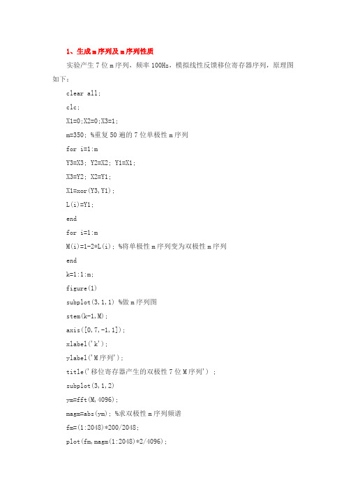
1、生成m序列及m序列性质实验产生7位m序列,频率100Hz,模拟线性反馈移位寄存器序列,原理图如下:clear all;clc;X1=0;X2=0;X3=1;m=350; %重复50遍的7位单极性m序列for i=1:mY3=X3; Y2=X2; Y1=X1;X3=Y2; X2=Y1;X1=xor(Y3,Y1);L(i)=Y1;endfor i=1:mM(i)=1-2*L(i); %将单极性m序列变为双极性m序列endk=1:1:m;figure(1)subplot(3,1,1) %做m序列图stem(k-1,M);axis([0,7,-1,1]);xlabel('k');ylabel('M序列');title('移位寄存器产生的双极性7位M序列') ;subplot(3,1,2)ym=fft(M,4096);magm=abs(ym); %求双极性m序列频谱fm=(1:2048)*200/2048;plot(fm,magm(1:2048)*2/4096);if x_rand(i)>=0.5 %大于等于0.5的取1,小于0.5的取0x(i)=1;a=a+1;else x(i)=0;endendt=0:N-1;figure(2) %做信息码图subplot(2,1,1)stem(t,x);title('扩频前待发送二进制信息序列');tt=0:349;subplot(2,1,2)l=1:7*N;y(l)=0;for i=1:Nk=7*i-6;y(k)=x(i);k=k+1;y(k)=x(i);k=k+1;y(k)=x(i);k=k+1;y(k)=x(i);k=k+1;y(k)=x(i);k =k+1;y(k)=x(i);k=k+1;y(k)=x(i);ends(l)=0;for i=1:350 %扩频后,码率变为100/7*7=100Hzs(i)=xor(L(i),y(i));endtt=0:7*N-1;stem(tt,s);axis([0,350,0,1]);title('扩频后的待发送序列码');N=400000;ybb=fft(s_bpskb,N); %无扩频信号BPSK调制频谱magb=abs(ybb);fbb=(1:N/2)*100000/N;subplot(2,1,1)plot(fbb,magb(1:N/2)*2/N);axis([1700,2300,0,0.8]);title('扩频前调制信号频谱');xlabel('Hz');subplot(2,1,2)yb=fft(s_bpsk,N); %扩频信号BPSK调制频谱mag=abs(yb);fb=(1:N/2)*100000/N;plot(fb,mag(1:N/2)*2/N);axis([1700,2300,0,0.8]);title('扩频后调制信号频谱');xlabel('Hz');title('扩频后经加噪过信道后的信号与原信号时域波形对比'); xlabel('t');axis([0.0675,0.0725,-1.2,1.2]);subplot(2,2,2)ybba=fft(s_bpskba,N); %无扩频调制信号经信道后频谱分析magba=abs(ybba);plot(fbb,magba(1:N/2)*2/N);title('扩频前经信道调制信号频谱');axis([1700,2300,0,0.8]);xlabel('Hz');subplot(2,2,4)yba=fft(s_bpska,N); %扩频调制信号经信道后频谱分析maga=abs(yba);fb=(1:N/2)*100000/N;plot(fb,maga(1:N/2)*2/N);axis([1700,2300,0,0.8]);xlabel('Hz');title('扩频后经信道调制信号频谱');幅,符合高斯白噪声的原理。
MATLAB的扩频通信系统仿真分析研究

基于MATLAB 的扩频通信系统仿真研究摘要本文阐述了扩展频谱通信技术的理论基础和实现方法,利用MATLAB 提供的可视化工具Simulink 建立了扩频通信系统仿真模型,详细讲述了各模块的设计,并指出了仿真建模中要注意的问题。
在给定仿真条件下,运行了仿真程序,得到了预期的仿真结果。
同时,利用建立的仿真系统,研究了扩频增益与输出端信噪比的关系,结果表明,在相同误码率下,增大扩频增益,可以提高系统输出端的信噪比,从而提高通信系统的抗干扰能力。
关键词 扩频通信, 信噪比, 误码率, 扩频增益Simulation of the Spread Spectrum Communication SystemBased on MATLABAbstract: The theory base and realizing methods of the spread spectrum communication technology was presented in this study. The simulation model of the spread spectrum communication system was built by using SIMULINK, which is provided by MATLAB. In addition, each module of the simulation model was introduced in detail ,and pointed out the problems that must be pay attention to in the system simulation. On the basis of the designed simulation conditions, the simulationprogram was run and the anticipant results were gained. Moreover, the relationship between the spread spectrum gain and the fan-out error rate was also studied by use of the simulation system. The results showed that on the base of the same error rate, if the spread spectrum gain was enlarged, the Signal-to-Noise of the system fan-out would be enhanced and the anti-jamming capability of the communication system would also be enhanced. Keywords :spread spectrum communication,Signal-to-Noise, error rate, spread spectrum gain 1 引言扩展频谱通信(简称扩频通信)与光纤通信、卫星通信,一同被誉为进入信息时代的三大高技术通信传输方式,它是指发送的信息被展宽到一个很宽的频带上,在接收端通过相关接收,将信号恢复到信息带宽的一种系统。
扩频通信系统及MATLAB仿真

扩频通信系统及MATLAB仿真
张大亮;黎勇
【期刊名称】《湖北师范学院学报(自然科学版)》
【年(卷),期】2008(028)003
【摘要】先阐述了扩频通信的基本原理、主要性能指标及其工作特点,然后根据香农定理和柯捷尔尼可夫潜在抗干扰理论,借助MatLab工具箱和Monte Carlo仿真算法,建立了直接序列扩频通信系统仿真模型.通过分析无干扰时的误码率仿真曲线与理论计算值,证明了所建仿真模型的正确性.
【总页数】6页(P21-26)
【作者】张大亮;黎勇
【作者单位】湖北师范学院计算机科学与技术学院,湖北,黄石,435000;江铃汽车采购中心,江西,南昌,330001
【正文语种】中文
【中图分类】TN914.42
【相关文献】
1.直接序列扩频通信系统的MATLAB仿真 [J], 赵庆平;李峥
2.直接序列扩频通信系统与MATLAB仿真 [J], 姚玲
3.扩频通信系统及MATLAB仿真 [J], 李江波;索丽敏;尚廷义
4.扩频通信系统分析及信号监测初探 [J], 何小勇;漆骐;韩兵
5.一种优化扩频通信系统帧同步性能的算法 [J], 陈纪平;蔡刚;黄志洪
因版权原因,仅展示原文概要,查看原文内容请购买。
基于MATLAB的扩频通信系统仿真
《通信技术综合实验》实验报告基于MATLAB 的扩频通信系统仿真摘要:扩展频谱通信具有很强的抗干扰性能,其多址能力、保密、抗多径等功能也倍受人们的关注,被广泛地应用于军事通信和民用通信中。
扩频通信系统利用了扩展频谱技术,将信号扩展到很宽的频带上,在接收端对扩频信号进行相关处理即带宽压缩,恢复成窄带信号。
扩频通信技术是一种信息传输方式,其信号所占有的频带宽度远大于所传信息必需的最小带宽;频带的扩展是通过一个独立的码序列来完成,用编码及调制的方法来实现的,与所传信息数据无关;在接收端则用同样的码进行相关同步接收、解扩及恢复所传信息数据。
本文利用MATLAB 对扩频系统中的m 序列的产生、频谱、相关函数,以及整个扩频系统工作原理进行了仿真,为今后扩频通信系统在各个领域的应用和研究提供了依据。
关键词:直扩通信;信噪比;误码率;抗干扰正文:一、实验原理:扩频通信的基本特点是其传输信息所用信号的带宽远大于信息本身的带宽。
除此以外,扩频通信还具有如下特征:1是一种数字传输方式;2带宽的展宽是利用与被传信息无关的函数(扩频函数)对被传信息进行调制实现的;3在接收端使用相同的扩频函数对扩频信号进行相关解调,还原出被传信息。
Shannon 定理指出:在高斯白噪声干扰条件下,通信系统的极限传输速率(或称信道容量)为C = BL og 2 (1 + N S)b / s(2-1)式中:C――为系统的信道容量(bit/s ); B――为系统信道带宽(Hz );S――为信号的平均功率;N――为噪声功率由式中可以看出。
若白噪声的功率谱密度为n0,噪声功率N=nB ,则信道容量C可表示为:1《通信技术综合实验》实验报告C = BLog 2(1+S)b / s n0 B(2-2)由上式可以看出,B、n0、S确定后,信道容量C就确定了。
由Shannon第二定理知,若信源的信息速率小于或等于信道容量C,通过编码,信源的信息能以任意小的差错概率通过信道传输。