霍尼韦尔HONEYWELL手机软件用户使用手册CAWDViewmanual
Honeywell 70 75 Series移动计算机配件指南说明书

Vehicle Dock, CK70/CK71/CK75
871-035-001 (1001AV01)
Vehicle Holder, CK70/ CK71/CK75
805-673-001 (1001AV02)
Retains mobile computer in vehicle environment. Easy one-handed removal of device. Provides USB Host (HDB15M) and RS-232 (DB9M) receptacles. Provides 5V DC on RS-232 Pin 9 for powering peripherals. Requires 805-638-001 Mounting Kit and power option listed below. Optional 850-828-001 Audio Adapter via USB port. Optional USB Host Cable VE0112016. Compatible with Scan Handle or Magnetic Stripe Reader. Not compatible with Snap-On Adapters.
70/75 Series Mobile Computer Accessories Guide |
2
ACCESSORIES GUIDE
PRODUCT NAME Vehicle Dock Mounting Kit
SKU 805-638-001
Power Cable, Dock-to-Fuse Block 226-109-003
Power Option: For connection of Vehicle Dock to forklift power systems operating on 15–96V DC. Provides filtering and conditioning. Includes all power cables and cable mounting hardware.
Honeywell WEBs-N4 软件说明书

Honeywell WEBs-N4 Installation GuideVersion 4.9.0.198September 2020Table of ContentsA BOUT THIS G UIDE (3)D OCUMENTATION (3)S YSTEM R EQUIREMENT FOR WEB STATION-N4 (3)Operating System & Software Dependencies (4)Using Web Launcher with Niagara 4.9 (5)WEB STATION-N4I NSTALLATION P ROCEDURE (6)About this GuideThis document is part of the WEBStation-N4 documentation library. WEBStation-N4 software is distributed via the Honeywell Buildings Forum. The platform requirements needed are mentioned in WEBs N4.9.0.198 Software Release Bulletin.For the latest product data, visit or Honeywell Building Controls.NOTE: This version of Honeywell WEBs-N4.9.0.198 is compatible with Spyder Model 5, CIPer Model 10, and WEB-8000 controllers. CIPer Model 30 and CIPer Model 50 controllers are not compatible with this release. DocumentationEach view/dialog is provided with a Help button. Click the Help button to open a help window, that explains the functionality of the displayed view. Alternatively, each view has a help page which can be opened by pressing the F1 key on the keyboard or navigate to Help tab in menu items and click Help On View.Refer the Honeywell Buildings Forum Documents for all latest WEBs-N4 product related documentation. System Requirement for WEBstation-N4IMPORTANT NOTEN4.9 supports only 64-bit installations. So, installing N4.9 will generate a new host ID, if you made a 32-bit in-stallation in the previous N4.X versions. Be sure to transfer your Niagara Workbench license from your previous32-bit host ID to your new 64-bit host ID.To use Lon devices with station running in Windows, use LON tunneling with JACE or use LON/IP.Operating System & Software DependenciesWEBs-N4 is supported on the following listed Microsoft Windows operating systems. The application installation in-cludes Oracle’s Java Runtime Environ ment (JRE) and does not depend on any other software to run.Using Web Launcher with Niagara 4.9Web Launcher 20.1.3 was recently revamped for N4.9 to include essential software dependencies updates along with critical defect fixes. This version of Web Launcher has Java version 8 update 252 and certificate management has been updated to work with N4.9 along with any legacy or prospective release. Prior to using Web Launcher with N4.9, customer should update Web Launcher accordingly (see steps below).How to update Web Launcher?Web Launcher has a feature to check for updates over the internet and prompts the user when a new version is avail-able in the cloud. However, existing version of Web Launcher has a bug that prevents a smooth update. Users will be required to perform a fresh install by downloading the latest version from the cloud via the station web Login page. Click on the Niagara Web Launcher Installer link on the station's Web Launcher Web Page, which can be reached via the link on the Login page itself. Once the download is successful, click on the msi file and follow the installation wiz-ard. You do not have to uninstall the older version. The new installation will automatically update to the latest version.WEBstation-N4 Installation Procedure1.Double click the executable file (Installer_x64.exe)The WEBStation-N4 Installation Program window opens, showing information such as build version, date etc.Click Next to proceed the installation.2.Click Yes to agree with the End User License Agreement [EULA] and Next to continue the installation.Or Click No to cancel the installation.3.The installer loads C:\Honeywell\WEBStation-N4-4.9.0.198 path by default. If this path does not exist,the installer displays warning message, Click Yes to create the folder. Click Next to continue installation.4.If you do not wish to install the WEBStation-N4 in the default directory, click Browse to change the path,and click Next to continue.NOTE: If you are performing a new installation, the installer prompts you to set a system passphrase for en-cryption purposes, as shown in the following image.The system passphrase is used to protect sensitive information stored on all WEBs systems, and on the SD card in WEB-8000 controllers. The system passphrase i s assigned as the file passphrase for “portable files, such as backups and station copies, and is used to encrypt those files. During operations in which you transfer encrypted files to a system (restoring backups, transferring a station, etc.) you are prompted to sup-ply the file passphrase, if it doesn’t match the system passphrase. The system passphrase defaults to the factory default platform password.During commissioning, you will be prompted to change the default system passphrase.NOTE: It is important to remember the system passphrase and keep it safe. If you lose the system pass-phrase, you will lose access to encrypted data. To change the system passphrase, use the Platform Admin-istration tool.5.Niagara Deamon User Home directory is used to store Niagara Deamon user’s data and to run Niagarastations. By default, the directory is created under C:\ProgramData\Niagara4.9\Webs as shown below.If this path does not exist, the installer displays warning message, requesting to create the folder. Click Yes to continuee the Browse option to change default folder location, if desired.Or Click Next to continue.7.Check the options to install Desktop Shortcuts, if needed. Click Next to run the installation.8.After completing of the installation, the installer displays message “WEBStation-N4 installation iscomplete".9.Check the required options and click Finish to complete the installation process.10.Once the installation is finished, license get installed automatically. Click Continue to run WEBstation-N4.WEBs-N4 Workbench opens as shown below.。
Honeywell C300控制器用户指南说明书

Process SolutionsHoneywell’s C300 controller provides powerful and robust control for the PlantCruise by Experion® platform. With the C300 and the Control Execution Environment,customers can improve engineering productivity and maintenance, maximize process uptime, and reduce production costs.At the core of the C300 in PlantCruiseis Honeywell’s field-proven deterministic Control Execution Environment (CEE) core software. The CEE provides a superior control execution and scheduling environment. Control strategies are configured and loaded through Control Builder, an easy to use and intuitive engineering tool.The C300 controller hardware offers unique space saving, installation, and maintenance benefits consistent with its innovative Series 8 form factor.The C300 is optionally redundant, requiring no additional hardware other than an identical second hardware module.The ‘designed-vertical’ C300 controller provides a superior control execution and scheduling environment.With the C300 controller, customers can:• Improve engineering productivity with a rich set of function libraries and a seamless and intuitive user environment, • Maximize process uptime and minimize maintenance effort with robust diagnostics and full hardware redundancy, and, • Reduce production costs with flexible and efficient control strategies, on-process migration, and efficient hardware processing power.Easy Control Strategy Creation through Rich Function LibrariesThe Control Execution Environment function blockssupport:• Continuous Control • Logic Based Control • Sequential Control • Model Based ControlEach function block contains a rich set of predefined features, such as alarm limits and priorities, various control algorithms, and maintenance statistics, all of which are configurable parameters. Function blocks are linked together in Control Modules to perform specific control tasks, which provide a foundation for efficient control engineering.Embedded functionality guarantees consistent control strategyexecution and delivers consistent alarming and operations behavior. This consistency reduces operator errors and saves implementation time by eliminating the need to develop low-level basic functions.The CEE fully supports the ISA S88.01 batch standard and integrates sequences with devices. The devices will track the state of the sequences and perform pre-configured actions based on those sequences. This reduces the implementation and complexity of handling abnormal situations. The SCMs support abnormal handling, recipe parameters, and on-line monitoring of the execution through chart visualization.One Seamless Environment through Easy Data CommunicationParameters provide access to every imaginable piece of information in the controller. This data can be used throughout the Experion system, whether for other control strategies or for operator purposes. For example, in custom displays, parameters such as setpoints or outputs can be historized and used in trend views. The engineer does not need to know where the information resides. Instead, he can just reference it, and the system manages the underlying logistics of that information. The system will notify the user based on the status information associated with the value and take appropriate action when required.Each parameter is also protected from accidental changes through a security access level, and certain parameters can only be changed off-line. Communication is based on report- by-exception and publish-subscribe, making efficient use of communication bandwidth by accessing data only when needed and avoiding duplication.Consistent and Predictive Behavior Makes Engineering and Maintenance EasierThe C300 CEE supports an execution period per control strategy, ranging from 50 msec to 2000 msec. The user can make changes to existing or add new control strategies without interrupting other control strategies executed by the controller. The user has full control over the function block execution order within the control strategy and the execution order of multiple control strategies. Control strategies can be easily moved between control environments by using the convenient drag-and-drop feature within Control Builder. Easy and Intuitive Engineering EnvironmentControl Builder is the control engineering and maintenance tool for the Control Execution Environment, and improves the control engineer’s productivity by simplifying configuration with a graphical user interface and predefined function blocks ready for wiring into a specific control strategy. The control engineer can enable and change standard function block features without the need to build these from the ground up. The control strategy can be documented with embedded objects such as text, documents or web-links.Online Monitoring Is Available to the Engineer and OperatorOnce control strategies are created and loaded to the C300 controller, the engineer can monitor the strategy on-line using the same graphical interface. This is helpful for verifying a control strategy or for troubleshooting a process problem. The control or maintenance engineer can directly modify parameters from the engineering environment without needing an operator interface. Controller Based Model Predictive Tuning with ProfitLoopProfit Loop is Honeywell’s patented algorithm that provides a single input / single output model-predictive function block that is included in the standard C300 controller function block library. It has the operating simplicity and computational efficiency of a standard PID function block, yet provides tight, robust control, increasing process stability by up to 30 percent. Profit Loop creates a simple model of the process to predict the effect of control moves on the process (controlled) variable. Because Profit Loop can anticipate future process behavior, the controller knows exactly how much to move the process to meet the desired control objectives. Profit Loop incorporates the best elements of both traditional PID algorithms and the model-based control and optimization technologies of Profit Controller at the regulatory level.For More InformationTo learn more about how Honeywell’sPlantCruise by Experion C300 Controller can improve plant performance, visit our website or contact your Honeywell account manager. Honeywell Process Solutions Honeywell1250 West Sam Houston Parkway South Houston, TX 77042Honeywell House, Arlington Business Park Bracknell, Berkshire, England RG12 1EB Shanghai City Centre, 100 Junyi Road Shanghai, China 20051 Custom Algorithm Blocks Custom Algorithm Blocks (CABs) are similar in purpose and structure to native function blocks included with Control Builder. These blocks have predefined algorithms and data structures. By contrast, Custom Algorithm Blocks have user defined algorithms and data structures. CABs are developed using Visual Basic integrated into Control Builder.The C300 controller supports the execution of CABs in Experion LX. CABs can greatly reduce the effort required to create complex control strategies that require the robust control environment offered by the C300.Investment ProtectionHoneywell is committed to protecting customer investments by supporting and integrating previous control products. Consistent with this philosophy, the Control Execution Environment, which holds the user application, is platform- independent. This allows the user to make use of new, more powerful hardware platforms when they become available, while retaining the specific user application.PN-13-16-ENG February 2014© 2014 Honeywell International Inc.。
Honeywell 35 Series Embedded NVR支持说明书

FEATURES AND BENEFITSSupports Honeywell 35 Series Embedded NVRs Connection to NVR anytime anywhere (local,remote, global P2P)Multi-NVR magement, supports up to2048 video channel connectionSupports two way audio through 35S NVR with 35S camerasSupports up to 64 live view windows in 1 single screenSupports Windows® 10 (64-bit)Auto streaming size to save decode and streaming bandwidthSupports receiving video analytic events from 35S series cameras through 35S NVRDual monitorsconfigurable to display live view, tour, E-map or event viewsEditable displayinformation on liveview End to end HTTPs stream encryptionVideo recording and playback managementEvent management and event trigger Device management PTZ ControlMFZ and digital zoom Fisheye dewarping E-mapHONEYWELL SMARTVIEWERHoneywell Smart Viewer (HSV) is designed to connect and manage multiple 35 Series Embedded NVRs.For 35 Series NVRsFeaturing a user-friendly interface, HSV can be deployed for device management and configuration, video live view and playback, event management, PTZ control, fisheye camera de-warping and E-map.This view also features multiple monitor support, multiple display layouts, customized views and tours, two-way audio and global P2P remote connection for efficiency monitoring and operation. HSV supports up to 2048 cameras and multiple NVRs making it ideal for medium to large scale video surveillance systems. With HTTPS and TLS 1.2 encryption streaming and communication between HSV and 35 Series NVRs, customers can increase compliance, reduce potential liability costs and realize the benefits of an end-to-end encrypted and secure video surveillance.MARKET OPPORTUNITIESIntuitive user interface, full features, HTTPs encryption, multiple sites management, global P2P enabled remote connection make this video management viewer perfect for a wide range of medium and large scale security applications where efficiency is important, compliance is essential and data is protected.SYSTEM DIAGRAM35 Series NVRs InternetHoneywell Smart ViewerIP Cameras * For more hardware and integration details, please refer to user manualTECHNICAL SPECIFICATIONSComputer version available onhttps://Android™ is a trademark or registered trademark of Google Inc. in the United States and/or other countries.Apple® is a trademark or registered trademark of Apple, Inc. in the United States and/or other countries.Intel® and Core™ are trademarks or registered trademarks of Intel Corporation or its subsidiaries in the United States and/or other countries.Microsoft® and Windows®are either registered trademarks or trademarks of Microsoft Corporation in the United States and/or other countries.ONVIF and the ONVIF logo are trademarks of ONVIF Inc.HEVC Advance logo is a trademark of HEVC Advance .Honeywell reserves the right, without notification, to make changes in product design or specifications.HVS-35HSV-02-US(0123)DS-Y© 2023 Honeywell International Inc.For more information:/securityHoneywell Commercial Security 715 Peachtree St. NE Atlanta, GA 。
Honeywell Alerview 7英寸手机式数字平板说明书
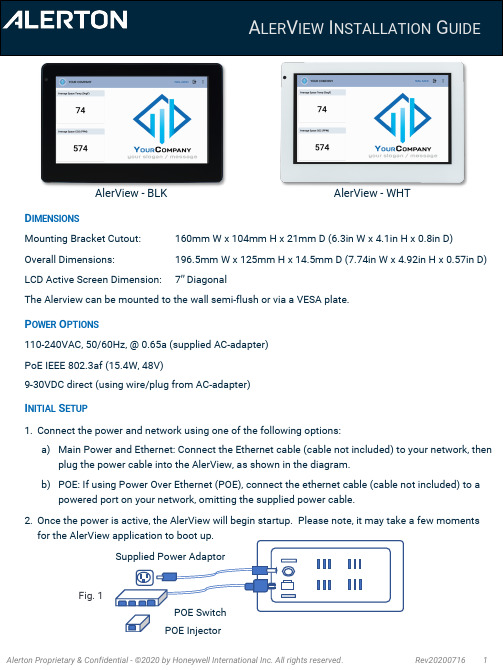
AlerView -WHTAlerView -BLKD IMENSIONSMounting Bracket Cutout: 160mm W x 104mm H x 21mm D (6.3in W x 4.1in H x 0.8in D)Overall Dimensions:196.5mm W x 125mm H x 14.5mm D (7.74in W x 4.92in H x 0.57in D)LCD Active Screen Dimension:7” DiagonalThe Alerview can be mounted to the wall semi-flush or via a VESA plate.P OWER O PTIONS110-240VAC, 50/60Hz, @ 0.65a (supplied AC-adapter)PoE IEEE 802.3af (15.4W, 48V)9-30VDC direct (using wire/plug from AC-adapter)I NITIAL S ETUP1.Connect the power and network using one of the following options:a)Main Power and Ethernet: Connect the Ethernet cable (cable not included) to your network, thenplug the power cable into the AlerView, as shown in the diagram.b)POE: If using Power Over Ethernet (POE), connect the ethernet cable (cable not included) to apowered port on your network, omitting the supplied power cable.2.Once the power is active, the AlerView will begin startup. Please note, it may take a few moments for the AlerView application to boot up.A LER V IEW I NSTALLATION G UIDEFig. 1POE Switch POE InjectorSupplied Power AdaptorI N -W ALL M OUNTING1.Make the cut out for the AlerView: Make a cutout in the wall160mm W x 104mm H x 21mm D (6.3in W x 4.1in H x 0.8in D); or use the in-wall bracket as a template.2.Install the mounting bracket into the cutout: Insert the mountingbracket into the wall cutout with the flanges at the bottom. Use 4 screws (not supplied) to fix the bracket to the wall.3.The bracket can also be used for surface mounting using the75mm x 75mm VESA holesI NSTALLING THE A LER V IEW :1.Insert the Ethernet cable (marked "A" in Figure 3) into the RJ-45 connector (LAN /POE) on theAlerView (marked "A" in Figure 4). Insert the power cable at this point if not using POE.2.Align the tabs on the mounting bracket (marked "B" in Figure 3) with the slots on the AlerView(marked "B" in Figure 4). Attach the AlerView to the mounting bracket by inserting the tabs on the bracket into the mating slots on the AlerView and then gently pushing downward to lock into place.3.Secure the AlerView to the mounting bracket flanges using the provided screws in the base.FCC N OTICE : This device complies with Part 15 of the FCC Rules. Operation is subject to the following two conditions: 1) Thisdevice may not cause harmful interference. 2) This device must accept any interference received, including interference that may cause undesired operation.NOTE 1: This equipment has been tested and found to comply with the limits for a Class B digital device, pursuant to part 15of the FCC Rules. These limits are designed to provide reasonable protection against harmful interference in a residential installation. This equipment generates, uses and can radiate radio frequency energy and, if not installed and used inaccordance with the instructions, may cause harmful interference to radio communications. However, there is no guarantee that interference will not occur in a particular installation. If this equipment does cause harmful interference to radio ortelevision reception, which can be determined by turning the equipment off and on, the user is encouraged to try to correct the interference by one or more of the following measures:•Reorient or relocate the receiving antenna.•Increase the separation between the equipment and receiver.•Connect the equipment into an outlet on a circuit different from that to which the receiver is connected.•Consult the dealer or an experienced radio/TV technician for help.NOTE 2: Any changes or modifications to this unit not expressly approved by the party responsible for compliance could void the user's authority to operate the equipment.Fig. 3Fig. 2Fig. 4A LER V IEW I NSTALLATION G UIDE(CONTINUED )++++++++++++++++++++++++++BBAB++++++++++++++++++++++++B B A。
Honeywell HRXD DVR用户指南说明书
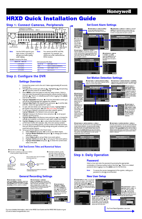
HRXD Quick Installation GuideFor Front Panel Operation, see over.For more detailed information, refer to the HRXD User Guide and the HRXD RAS Guide on your CD and at .Throughout the screens you will see . Highlighting and pressingwill reset the screen to its default settings.General Recording Settingsis checked to program the DVR to record based on time, day of the week, and holidays. Select + to # Record Menu ➤ Set Event Alarm SettingsSet Motion Detection SettingsStep 3: Daily OperationPasswordSelect a User and enter the password by pressing the appropriatepassword when logging in as the admin user for the first time.NoteTo assure the secure management of the system, setting up a password is strongly recommended.New User Setup! Event Menu ➤ Alarm-In Settings .Set up each alarm input from theterminal strip on the back of the DVR." Activate eachinput being used and give it a Title. Set each input as either normally open (NO ) or normally closed (NC ).# Event Menu ➤ Alarm-In ➤ Actions 1.Highlight Actions 1 to open the Actions 1 setup screen. Set the actions the DVR will take when it senses an input in the Alarm-Out column. Also select which cameras the DVR should record when an alarm is present.$ Event Menu ➤ Alarm-In➤ Actions 1 ➤ Notify .Select the Notify field for an alarm input to set who will be notified when the alarm is detected.% Event Menu ➤ Alarm-In ➤ Actions 2. HighlightActions 2 to open the Actions 2 setup screen. On this screen, select the PTZ presets to run and spot monitors to display when an alarm is present.➤ Sensitivity . # Event Menu ➤Motion Detection ➤ Min. Blocks . Adjust the minimum number of detection blocks for Daytime or Nighttime independently. Smaller numbers of Minimum Blocks provide greater sensitivity.$ Event Menu ➤Motion Detection ➤ Zone screen . You can define the area of the image where you want to detect motion (a doorway, for example).Zone screen is laid camera. Set up the zones by selecting %Event Menu ➤Motion Detection ➤ Zone Screen ➤ Zone Menu . Select a motion zone block and press Select ) or Clear ) & Event Menu ➤ Motion Detection ➤ Actions 1.From this screen, the DVR can be set to react differently to each motion detection. You can associate multiple cameras with the motion detecting camera, recording video from all the associated cameras when motion is detected. In the Alarm-Out field you can select which alarm outputs will be triggered when motion is detected. You can also select which devices or users will be notified when motion is detected.' Event Menu ➤ Motion Detection ➤ Actions 2. From this screen, the DVR can be set to react differently to each motion detection. You can select a PTZ preset position for each PTZ camera to move to when motion is detected. In the Spot Monitor field you can associate a different camera with each spot monitor, so that specific cameras will be displayed on the spot monitors when motion is detected.! System Menu ➤ User users and user groups, select System menu. Delete Users or Groups by selecting the corresponding andpressing . Highlight a User Name and assigned to that User. You can also change the User’s group."New User the User setup screen and press keyboard to enter the new User Name. Assign the User to a Group and enter a password with the camera buttons.System Menu ➤ User ➤ New. Select + Group... on the User setup screen and press . Use the virtual keyboard to enter the new Group Name. Assign the Authority level for the group by selecting the appropriate Authority boxes.HRXD Quick Installation Guide+TV (North America only)************************Specifications subject to change without notice.Imperial conversions are approximate.© 2007 Honeywell International Inc.Document 800-00280 – Rev A – 05/07to open the Search menu. Pick a search method to find an incident with:Date and Time Search1.Move the cursor over the date/time and press2.Move Left or Right to highlight the date/time value to change.e the Up and Down buttons to change the date/time value to the date/time that you want to search through.4.Once you have set the date and time you want, press5.Highlight6.The selected time and date will display. If no video was recorded in that time, a7.Use the playback controls to search through the video.Calendar SearchEvent Log SearchMotion SearchCopy Evidence to a CDClip-Copy ScreenReviewing Video ClipsYou do not need to install any special software on your personal computer to review the video clips. The copied video clips contain the Clip Player program.1.If you used a USB storage device, disconnect it from the DVR andconnect it to your PC. If you used a recordable CD, insert the CD into your computer’s CD drive.2.The Clip Player screen displays the clip images. Use the Clip Playercontrols to view the video.1.Days with recorded video display in white.2.3. A time bar displays at the bottom of the calendar. Hours with video recorded are highlighted orange.4.Select the time bar and select the time to search.5.If there is more than one video stream in the same time range, move to Select a Segment and select the video stream you want to search.6.Highlight Go 7.The selected time and date will display. Use the playback controls to search through the video.1.The DVR maintains a log of each time an Event occurs. The Event Log Search screen displays this list.2.Highlight the event that you want to view.3.image of the event.4.Press Search to return to live monitoring.5.You can narrow your event search by selecting Option... and setting up a new search condition. See the User Guide for more information.1.The Motion Search screen allows you to search for motion activity that occurred within the area of a configurable zone of interest.e the arrow buttons to highlight the event for which you want to view video and press3.The first image of the associated event video displays in the small search screen in the left pane of the screen.4.To view and play back the video in full screen, highlight Close5.You can narrow your event search by selecting Option... and setting up a new search condition. See the User Guide for more information.The Clip-Copy screen can be used to copy video clips to an internal CD-RW, or external USB drive.1.In Search mode, press and hold MENU for 2seconds to open the Clip-Copy screen.2.The Data Source (Record or Archive) isdisplayed.3.Set the start and stop times and dates.4.Select the cameras to include in your video clip.5.If necessary, enter a password that will have tobe entered when reviewing the video clips.6.In the box beside Dest., select the storagedevice you would like to record the video clip onto.7.Change the default File name , if necessary.8.Select Start Exits the Player programGo forward one framePlay the video clipGo back one framePlay in fast reverseGo to the beginning of the clipPlay in fast forwardGo to the end of the clipShow the previous pageCycle through screen layoutsShow the next pageSelect from Save, Print, Info, Image Processing and Video FormatSelect from Normal and Double screen viewsDisplay image full screen。
Honeywell 传感器和开关应用说明书

Sensors and Switches for Valves and Flow Meters An Application NoteBackgroundFlow meters can measure and regulate volumetric flow, velocity from which the volumetric flow is determined, and mass flow. Valves control or regulate the flow of gases or fluids by partially obstructing, opening or closing the pipeline that carries the media. In many applications, they are operated manually by a lever, pedal, or wheel. Valves are often used in oil and gas, chemical manufacturing, water reticulation and mining applications. Automatic valves with diaphragms or pistons are often actuated by changes in pressure, temperature or flow.SolutionsHoneywell manufactures a wide range of sensors and switches, from simple on/off switches to electronic sensors designed to deliver system control, fluid level indication, temperature regulation, along with protection from overheating and starting/stopping the compressor. Honeywell components provide enhanced reliability, minimize down time, and improve robustness in most harsh environments.Various package options are available, including stainless steel, and those designed for hazardous and harsh-duty applications.Hazardous-location limit switches – These specialized switches perform a number of functions, including monitoring the position ofthe valve stem, actuator or wheel position, providing on-off position on manual process valves, providing real-time valve status information for improved productivity and safety. As these limit switches are enclosedin an explosion-proof housing, any flame path is extinguished inside which mitigates the risk of causing an explosion at the switch part.These switch components provide feedback for the user to take actionin order to prevent explosions in hazardous environments. Hazardous-location switches are employed in valves in outdoor, above-ground, potentially explosive environments such as oil and gas or water treatment applications.Limit Switches – Employed to monitor the position of the valve stemor actuator, limit switches are primarily used on valves in non-explosive environments such as waste water treatment plants, power generation plant or other factory applications. They also allows users to remotely monitor the valve stem, actuator lever, or wheel position for improved productivity and reduced total installed cost in hazardous locations.Figure 1. Industrial Valve ApplicationValves serve a variety of purposes in industrial applications, although their main purpose is to control media through a system.Wireless Limit Switches – Allows users to remotely monitor valve stem, actuator lever, or wheel position for improved productivity and safety, while reducing total installed cost with an economical wireless point-to-point solution.Basic Switches –Snap-action switches monitor the position of the valve handle by indicatingif the switch is actuated. These switches are employed on valves used in both non-explosive environments such as waste water treatment plants and/or other factory applications and also explosive/hazardous applications. Invalve monitoring applications, basic switches perform position sensing on cams with no power consumption. In addition to valves, Honeywell’s V15W2 Series is suitable for use in hazardous environments such as refrigeration, HVAC,appliances, and paint booths.Hall-effect Speed Sensors and Sensor ICs – In flow meter applications Honeywell’s speed sensors measure flow by monitoring revolutions of the impeller (an inside propeller). Eachrevolution of the impeller equates to the delivery of a certain amount of fluid. For example, if the user sets a fluid level of five gallons per minute,the speed sensor counts the impeller rotation so that the correct amount of fluid is delivered. Invalve monitoring application, Hall-effect sensor ICS measure position sensing on cams.Position Sensors – In flow meter applications, Hall-effect magnetic position sensors are usedto determine valve position. In valve monitors, position sensors deliver continuous position status with enhanced reliability and accuracy.Pressure Transducers and Switches – In valve actuator applications, pressure transducers and switches measure the pressure of the diaphragm to help regulate and control the flow within the pipeline. The sensors can measure differential pressure by comparing values across the valve. They can also give an indication of valve position related to opening and closing by measuring the pressure value at that time.Snap-Action SwitchPosition SensorSMART Position SensorHall-Effect Position Sensor ICwith Actuatorsin hazardous locationsLimit SwitchLearn more aboutthe XYR6000OneWireless™ SensorClick here to view Hazardous Area Limit SwitchesRead more about MICRO SWITCH Limit Switches12Explosion-Proof Valve Position IndicatorMICRO SWITCH VPX • Valve position indicator in explosion-proof housing2334Basic SwitchMICRO SWITCH BZ, V7, V15, V15W2, and ZW Series • Large, miniature, and subminiature basic switchesHazardous Location Limit SwitchMICRO SWITCH LSX, CX, and BX Series • Premium limit switches in explosion-proof housingLimit SwitchMICRO SWITCH HDLS, GL, and Double Break Series • Premium heavy duty and standard global limit switches14Figure 4. Switches in Valve Actuators and PositionersClick here to view VPX Series Valve Position IndicatorsGet details on the SMART PositionSensor familyFigure 5. Sensing and Switching Products Used in Valve ActuatorsHazardous Location Position Sensor XYR6000 OneWireless™ SeriesAllows users to remotely monitor valve stem, actuator lever, or wheel position for improved productivity and safety, while reducing total installed cost in hazardous locations; part of a scalable ISA100 mesh networkHazardous Area Limit SwitchMICRO SWITCH™ LSX/CX/BX/EX SeriesMonitors valve stem, actuator lever, or wheel position, providing real-time position status for improved productivity and safety in hazardous locationsLimit SwitchMICRO SWITCH™ HDLS, GLS, and Double Break SeriesMonitors valve stem, actuator lever, or wheel position, providing real-time position status for improved productivity and safetyPosition SensorSMART Position Sensor, SPS Series 75 mm Linear Monitors valve stem or actuator position1234Stainless Steel Media Isolated Pressure Sensor or Pressure Switch MLH, PX2, or PX3 Series Pressure Sensor or HP, HE, ME, LP, or LE Series Pressure SwitchMeasures diaphragm pressure6Valve Actuator(Kammer valve actuator photoused with permission of Flowserve.)Wireless Limit SwitchMICRO SWITCH™ HDLS and GLS SeriesAllows users to remotely monitor valve stem, actuator lever, or wheel position for improved productivity and safety, while reducing total installed cost with an economical wireless point-to-point solution5Learn more about MICRO SWITCH Basic SwitchesReview Limitless™ Wireless SwitchesFind out more on Hall-effect Speed SensorsFigure 6. Sensing and Switching Products Used in Valves and Flow MetersSMART Position Sensor SPS Series75mm analog and 225 mm analog and digital linear configuration Position Sensor SR SeriesDigital position sensorHall-Effect Sensor LCZ or 3000 SeriesSingle, zero speed sensor (LCZ) or high resolution VRS sensor (3000)Basic SwitchMICRO SWITCH BZ, V7, V15, V15W2, and ZW SeriesLarge, miniature, and subminiature basic switchesHazardous Location Limit Switch MICRO SWITCH VPX, CX, LSX, and BX SeriesPremium limit switches in explosion-proof housingLimit SwitchMICRO SWITCH HDLS, GLS,and Double Break SeriesPremium heavy duty and standard global limit switchesFlow MeterClick here to view Pressure TransducersMore information available here on Hall-effect Sensor ICsTypes of ValvesSpecifically, there are several main types of valves: 1) Manual process valves, 2) Valve actuators/positioners, 3) Valve monitors/indicators, 4) Valves and flowmeters, and 5) Sanitary and food/beverage valves.Manual Process Valves – Manual process valves in industrial facilities control the flow of liquid, gas, slurry, or steam. Eighty percent require operators to manually open, close, or otherwise control the valve. At any given time, users may not know the actual position of the valve. Process plants, including refineries, chemical, pharmaceutical, and water treatment plants as well as power generation installations, all need a better way to verify status with or without human intervention, especially in hazardous or hard-to-reach locations. (See Figures 2 and 3)Valve Actuators/Positioners – A valve actuator is a pneumatic or electric mechanism used in process control systems to automatically open or close valves. Actuators can be used with either linear or rotary valves in industrial, medical, food/beverage, and transportation applications. In standard valves, when the valveis given a command to open to a certain point, there is no feedback to verify that it has opened to that position. Valve positioners utilize a source of power to operate and continuously adjust a valve. The power source can be a manual gearbox or an electronic device with control and measuring devices; Available with hydraulic, pneumatic, and electric operating mechanics, these are often used in pipelines, process plants and in remote areas. Postioners can be used for opening or closing a valve to control the rate of fluid flow based on a signal from a central control system. With a valve positioner, the command is given and the valve positioner reads the opening, verifies position, and readjusts (if necessary) to the exact position needed which allows for excellent precision in the valve setting. (See Figures 4 and 5)Valve Monitors/Indicators – Mechanical or electrical valve monitors and indicators are used in process control to show valve position. They provide an electrical signal, and sometimes visual feedback, to accurately monitor and verify that a valve is in the correct position. Valve monitors are mostly used in conjunction with a valve positioner/actuator to provide information from remote locations that are not easilyaccessed, or where power isn’t readily available. Potential applications include chemical, pharmaceutical, power generation and oil and gas processes. (See Figures 4 and 5)Valves and Flowmeters – Valves control or regulate the flow of gasses or fluids by partially obstructing, opening or closing the pipeline that carries the media. Valves are often usedin oil and gas, chemical manufacturing, water reticulation and mining applications. In many of these applications, the valves are operated manually by a lever, pedal or wheel. Automatic valves with diaphragms or pistons are often actuated by changes in pressure, temperature or flow.Flow meters can measure and regulate volumetric flow, velocity from which the volumetric flow is determined, and mass flow. The turbine flow meter translates the mechanical action of the turbine rotating in the liquid flow around an axis into a user-readable rate of flow (gpm, lpm, etc.). The turbine wheel is set in the path of a fluid stream. The flowing fluid impinges on the turbine blades, imparting a force to the blade surface and setting the rotor in motion. Nearly all flow meters mustbe installed so that there is a significant runof straight pipe before and after the locationof the flow meter. This is intended to allow the straight pipe run to “smooth out” any turbulence produced by the presence of valves, chemical injectors and diffusers, and changes in pipe direction. (See Figure 5)Sanitary and Food/Beverage Valves – Sanitary and food and beverage valves are engineered for pressure control in sanitary (or “clean”) environments. They are usually manufactured with stainless steel for sanitary and high-purity applications. These valves are often constructed as a ball valve around a fullbore design that ensures the product passes through the valve with no restrictions on the flow with minimal pressure drop.Sanitary and food and beverage valves are often found in pharmaceutical, biotechnology, food and beverage, cosmetics, chemical and other industries where sanitary process control is required for steam, gases, and liquids such as water-for-injection systems.000697-7-EN | 7 | 04/21© 2021 Honeywell International Inc.Honeywell Advanced Sensing Technologies830 East Arapaho Road Richardson, TX 75081 /astFor more informationHoneywell Advanced Sensing Technol-ogies services its customers through a worldwide network of sales offices and distributors. For application assistance, current specifications, pricing or the nearest Authorized Distributor, visit /ast or call:Asia Pacific +65 6355-2828Europe +44 (0) 1698 481481USA/Canada+1-800-537-6945Warranty/RemedyHoneywell warrants goods of its manufacture as being free of defective materials and faulty workmanship during the applicable warranty period. Honeywell’s standard product warranty applies unless agreed to otherwise by Honeywell in writing; please refer to your order acknowledgment orconsult your local sales office for specific warranty details. If warranted goods are returned to Honeywell during the peri-od of coverage, Honeywell will repair or replace, at its option, without charge those items that Honeywell, in its sole dis-cretion, finds defective. The foregoing is buyer’s sole rem-edy and is in lieu of all other warranties, expressed or implied, including those of merchantability and fitness for a particular purpose. In no event shall Honeywell be liable for consequential, special, or indirect damages.While Honeywell may provide application assistance per-sonally, through our literature and the Honeywell web site, it is buyer’s sole responsibility to determine the suitability of the product in the application.Specifications may change without notice. The information we supply is believed to be accurate and reliable as of this writing. However, Honeywell assumes no responsibility for its use.m WARNINGPERSONAL INJURYDO NOT USE these products as safety or emergency stop devices or in any other application where failure of the product could result in personal injury.Failure to comply with these instructions could result in death or serious injury.m WARNINGMISUSE OF DOCUMENTATION• The information presented in this product sheet is for reference only. Do not use this document as a product installation guide.•Complete installation, operation, and maintenance information is provided in the instructions supplied with each product.Failure to comply with these instructions could result in death or serious injury.。
霍尼韦尔视频监控 简易操作手册
播放历史视频
按照如下两种方式中的一种播放历史视频:
右键点击历史视频查询结果中的一条记录并选择“播放”或者直接双击该条记
录。
选中查找到的历史视频,拖拽到一个视频播放窗口。
可在历史视频窗口进行相关播放窗口操作以及时间轴操作。
历史视频播放窗口操作
在历史视频播放窗口,使用右键菜单可拍摄快照、全屏显示和停止视频,如下图所
视频监控系统使用手册
1客户端
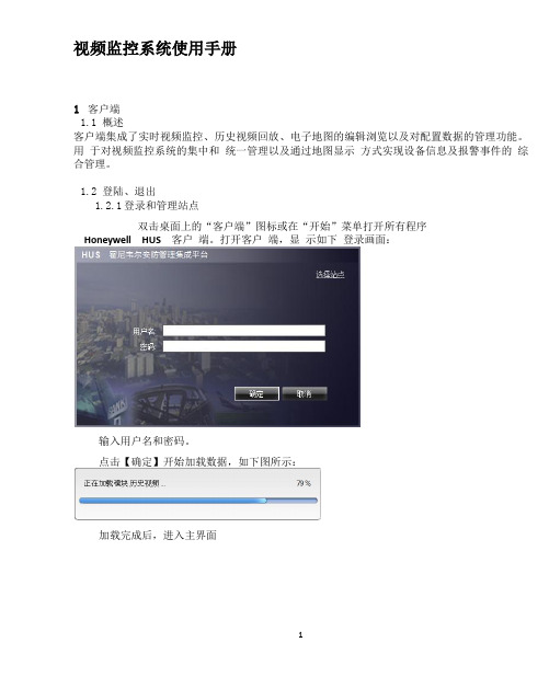
1.1概述
客户端集成了实时视频监控、历史视频回放、电子地图的编辑浏览以及对配置数据的管理功能。用于对视频监控系统的集中和统一管理以及通过地图显示方式实现设备信息及报警事件的综合管理。
1.2登陆、退出
1.2.1登录和管理站点
双击桌面上的“客户端”图标或在“开始”菜单打开所有程序
1.8视频轮巡使用和设置说明
巡更
点击 进入配置巡更界面:
配置巡更
巡更配置
在“巡更”框下展开“本地巡更”和“大屏巡更”,查看全部巡更,
选择一个巡更,在“已选场景”框中显示该巡更所配置的场景,选择某一场景点击
下方的【新建】,弹出如下窗口,显示该场景的设置信息,包括窗口布局以及每个窗口的视频设备:
巡更场景配置
按下 键进入回放模式,此时大屏上选中的框就会变成黄色。
按下 用来切换NVR模式。
按下 键开启回放时间条,通过旋转摇杆来控制时间条的精度,通过移动摇杆,选择要回放的时间段。按键盘上的 键开始播放历史视频
用 按键来控制播放的速度。
按 键停止播放视到当前时间
按键盘上 键,进行倒放,也可以用 按键来控制播放速度
1.5.1选择“工具栏”最上面的图标 选择“大屏”切换到大屏播放。
- 1、下载文档前请自行甄别文档内容的完整性,平台不提供额外的编辑、内容补充、找答案等附加服务。
- 2、"仅部分预览"的文档,不可在线预览部分如存在完整性等问题,可反馈申请退款(可完整预览的文档不适用该条件!)。
- 3、如文档侵犯您的权益,请联系客服反馈,我们会尽快为您处理(人工客服工作时间:9:00-18:30)。
镜头
目录
设备
9
弹出添加目录、设备、镜头菜单选项 搜索本地镜头
修改连接参数
点击 图标,选择”修改连接参数”选项,进入“修改设备”对话框:
A)点击 图标,返回设备管理列表; B)点击 图标,保存当前配置;
修改名称
点击 对话框:
图标,选择”修改名称”选项,弹出“修改名称”或者“修改目录”
10
A)点击“确定”按钮,保存当前配置; B)点击“取消”按钮,取消修改
此功能!
找回密码
在登录界面中,点击“找回密码”按钮,跳转至“找回密码”界面:
22
输入用户名,点击“找回密码”按钮,如果所输入的用户名存在,并且用户 在注册时输入了邮箱地址,则会发送密码信息至邮箱地址。
如果忘记了邮箱地址,在输入用户名后,可以点击“找回邮箱”按钮,查看 邮箱地址。
2.2 实时预览
主菜单中,点击“实时预览”,进入实时预览界面后,再点击“收藏”图标, 可以跳转至“收藏夹”界面:
26
图标说明: 图标
返回主菜单
功能说明
点击弹出修改参数、名称等菜单选项
镜头
目录
27
设备 弹出添加目录、设备、镜头菜单选项 搜索本地镜头
修改连接参数
点击 图标,选择“修改连接参数”选项,进入“修改设备”对话框:
28
A)点击 图标,返回设备管理列表; B)点击 图标,保存当前配置;
修改名称
删除
点击 图标,选择”删除”选项,直接删除当前设备(目录或者镜头)。
添加目录
点击 图标,选择”添加目录”选项,弹出“添加目录”对话框:
A)点击“确定”按钮,保存当前配置,设备管理列表中显示当前添加的目录; B)点击“取消”按钮,取消目录添加
添加设备
11
点击 图标,选择”添加设备”选项:
图标说明: 图标
2
该云服务平台为互联网时代最佳的手机视频监控解决方案,由前端采集设 备、平台服务器和远程观看端三部分构成
1、Android 系统
1.1登陆注册
用户登陆 打开软件,进入登录界面,输入用户名与密码,点击“登录”,即可登录软 件。
图标说明: 图标
功能说明
3
勾选后,再次登录将直接进入主菜单
注:点击“免登录”按钮,不用验证用户名与密码,直接进入系统。 登陆之前可以查看新手向导
用户注册
在登录菜单中,点击“注册”按钮,跳转至注册界面:
输入注册信息,点击“注册”按钮,即可完成注册。 注:请输入正确的邮箱地址,以便忘记密码时找回密码。无帐号登录版本,无此 功能!
找回密码
在登录界面中,点击“登录”按钮,跳转至“找回密码”界面:
4
输入用户名,点击“找回密码”按钮,如果所输入的用户名存在,并且用户 在注时输入了邮箱地址,则会发送找回密码信息至邮箱地址。
23
在“实时预览”中任意选择一项设备,进入了视频预览界面:
24
按钮说明: 图标 返回主菜单 向左移动 向右移动 向下移动 向上移动
功能说明
25
放大 缩小 拉远 拉近 光圈放大 光圈缩小 开启/关闭对讲 开启/关闭扬声器 暂停/播放 抓拍 开启/关闭本地录像 收藏 通道切换
2.3 设备管理
主菜单中,点击“设备管理”选项,进入“设备管理”界面:
主菜单中,点击”本地回放“选项,进入如下界面:
点击 图标,本地回放视频列表变成编辑状态:
18
勾选要删除的视频选项,然后点击 图标,就可以删除选择的本地视频。
1.7 图像浏览
主菜单中,点击”图像浏览“选项,进入如下界面:
点击 图标,本地图像列表变成编辑状态:
勾选要删除的图像选项,然后点击 图标,就可以删除选择的本地图像。
2.1 登录界面
打开软件,进入登录界面,输入用户名与密码,点击“登录”,即可登录软 件。
图标说明: 图标
功能说明
勾选后,再次登录将直接进入主菜单
21
注:点击“免账号登录”按钮,无需用户名与密码,直接进入系统。 登陆之前可以查看使用 向导
用户注册
在登录菜单中,点击“注册”按钮,跳转至注册界面:
输入注册信息,点击“注册”按钮,即可完成注册。 注:请输入正确的邮箱地址,以便忘记密码时找回密码;免账号登陆版本,无
2、IOS 系统.............................................................................. 21
2.1 用户注册登陆...............................................................................................22 2.2 实时预览.......................................................................................................23 2.3 设备管理.......................................................................................................25 2.4 录像回放.......................................................................................................31 2.5 报警管理.......................................................................................................31 2.6 本地回放.......................................................................................................35 2.7 画面预览.......................................................................................................36 2.8 修改密码.......................................................................................................37 2.9 本地配置.......................................................................................................37
介绍
CAWDView
用户使用手册
目录 1.ANDROID 系统....................................................................... 2
1.1 用户注册登陆................................................................................................ 4 1.2 实时预览........................................................................................................ 6 1.3 设备管理........................................................................................................ 8 1.4 录像回放......................................................................................................14 1.5 报警管理......................................................................................................14 1.6 本地回放......................................................................................................18 1.7 画面预览......................................................................................................18 1.8 修改密码......................................................................................................19 1.9 本地配置......................................................................................................19
16
在通知面板中,点击”短信通知“选项,进入”短信通知“面板:
图标说明: 图标
返回报警管理
功能说明
添加短信通知的号码
记录
删除当前添加的号码
点击 图标,选择“记录”选项,弹出”报警记录“对话框:
17
图标说明: 图标 返回报警管理 搜索报警记录 向上翻页 向下翻页
删除所有报警记录
功能说明