霍尼韦尔(Honeywell)液位开关说明书
霍尼韦尔_电动阀门使用说明书

100
0
0
100
141 233
322 (
接线图
尺寸 Fig. 2. ML7420A (mm)
ML7420A (0/2...10 V)
位置反馈
Y
2…10V 0(2)…10V
M
24V 24V~ 1
24V
超越开关
24V~
!
2
附件
12 3456
S1
S2
辅助开关 250 Vac / 5(3) A
4
执行器不会再自动进行自适应模式。
ECC-CDA-VA05-MAR-2011-V01-CN
2
模1信 当)。拟对号输应当入L输对E信应D入灯号LE暗YD可时灯通,亮过输时位入,于型输P号入C为型B2右号..侧.为10按0.V.钮.d1cW0。V2进dc行(出选厂择设(见置图); 注节意。: 按钮W3和W2以及电位计W1可在移开上盖后进行调
技术参数
产品概述
出M暖L2通7..4空.120调0AV系系d统c列的。电位动置阀反门馈执信行号器. 它可们为可阀广门泛提应供用调于节加型热控,制通并风且及输
温度
工作环境温度 贮工存作环介境质温温度度
信号
输入信号 位置反馈信号
安全
电气保护等级 防防护火等等级级
材料
上盖 基座 支架
℃( -10~+50 5~95% RH)
使用说明
器内达M概L与置到7述4阀的特2门弹定0系阀簧的列杆组阀执件杆,行使推实器执力现由行时阀同器门,步的的内电输上部机出下开驱力运关动限动关,制闭。通在。过出一厂个设卡置子范连围接内执。行当 非按针手手 以弹下旋动手动簧旋转旋动复钮钮开,操位并自关执作执顺动执行行时解行器器针锁器连旋接(。。M转件只L7向,有42上执在0运行关A)动器闭带连电。有接源如手件后果动向才执旋下可行钮运以器,动进返在行回;失手自反电动动之情操控,况作制逆下则时。可 所时超 制有,。越的执执行选行器项器会都运带行有到超全越开功或能全关(见的接位线置图,)。不当再超受越输功入能信作号用的控
霍尼韦尔C6097A,B压力开关说明书

PRODUCT DATA65-0237-1CP-UM-5109E® U.S. Registered TrademarkCopyright © 2000 Honeywell Inc. • All Rights ReservedC6097A,BPressure SwitchesAPPLICATIONThe C6097 Pressure Switches are safety devices used in positive-pressure or differential-pressure systems to sense gas or air pressure changes.FEATURES•For use with natural gas, liquid propane (LP) gas, or air.•Diaphragm-actuated safety-limit switch.•Switch can be wired to turn on alarm.•C6097A models break control circuit at setpoint on pressure fall.•C6097B models break control circuit at setpoint on pressure rise.•Lockout with manual reset and recycle options.•Lockout models have external manual reset button.•Removable transparent cover protects scaleplate and adjusting knob.•Pipe tappings allow selection of positive pressure, differential pressure (air only) or venting connections (NPT mount only).•1/4 in. NPT or flange mount models for direct mounting to Honeywell Integrated Valve Train.•Optional switch position indicator lamp available.•IP54 enclosure standard.•Ranges: 0.4 to 5 in. wc, 3 to 21 in. wc, 12 to 60 in. wc or 1.5 to 7 psi.•Surge orifice.ContentsApplication ........................................................................1Features ...........................................................................1Specifications ...................................................................2Ordering Information ........................................................2Installation ........................................................................4Wiring ...............................................................................5Settings and Adjustments .................................................5Operation and Checkout ..................................................6C6097A,B PRESSURE SWITCHES65-0237—12ORDERING INFORMATIONWhen purchasing replacement and modernization products from your TRADELINE® wholesaler or distributor, refer to theTRADELINE® Catalog or price sheets for complete ordering number.If you have additional questions, need further information, or would like to comment on our products or services, please write or phone:1.Your local Home and Building Control Sales Office (check white pages of your phone directory).2.Home and Building Control Customer Logistics Honeywell Inc., 1885 Douglas Drive NorthMinneapolis, Minnesota 55422-4386 (612) 951-1000In Canada—Honeywell Limited/Honeywell Limitée, 155 Gordon Baker Road, North York, Ontario M2H 3N7.International Sales and Service Offices in all principal cities of the world. Manufacturing in Australia, Canada, Finland, France, Germany, Japan, Mexico, Netherlands, Spain, Taiwan, United Kingdom, U.S.A.SPECIFICATIONSModels:C6097A Pressure Switch: Breaks a circuit when pressure falls to scale setting. See Table 1.C6097B Pressure Switch: Breaks a circuit when pressure rises to scale setting. See Table 1.Table 2 shows switch ratings and Table 3 shows alternate electrical ratings when used with Honeywell Flame Safeguard Programmers.Minimum Ambient Temperature: -40°F (-40°C).Maximum Ambient Temperature: 140°F (60°C).Connections (Depending on Model):1/4-18 NPT tapping for main or high-pressure connection.1/8-27 NPT tapping for vent or low-pressure connection (air only).Flange mount for connection to Honeywell Integrated Valve Train (internal vent only, no external connections).Scale Range:0.4 to 5 in. wc (0.10 kPa to 1.25 kPa).3 to 21 in. wc (0.75 to 5.23 kPa).12 to 60 in. wc (3.0 kPa to 15 kPa).1.5 to 7 psi (10.3 kPa to 48 kPa).Approvals:Underwriters Laboratories Inc. listed.Canadian Standards Association listed.Factory Mutual: Approved.Industrial Risk Insurers: Acceptable.CSD-1 AFB: Acceptable.Accessories:32003041-001 C6097 Cover for manual reset models.32003040-001 C6097 Cover for recycle models.32003039-001 Position Indication Lamp Kit.Dimensions: See Fig. 1 and 2.Fig. 1. C6097 1/4 in. NPT Mount dimensions in in. (mm).C6097A,B PRESSURE SWITCHES365-0237—1a Acceptable media: Natural gas, liquid propane (LP) gas, and air .Table 1. Pressure Switch Model Selection.Model Operating Pressure Range Manual Reset DifferentialNon-Manual ResetDifferentialDifferential Type Maximum Rated Pressure(continuous) (psi)Manual Reset Media a Switch Action at Setpoint Comments Maximumat Minimum Setpoint Maximumat MaximumSetpoint Nominal Maximum C6097A10040.4 to 5 in. wc——0.16 in. wc 0.24 in. wc Additive2.9 No Air/Gas Breaks N.O. to C.connection on pressure fall.1/4 in. NPT Mount C6097A1012 3 to 21 in. wc2.4 in. wc 4.2 in. wc —— 4.3Yes Air/Gas 1/4 in. NPT Mount C6097A1020 3 to 21 in. wc 2.4 in. wc 4.2 in. wc —— 4.3Yes Air/Gas Flange Mount C6097A103812 to 60 in. wc 10 in. wc 12 in. wc —— 4.8Yes Air/Gas 1/4 in. NPT Mount C6097A104612 to 60 in. wc10 in. wc12 in. wc—— 4.8Yes Air/Gas Flange Mount C6097A1053 3 to 21 in. wc—0.24 in. wc0.48 in. wc 4.3No Air/Gas 1/4 in. NPT Mount C6097A1061 3 to 21 in. wc ——0.24 in. wc0.48 in. wc4.3No Air/Gas Flange Mount C6097A107912 to 60 in. wc —— 1.1 in. wc 2.4 in. wc 4.8No Air/Gas 1/4 in. NPT Mount C6097A108712 to 60 in. wc—— 1.1 in. wc 2.4 in. wc 4.8No Air/Gas Flange Mount C6097A10950.4 to 5 in. wc 0.6 in. wc 1.0 in. wc —— 2.9Yes Air/Gas 1/4 in. NPT Mount C6097A1103 1.5 to 7 psi 1.1 psi 1.4 psi ——9.3Yes Air/Gas Flange Mount C6097A1111 1.5 to 7 psi 1.1 psi 1.4 psi ——9.3Yes Air/Gas 14 in. NPT Mount C6097A1129 1.5 to 7 psi ——0.1 psi 0.39.3No Air/Gas Flange Mount C6097A1137 1.5 to 7 psi——0.1 psi 0.39.3No Air/Gas 1/4 in. NPT Mount C6097A12100.4 to 5 in. wc——0.16 in. wc 0.24 in. wc 2.9No Air/Gas Flange Mount C6097A12280.4 to 5 in. wc ———— 2.9Yes Air/Gas Flange MountC6097B100212 to 60 in. wc 10 in. wc 12 in. wc ——Subtractive4.8Yes Air/Gas Breaks N.C. to C. connectionon pressure rise.1/4 in. NPT Mount C6097B101012 to 60 in. wc10 in. wc12 in. wc —— 4.8Yes Air/Gas Flange Mount C6097B1028 3 to 21 in. wc2.4 in. wc 4.2 in. wc —— 4.3Yes Air/Gas 1/4 in. NPT MountC6097B1036 3 to 21 in. wc 2.4 in. wc 4.2 in. wc —— 4.3Yes Air/Gas Flange Mount C6097B1044 1.5 to 7 psi 1.1 psi 1.4 psi ——21.0Yes Air/Gas Flange Mount C6097B1051 1.5 to 7 psi1.1 psi1.4 psi ——21.0Yes Air/Gas 1/4 in. NPT Mount C6097B1069 3 to 21 in. wc ——0.24 in. wc0.48 in. wc4.3No Air/Gas Flange Mount C6097B107712 to 60 in. wc —— 1.1 in. wc 2.4 in. wc 4.8No Air/Gas Flange Mount C6097B108512 to 60 in. wc —— 1.1 in. wc 2.4 in. wc 4.8No Air/Gas 1/4 in. NPT Mount C6097B1093 1.5 to 7 psi ——0.1 psi 0.3 psi 21.0No Air/Gas Flange Mount C6097B1101 1.5 to 7 psi——0.1 psi 0.3 psi 21.0No Air/Gas 1/4 in. NPT Mount C6097B11193 to 21 in. wc——0.24 in. wc0.48 in. wc4.3NoAir/Gas1/4 in. NPT MountC6097A,B PRESSURE SWITCHES65-0237—14Table 2. Switch Ratings (Amperes)Table 3. Alternate Electrical Ratings when used withHoneywell Flame Safeguard Programmers.Fig. 2. C6097 Flange Mount dimensions in in. (mm).INSTALLATIONWARNINGExplosion or Fire Hazard.Can cause severe personal injury, death or property damage.Observe all safety requirements each time a control is installed on a burner.When Installing this Product...1.Read these instructions carefully. Failure to follow them can damage the product or cause a hazardous condition.2.Check the ratings given in the instructions and on the product to make sure that the product is suitable for your application.3.Installer must be a trained, experienced service technician.4.After installation is completed, check out product operation as provided in these instructions.WARNINGElectrical Shock Hazard.Can cause serious personal injury or death.Disconnect power supply before beginning installation. More than one disconnection can be involved.MountingNOTE:On flange models, remove the label holding theO-ring in place and make sure O-ring seal is in place before mounting the pressure switch on the valve.The C6097 models allow NPT or flange (directly to valve) mounting. The NPT models have a hexagonal fitting with a 1/4 in. NPT tapping, which is the high pressure connection, in differential applications. The bleed fitting is 1/8 in. NPTtapped. In differential pressure control applications using air only, connect the lower pressure to the bleed fitting. See Fig. 1 and Table 1. In applications using combustible gases, vent the bleed tapping according to applicable standard code or jurisdictional authority.C6097 models with flange mount can be fitted directly toHoneywell Integrated Valve Train (model specific). See Fig. 2 and Table 1. The flange mount models vent internally, with no external tap.Mount the C6097A,B in any position.Leak CheckAfter installation, perform a leak check on the pressure switch:1.Turn on main gas. Make sure gas has reached thepressure switch (e.g., high gas pressure switch)2.Check installation for gas leaks using a gas leak detector or a soap solution.120/240 Vac, 50/60 HzInductive Full Load 3.0Locked Rotor18.0Resistive5.0DeviceRatingIgnition Transformer 540 VA Pilot Valve 50 VAMain Valve400 VA with 2-1/2 times inrush.C6097A,B PRESSURE SWITCHES565-0237—1WIRINGWARNINGElectrical Shock Hazard.Can cause serious personal injury or death.Disconnect power supply before beginning installation. More than one disconnection can be involved.Make sure that all wiring agrees with all applicable localcodes, ordinances and regulations. An opening is provided to accommodate rigid conduit or armored cable for line voltage operation (see Fig. 3 and 4). Do not overload the switch contacts (see Switch Ratings in the Specifications section). The switching schematic is shown in Fig. 5.Fig. 3. C6097 (manual reset switch model)with cover removed.Fig. 4. C6097 (recycle model) with cover removed.SETTINGS AND ADJUSTMENTSPressure Setpoint Adjustmentdial (Fig. 3, 4 and 5) clockwiseto decrease the pressure setting.Fig. 5. C6097 schematic.C6097A,B PRESSURE SWITCHES65-0237—16OPERATION AND CHECKOUTOperationThe manual reset C6097A diaphragm actuates the snap-acting switch to break a control circuit and lock out when pressure falls to the scale setting. The recycle C6097Amodels recycle automatically when the control circuit returns to scale setting plus differential.The manual reset C6097B diaphragm actuates the snap-acting switch that breaks a control circuit and locks out when the pressure rises to the scale setting. The recycle C6097B models recycle automatically when the control pressure falls to the scale setting minus differential.Manual ResettingThe C6097A manual reset models lock out when pressure falls to the scale setting and require manual resetting after the pressure rises to scale setting plus differential to resume normal operation.The C6097B manual reset models lock out when pressure rises to the scale setting and require manual resetting after the pressure falls to scale setting minus the differential to resume normal operation.To reset, once normal operating pressure is restored, push the reset button in as far as it goes, then release.IMPORTANTLockout models cannot be made to recycleautomatically by permanently holding in the reset lever.CheckoutC6097 Gas Fuel Application1.Set cutoff pressure.2.Open main supply line. Depress reset lever on lockout models until switch makes control circuit.3.Set controller and limit switch to call for heat.4.For C6097A: Close the manual gas shutoff valve. C6097 should open control circuit when pressure reaches cutoff point.For C6097B: Open the manual gas shutoff valve, wait a few minutes for the pressure to rise; then lower the scale setting until the switch breaks control circuit and locks out.5.For C6097A: Open the shutoff valve, return thepressure switch to its original setting and press the reset button (if necessary).For C6097B: raise setting to normal and press reset button (if necessary).6.Allow system to operate through at least one complete cycle to make sure all components are functioning properly.C6097A Air Application1.Set cutoff pressure.2.Turn on fan.3.Block fan inlet or filter area. Switch should break control circuit when pressure drops to cutoff point. Manual reset models lock out.4.Remove obstruction. Press reset lever (manual reset models) and allow system to operate through at least one complete cycle to be sure all components are functioning properly.765-0237—165-0237—1 G.R. Rev. 4-00Home and Building Control Home and Building ControlHoneywell Asia Pacific Inc.Honeywell Inc.Honeywell Limited-Honeywell Limitée Room 3213-3225Honeywell Plaza 155 Gordon Baker Road Sun Hung Kai Centre P.O. Box 524North York, Ontario No. 30 Harbour Road Minneapolis, MN 55408-0524M2H 3N7Wanchai Hong KongHoneywell Latin American Region Honeywell Europe S.A.480 Sawgrass Corporate Parkway 3 Avenue du Bourget Suite 2001140 Brussels Sunrise FL 33325Belgium。
霍尼韦尔伺服液位计调试说明书

• F2=+.13228396E+05
• F3=+.13934033E+05 • WT=EDE
输入频率2
输入频率3 重新设置张力保护
• EX
重新初始化液位计
伺服液位计维护
同步基准编码器
• 安装新的马达后,软件内部基准编码器位置必须与基准编码器的 位置同步。错误代码为ES553/ES555。按以下的步骤进行。 • W2=ENRAF2 首先进入密码保护2。密码为ENRAF2 • SM 进入维护模式,液位计重新启动。
和通讯方面的错误。EP=000没有错误。
• ES SPU板的错误代码,显示的是马达和浮 子移动方面的问题。ES=0000无错误。
• EM
• EH
功能板温度错误代码,EM=**00无错误。
功能板压力错误代码,EH =**00无错误。
伺服液位计维护
检查错误代码
• 常见错误代码
停住浮子
• BT
平衡测试,液位计磁鼓转一周的情况下测量浮子
的平均重量。这个过程大约需要5分钟。结束后 仪表显示FR
• BU
• BV
从内存中读取测得的最重的重量。
从内存中读取测得的最轻的重量。 当BU和BV的差值大于3g时,可以检查磁鼓运动 是否灵活,磁偶合是否良好。
• UN
释放浮子到液位测量I1模式
S [g]
25
25 75
25 150
25
225
伺服液位计维护
标定854 ATG液位计的力传感器
• W2=ENRAF2
• LT
首先进入密码保护2。
提起浮子,直到能看到浮子
• FR
• WT=DDD
霍尼韦尔 S10010 S20010 A使用说明书

® U.S. Registered TrademarkEN0B-0463GE51 R0418Copyright © 2018 Honeywell Inc. • All rights reservedS10010 / S20010SPRING RETURN DIRECT-COUPLED DAMPER ACTUATORS10/20 Nm (88/177 lb-in) FOR MODULATING AND FLOATING CONTROLPRODUCT DATAGENERALThese direct-coupled damper actuators provide modulating / floating control for: ∙ air dampers, ∙ VAV units, ∙ air handlers, ∙ ventilation flaps, ∙ louvers, and∙ reliable control for air damper applications with up to1.5 m 2 / 16 sq.ft (10 Nm / 88 lb-in) or 4.6 m 2 / 50 sq.ft. (20 Nm / 177 lb-in) (seal-less dampers; air friction-dependent).FEATURES∙ Self-centering shaft adapter ∙ Removable access cover∙ Mechanical end limits (non-adjustable)∙Rotation direction selectable by choice of mounting orientation∙ Mountable in any orientation (IP54 only whenmounted on a horizontal shaft with access cover below the shaft)∙ Mechanical position indicatorSPECIFICATIONSSupply voltage S10010 / S20010 24 VAC ±20% / 24 VDC, 50/60 Hz Nominal voltage S10010 / S20010 24 VAC / 24 VDC, 50/60 Hz All values stated hereinafter apply to operation under nominal voltage conditions. Power consumption Holding Driving S10010 5 VA / 5 W 14 VA S20010 5 VA / 5 W 16 VA Ambient limitsAmbient operating limits -40...+60 ︒C Ambient storage limits -40...+70 ︒C Relative humidity 5...95%, non-condensing SafetyProtection standard IP54 Overvoltage category III Lifetime Full strokes 60000 Repositions 1.5 million Full stroke spring return 60000 MountingRound damper shaft 10...27 mm Square damper shaft 13...19 mm Shaft length 25 mm End switch (when included) Rating 5 A (resistive) / 3 A (induct.) Triggering points 7︒ / 85︒ Torque rating S10010 10 Nm (88 lb-in) S20010 20 Nm (177 lb-in) Runtime 90 sec (50 Hz) Spring return timing 20 sec (50 Hz) Rotation stroke 95︒ ± 3︒ Dimensions see Fig. 8 on page 6 Weight 3.2 kg Noise rating Driving 40 dB(A) Holding 20 dB(A) (no audible noise) Spring return 50 dB(A)SmartAct S10010, S20010 – PRODUCT DATAEN0B-0463GE51 R0418 2MODELSorder numbersupply voltage end switchespower consumption torque S1001024 VAC / 24 VDC-- 14 VA (driving) / 5 VA (holding) 10 Nm (88 lb-in) S10010-SW2 2 S20010-- 16 VA (driving) / 5 VA (holding)20 Nm (177 lb-in)S20010-SW2 2Product Identification SystemFig. 1. Product Identification SystemOPERATION / FUNCTIONSContents of Package1 Self-centering shaft adapter2 Retainer clip3 Rotational angle scales (0...90° / 90...0°)4 Mechanical end limits (non-adjustable)5 Hex wrench for manual adjustment6 Rotation direction switch7 Access coverRotary MovementThe actuators are designed to open a damper by driving the damper shaft in either a clockwise or counterclockwise direction.NOTE: Actuators are shipped in the fully-closed (springreturn) position.Position IndicationAn arrow molded into the hub points to tick marks on the label to indicate the hub rotary position.CCW to close (failsafe position)CW to open90°0°45°CW to close (failsafe position)CCW to open90°0°45°Fig. 2. Mounting orientationSmartAct S10010, S20010 – PRODUCT DATA3 EN0B-0463GE51 R0418Manual Adjustment IMPORTANTTo prevent equipment damage, before manual adjustment, you must remove power.The actuator can be operated with no power present. Use this feature during installation or to move and lock the damper or valve shaft position when there is no power.Operating the Manual PositioningTo operate the manual positioning with no power, proceed as follows:1. If the power is ON, turn it OFF.2. Insert the supplied hex wrench (key) as shown in Fig.3. 3. Rotate the key in the direction indicated on the cover.4. Once the desired position has been reached, hold the keyto prevent the spring return from moving the actuator. 5. With the key held in place, use a screwdriver to turn thegear train lock pin in the indicated direction until the detent is reached.NOTE: At the detent, the pin resists further rotation.6. Remove the key without rotating it further.Releasing the Manual PositioningTo release the manual positioning with no power present, proceed as follows:1. Insert the supplied key.2. Turn the key ¼ of a turn in the direction indicated on thecover.3. Remove the key without engaging the gear train lock pin.4. The spring will return the actuator to the failsafe position.NOTE: Once power is restored, the actuator will return tonormal automated control.Fig. 3. Manual positioningInternal End SwitchesNOTE: Only those actuators for which "-SW2" has beenspecified when ordering (e.g.: "S10010-SW2") feature internal end switches.The internal end switches are set to switch from "common" to "normally open" at angles of 7° (±3°) and 85° (±3°), respectively, from the totally counterclockwise position.Fig. 4. Internal end switch triggering pointsMechanical Stroke Limit ReductionFor applications requiring a span of less than 95°, a simple adjustment can be made. When the rotational mounting of the shaft coupling is changed, the actuator drives less than the full 95° stroke.The stroke is adjustable in 5° increments. Once adjusted, the actuator drives until the shaft coupling reaches themechanical stop (part of the housing). The stop causes the motor to discontinue driving, and the shaft coupling drives no farther. When the actuator returns, it stops at the fail-safe position.To set the fail-safe position, proceed as follows:1. Remove the retainer clip from the shaft coupling and set itaside for later use.2. Remove the shaft coupling from the actuator.3. Rotate the coupling to the desired fail-safe position,aligning it based on the stroke labeling. See Fig. 5.EXAMPLE: Setting the shaft coupling to an approx. fail-safeposition of 35° (as indicated on the housing) limits the stroke to 60° (see Fig. 5).4. Install the shaft coupling at this position.5. Replace the retainer clip on the shaft coupling using thegroove of the coupling.6. If necessary, replace the holder and position indicator onthe shaft coupling.SmartAct S10010, S20010 – PRODUCT DATAEN0B-0463GE51 R0418 4Fig. 5. Stroke reductionINSTALLATIONThese actuators are designed for single-point mounting.IMPORTANTTo prevent equipment damage, before manual operation, you must remove power.Mounting InstructionsAll information and steps are included in the Installation Instructions supplied with the actuator.Mounting PositionThe actuators can be mounted in any position (IP54 only when mounted on a horizontal shaft with access cover below the shaft). Choose a mounting position permitting easyaccess to the actuator's cables and controls. When stationing outdoors, equip with suitable cover to protect against UV and rain.Mounting Bracket and ScrewsIf the actuator is to be mounted directly on a damper shaft, use the mounting bracket included in the delivery package.Self-Centering Shaft AdapterThe self-centering shaft adapter can be used for shafts having various diameters and shapes (round: 10...27 mm; square: 13...19 mm).In the case of short shafts, the shaft adapter may be reversed and mounted on the duct side.StrokeThe stroke amounts to 95° ( 3°) and is mechanically limited by end limits (non-adjustable).WiringConnecting to the Power SupplyIn order to comply with protection class II, the power source of 24 V actuators must be reliably separated from the network power supply circuits as per DIN VDE 0106, part 101.Access CoverTo facilitate wiring the actuator to the controller, the access cover can be detached from the actuator.IMPORTANTRemove power before detaching the access cover. Once the access cover has been removed, please take care to avoid damaging any of the parts now accessible.Fig. 6. Access cover (S10010-SW2)Fig. 7. S10010-SW2 with access cover removedSmartAct S10010, S20010 – PRODUCT DATA5 EN0B-0463GE51 R0418Wiring DiagramsS10010 / S20010S10010-SW2 / S20010-SW2NOTE: Internal end switches S1 and S4 must be connected to the same power source.SmartAct S10010, S20010 – PRODUCT DATAManufactured for and on behalf of the Environmental & Energy Solutions Division of Honeywell Technologies Sàrl, Rolle, Z.A. La Pièce 16, Switzerland by its Authorized Representative:Home and Building Technologies Honeywell GmbH Böblinger Strasse 1771101 Schönaich, Germany Phone +49 (0) 7031 637 01 Fax +49 (0) 7031 637 740 EN0B-0463GE51 R0418Subject to change without noticeDIMENSIONS40M I N . 64247MIN. 76MIN. 76757ANTI-ROTATION BRACKET230 mm2 mm20 mm13 mm7 mm10 mmSHAFT ADAPTERALTERNATE POSITION1005050MIN. 15MIN. 155SHAFT ADAPTER SUITABLE FOR SHAFTS WITH LENGTH OF 25 ... 80 mmWHEN THE SHAFT ADAPTER IS INSTALLED IN ALTERNATE POSITION, THE POSITION INDICATOR IS NOT VISIBLE.170 (190)20...25 NmFig. 8. Dimensions (in mm)。
Honeywell SX 系列基本微动开关 说明书

■ 特点◆ 低操作力,最大3 oz. (85 克)◆ 灵敏低差动行程最大为0.001英寸◆ 电源负载能力7A—镀银触点◆ 低能耗应用可选镀金触点◆ 分叉镀金触点可选,最大可靠性◆ 长机械寿命,一千万次操作,95%完好率◆ 温度范围 :-65o F~+250o F(-54℃~121℃)◆ 耐高温设计,可在+400o F (204℃)下工作100小时◆ 各种完整和附加驱动件可选◆ 数种端子类型可供选择◆ MIL-S-8805资质产品可选◆ UL 认证号#E12252, CSA 认证号#LR41372■ 断开1SX超小型基本开关■可选端子SX 开关提供数种端子类型可供选择。
T 型与T2型端子具有更简便的焊接配线附件。
H58型端子提供了简便的快速连接,并能与AMP.058英寸插座紧密结合。
针角端子可简便连接至印刷电路板。
■基本信息SX 超小型基本开关具有小精度尺寸,微型开关中的快速连接开关。
此类开关是节省空间和重量应用中十分理想的选择。
所有列表中的产品为镀银触点,特别注释的除外。
耐用铍铜弹簧耐磨酚醛底座与外壳延伸孔便于更精确的安装外壳安全接合至底座与Amp Inc.编号640024-1标准结合安装力矩圆头2-56UNC 438螺丝—最大为2英寸H391, H39290o 型针脚0,0 = mm 0.00 = inches单位表示:■针脚柱塞■订购指南(根据电气负载能力上升排列)Dim. Dwg. 图1(91SX39-T 和 93SX34-T 图2除外)■完整摆杆■订购指南特性:O.F.-动作力;R.F.-释放力;P.T.-预行程;O.T.-超行程;D.T.-差动行程;O.P.-操作位置Dim. Dwg. 图3Dim. Dwg. 图3Dim. Dwg. 图4Dim. Dwg. 图5Dim. Dwg. 图6311SX2-T(24.5mm)直摆杆5 Amps A 0.310.05 2.920.640.898.26±1.91313SX2-T 同上,带镀金触点1 Amp D0.310.052.920.640.898.26±1.91311SX3-T(24.5mm)直摆杆5 Amps A 0.200.03 4.700.61 1.527.75±2.92313SX3-T 同上,带镀金触点1 Amp D0.200.034.700.611.527.75±2.92311SX4-T(1.1mm)模拟滚轮摆杆5 Amps A 0.580.11 1.270.250.3814.15±0.91313SX4-T 同上,带镀金触点1 Amp D0.580.111.270.250.3814.15±0.91311SX5-T(11.7mm)模拟滚轮摆杆5 Amps A 0.310.05 2.670.560.8914.86±1.65313SX5-T 同上,带镀金触点1 Amp D0.310.052.670.560.8914.86±1.65■附加驱动件■订购指南特性:O.F.-动作力;R.F.-释放力;P.T.-预行程;O.T.-超行程;D.T.-差动行程;O.P.-操作位置; F.P.-自由位置*所有特性适用于如下所示1SX-T 装配的驱动件Dim. Dwg. 图7Dim. Dwg. 图8Dim. Dwg. 图9Dim. Dwg. 图9Dim. Dwg. 图10**开关与柱塞末端JX-40反转安装。
霍尼韦尔(honeywell_pks)详细操作详解(含大量实操图)
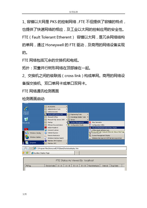
1、容错以太网是PKS的控制网络,FTE不但提供了容错的特点,也提供了快速网络的相应,及工业以太网的控制应用的安全性。
FTE(Fault Tolerant Etherent)容错以太网,是冗余网络结构的单网,通过Honeywell的FTE驱动,及商用的网络设备实现的。
FTE网络包括冗余的交换机和电缆。
拓扑:双重并行树形网络在顶部接在一起。
2、交换机之间的级联线(cross link)构成单网。
商用的网络设备指交换机、双口单网卡或单口双网卡。
FTE网络通讯检测画面检测画面启动3、系统必须有控制器、服务器、操作站组成。
4、FTE网络包括冗余交换机和电缆。
树网:连接到A交换机上A口形成的网叫A网(Yellow tree)。
连接到B交换机上B口形成的网叫B网(Green tree)。
Localhost 接收数据节点。
FLEX操作站(F站):过程数据及相关的报警和事件,还有其他数据信息,直接来自服务器;组态ES-F两种连接方法:固定连接方法(Static):提供了特定ES-F的一种永久性专用连接。
轮替连接方法(Rotary):提供了一种按需的连接,适用不需要全日制操作访问时。
Console操作站(C站):过程数据及相关的报警和事件,直接来自于控制器;其他数据信息来自于服务器;Console Extension操作站(CE):过程数据及相关的报警和事件,还有其他数据信息,全部信息都来自与C站。
7、一个C300控制器带有两个IOLINK,每个IOLINK最多支持40个IO卡件,而一个控制器最多支持64个IO卡件。
每套C300控制器最多支持64个IO Units(IOU)。
C300控制器必须与控制防火墙连接。
C300控制器主控制器FTE地址设定奇数,备用控制器地址为主控制器的地址+1。
Control Firewall(CF9)控制防火墙:在FTE网络中是成对出现的,8+1口,其中有一个专门的网线路口用于向上连接交换机,其余的8个网口可以连接控制器。
Honeywell 液位传感器 说明书

液位传感器特点:●准确的液位测量●高等级密封●小巧和可靠●快速反应●运用多种液体●不同外型和安装形式●客户可定制●容易安装●经济描述:霍尼韦尔液位传感器系列给设计工程师提供了通用而且可靠的液位测量产品,他们可以使用在极其化学性和极端温度的环境下。
LL 系列为TTL兼容。
LRN提供了大电流切换的能力。
概述:霍尼韦尔LL 系列液位开关可提供非常准确、可靠的液位测量。
1个LED 和1个的光电接收器被放入塑料的半圆球内,根据光的内部反射原理,当无液体时,绝大多数LED 光都会被光电接收器接收到,当液位覆盖球表面时,圆球顶与液体截面的折射系数发生变化,光电接收器接收到LED 光将会减少,因此输出将会发生变化,开/关输出信号能直接与PLC 相连。
传感元件被密封在聚砜铸模圆球内,外壳为聚砜,镀镍黄铜或不锈钢,能用于测量多种液体。
传感器能承受362psi 的压力及85˚C 的使用温度(高温型为125˚C ),聚砜(polysulfone )铸模圆环是一种理想的热塑材料,能抵抗诸如-酸液、碱液、盐液、洗洁精和碳氢油的侵袭。
典型运用:●储存罐-高、低液位报警、储存罐满或空● 冷却液位传感● 压缩机● 机械加工-有无润滑和切削油检测● 汽车、重型机械、铁路设备的油箱液位检测选型举例:型号普通型LL101000LL102000LL103000LL104000LL105000LL20500-1LL20500-1LL305002-1LL305012-1高温型LL101101LL102101LL103101LL10401LL105100LL205102-1LL205112-1LL305102-1LL305112-1描述7mm,M12x1螺纹,外部安装7mm,M12x1螺纹,外部安装10mm,M12x1螺纹,外部安装推入型,ø16.5-17.5,外部安装推入型, ø10,内部安装180mm 导线/护套1m 导线/护套180mm 导线/护套1m 导线/护套特点:●工业环境使用-镀镍黄铜或不锈钢,内置电源电压稳压器,固态结构,密封● 对许多有害的化学物质及压力的抵抗力-聚砜铸模圆球● 高性能-宽范围测量介质,快速响应 ,高重复性● 准确的液位测量● 高价值-低成本,无须维修● 安装容易指标工作模式重复性(mm )迟滞(mm)反应时间机械指标安装端子材料尺寸环境指标工作温度(˚C)使用温度湿度振动/冲击压力(bar )(仅指螺纹传感器)环境光线限制(mW/cm 2)电气指标供电电压(Vcc)LED(Vf)供电电流输出沉电流(Io)用户定义的单点开/关±11(根据液体)液体上升-50us液位下降-1s max (乙醇)其他液体反应时间根据其粘度内部安装/外部安装可选250mm 引线(标准)蓝 0v黑 Anode 正极绿 Output 红 Vcc园顶 聚矾或Trogamid 外壳 不锈钢或镀镍黄铜园顶螺纹六角塑料3.5mm radius M12 x 119mm 标准:高温标准高温-20 to 85-40 to 125-40 to 100-50 to 150对性能无影响认证试验20到2000Hz 在20g 时MIL-STD-883B2007.10- 5(塑料外壳)0-25(金属外壳)0.5(在工作时)-40˚C to +85˚C +85˚C to 125˚C @25˚C Optoschmit(Is)LED(I led)@25˚C @125˚C1.2V@40mA Typ.8mA Typ 30 to 40mA 40mA max 20mA max5到16V 5±0.2V在空气中液位传感器工作在液体中液位传感器工作注:常温型内含腈橡胶(nitrile)O 型圈,高温型内含氟化橡胶(viton)型圈金属3.5mm radius 1/2"BSPT 24mm聚矾不锈钢镀镍黄铜推荐型号LL101000LL101101LL103101类型常温高温高温请与Honeywell办事处和代理商联系电气连接警告:传感器LED输出(黑线)不能与电源直接相边,必须串接限流电阻。
HONEYWELL 霍尼韦尔电位器 说明书
常用型号选型样本霍尼韦尔电位器Best Seller of Evectric Materials领导地位的跨国公司。
在全球,其业务涉及航空产品、技术及服务;住宅和商业楼宇控制、工业控制技术、产品和服务以及自动化产品和服务;特种化学、纤维、塑料、电子和先进材料技术、以及产品和服务;交通和动力技术、产品和服务等领域。
霍尼韦尔在全球95个国家拥有10万员工,总部设在美国新泽西州莫里斯镇。
在纽约、伦敦、芝加哥和太平洋证券市场的交易代码为HON,为道琼斯工业指数的30家构成公司之一,也是“标准普尔500指数”的组成部分。
2002年,霍尼韦尔的销售额为223亿美元;在全球财富500强排名榜中列第195位。
传感与控制元件部霍尼韦尔公司(Honeywell)创立于1885年,从楼宇恒温控制装置开始,经过110余年的发展。
已经成为一个拥有120,000多名员工,年销售额达240亿多美元的全球化集团公司。
为工业楼宇设备和航天、航空应用提供各类传感器、控制产品和系统。
目前在全世界九十多个国家设有工厂、研究机构、销售和服务中心,在全球控制领域中处于领先地位。
Mircro Switch(微型开关公司)创立于1935,后加入霍尼韦尔成为霍尼韦尔传感与控制战略单元。
目前共有20多个系列近六万种产品,在全世界拥有三十万用户。
近半个世纪以来,霍尼韦尔公司的传感与控制分部以其优秀的产品质量和可靠性,以及不断的技术创新,不仅在北美、而且在全世界赢得了很高的声誉。
霍尼韦尔电位器 21.编码器 Encoder388E系列 (3)510系列 (4)350E11/350E16系列 (6)600系列 (8)2.电位器Potentiometers(1) 陶瓷电位器309系列 (9)409系列 (10)591系列 (11)(2)导电塑料电位器308系列 (13)408系列 (14)380系列 (15)381系列 (16)392和RV6系列 (18)53C和RV4系列 (20)574系列 (22)575系列576系列(3) 绕线电位器43系列 RA20 (24)58系列 RA30 (26)(4) 碳膜电位器585系列 (28)586系列(5) 合成碳膜电位器 (29)(6) 开关电位器 (42)(7) 电动工具专用型 (46)(8) 精密电位器Precision Potentiometers578系列 (47)73系列 ..................... (48)MKV系列 (49)MK11系列 (50)Sensor Cube (51)(10) 预调电位器 (52)(11) 玻璃釉预调电位器 (56)3. 微调电位器Trimmers Arthur343系列 (60)363系列 (61)364系列 (62)530B系列 (63)4. 绕线电阻Wirewound Resistors wMark SongCMC系列 (65)SC系列 (66)VC系列 (67)VK系列 (68)VP线绕电阻系列 (69)VP可调线绕电阻系列 (70)VPR系列 (71)5. 绕线电位器53B010/53B/030/53B050 (72)53B13/53B14/53B11 (72)57B3/57B7 (72)3霍尼韦尔电位器 4特点●小体积●防尘●模块化结构高性能,●机械寿命超过100,00转有4脉冲16定位和6脉冲24 定位两种●2位格莱码输出可扩展与推-推、推-拉和自复位开 关●配合宽泛的温度使用范围 -40°C~100°C应用●液位控制●指针控制●频率控制●温度控制●时间控制●位置反馈订货文件填写388EN-4P 388EN-6P-DJ其中: 388EN 为系列号4P, 6P 表示每周脉冲数,DJ 表示Dome Switch接触电阻2.5K Ohms max.额定电压/电流 5 Vdc at 5 mA绝缘电阻100 MOhms at 50 Vdc耐电压900 Vac at ATM机械行程/速度/寿命连续, 最大30转/分钟,寿命100000转定位数16, 24转动力矩0,007 Nm to 0,39 Nm工作温度-40 ℃ to 100 ℃ [-40 0F to 212 0F]冲击振动100 G, MIL-STD-202Dome Switch 类型SPST 自复位Dome Switch 触点容量125 mA at 28 Vdc Dome Switch 机械寿命25,000 次Dome Switch 接触电阻小于 10 Ohms Dome Switch 绝缘电阻 1 MOhmDome Switch 耐电压对地750 V; 300 V across terminalsUNSPSC Code 0,34 kg [12 oz], nominal Dome Switch 长度of Throw0,381 mm [0.015 in] nominal UNSPSC Code30211929UNSPSC Commodity30211929 Encoders产品波形频率L频率R等幅波循环388E 尺寸(仅供参考) MM[IN]配件表层直径配件表层最大限度代表性数值尺寸(仅供参考) MM[IN]螺纹直径轴衬轴连接388E 机械的编码器,4或6fe 电子脉冲并瞬间与单轴接通直径直径5特点●提供一个2-bit 格莱码表示相对位置,或者4-bit格莱码表示绝对位置。