TF70WI套管头通用使用说明书
顶驱套管送入工具设计说明书

新型顶驱套管送入工具设计目录第一章绪论 (3)1.1 引言 (3)1.2 设计目的及意义 (3)1.3 设计主要内容 (4)1.4 设计方法 (5)1.5 技术路线 (5)1.6 国内外技术现状调研 (6)1.6.1国外技术现状 (6)1.6.2国内技术现状 (7)第二章总体要求及总体方案设计 (9)2.1 顶驱套管送入工具的总体要求 (9)2.1.1依据套管载荷提出的要求 (9)2.1.2根据套管钻井扭矩提出的要求 (10)2.1.3其他参数的设计要求 (10)2.2总体结构方案设计 (12)2.2.1总体方案示意图 (12)2.2.2总体方案设计内容 (13)2.2.3驱动方式方案设计 (13)2.2.4夹持机构方案设计 (14)2.2.5其他部件的方案设计 (15)第三章顶驱下套管工具的结构设计 (17)3.1夹持机构的设计和计算 (17)3.1.1卡瓦结构的设计和计算 (17)3.1.2卡瓦座结构设计和计算 (25)3.2驱动机构设计和计算 (30)3.2.1上凸轮结构设计和计算 (31)3.2.2振动筛结构方案设计及计算 (35)3.3其他零部件的设计........................................................ 错误!未定义书签。
第四章强度校核........................................................................ 错误!未定义书签。
4.1危险点分析.................................................................... 错误!未定义书签。
4.2危险点强度校核............................................................ 错误!未定义书签。
第五章工艺、安装与保养.......................................................... 错误!未定义书签。
TM-T70II商品说明书

What’s in the Box . . . . . . . . . . . . . . . . . . . . . . . . . . . . . . . . . . . . . . . . . . . . . . . . . . . . . . . . . . . . 2 Accessories . . . . . . . . . . . . . . . . . . . . . . . . . . . . . . . . . . . . . . . . . . . . . . . . . . . . . . . . . . . . . . . . . 2 Printer Specifications . . . . . . . . . . . . . . . . . . . . . . . . . . . . . . . . . . . . . . . . . . . . . . . . . . . . . . . . . 2 Printing. . . . . . . . . . . . . . . . . . . . . . . . . . . . . . . . . . . . . . . . . . . . . . . . . . . . . . . . . . . . . . . . . . 2 Interfaces. . . . . . . . . . . . . . . . . . . . . . . . . . . . . . . . . . . . . . . . . . . . . . . . . . . . . . . . . . . . . . . . 2 Media . . . . . . . . . . . . . . . . . . . . . . . . . . . . . . . . . . . . . . . . . . . . . . . . . . . . . . . . . . . . . . . . . . . . . 2 Reliability . . . . . . . . . . . . . . . . . . . . . . . . . . . . . . . . . . . . . . . . . . . . . . . . . . . . . . . . . . . . . . . . . . . 2 Safety . . . . . . . . . . . . . . . . . . . . . . . . . . . . . . . . . . . . . . . . . . . . . . . . . . . . . . . . . . . . . . . . . . . . . 3 Dimensions . . . . . . . . . . . . . . . . . . . . . . . . . . . . . . . . . . . . . . . . . . . . . . . . . . . . . . . . . . . . . . . . . 3 Memory Switches/Receipt Enhancement Functions . . . . . . . . . . . . . . . . . . . . . . . . . . . . . . . . . 3 Memory Switches . . . . . . . . . . . . . . . . . . . . . . . . . . . . . . . . . . . . . . . . . . . . . . . . . . . . . . . . .3 Receipt Enhancement Functions. . . . . . . . . . . . . . . . . . . . . . . . . . . . . . . . . . . . . . . . . . . . . . 3 Control Panel . . . . . . . . . . . . . . . . . . . . . . . . . . . . . . . . . . . . . . . . . . . . . . . . . . . . . . . . . . . . . . . . 3 Loading Paper . . . . . . . . . . . . . . . . . . . . . . . . . . . . . . . . . . . . . . . . . . . . . . . . . . . . . . . . . . . . . . . 3 Testing the Printer . . . . . . . . . . . . . . . . . . . . . . . . . . . . . . . . . . . . . . . . . . . . . . . . . . . . . . . . . . . . 4 Removing a Paper Jam . . . . . . . . . . . . . . . . . . . . . . . . . . . . . . . . . . . . . . . . . . . . . . . . . . . . . . . . 4 Cleaning the Thermal Head . . . . . . . . . . . . . . . . . . . . . . . . . . . . . . . . . . . . . . . . . . . . . . . . . . . . . 4What’s in the Box❏Printer❏Setup Guide❏Small thermal paper roll (for operational testing)❏Power supply and AC cable❏CD (includes drivers, utilities, and manuals)❏Power switch cover❏Locking wire saddle (for routing USB cable)AccessoriesPrinter SpecificationsPrintingPrint method:thermal line printingDot density:180 dpi × 180 dpi(dpi = dots per inch [25.4 mm])Print width: 2.83" (72.2 mm), 512 dots Characters per line:font A: 42, font B: 56Print direction:unidirectional with friction feedPrint speed:9.84"/sec. (250 mm/sec.) maximum Paper feed speed:approx. 7.87"/sec. [200 mm/sec.](continuous paper feed)Character sets:alphanumeric: 95 characters;international: 18 sets;extended graphics: 128 × 43 pages(including user-defined page) InterfacesBuilt-in:USB 2.0 Full-speedOptional:serial, parallel, Powered USB, Ethernet,and wirelessMediaPaper type:thermal roll paperPaper size:80 mm wideReliabilityPrint head life:120 million pulses, 120 km Mechanism:17 million linesAutocutter: 1.7 million cutsMTBF:360,000 hoursMCBF:65 million linesFeed buttonPaper LEDError LEDPower LEDconnector(optional)Option Model Part number AC adapter (with AC cable)PS-180C825343AC adapter (without AC cable)PS-180C825341AC cable AC CABLE205498100 Interface boards UB series see price sheet Cable connector cover OT-CC70II C32C8146062 - Epson TM-T70IISafetyEMI:FCC Class ACAN ICES-3(A)/NMB-3(A)Safety Standards:UL60950-1CSA C22.2 No 60950-1DimensionsDimensions(H × W × D): 4.49" × 4.92" × 7.64"(114 mm × 125 mm × 194 mm) Weight:approx. 3.75 lb (1.7 kg)Memory Switches/Receipt Enhancement FunctionsUse the TM-T70II Utility, Memory Switch Setting Mode, or ESC/POS commands to set the memory switches and receipt enhancement functions listed below. See your TM-T70II documentation for more information.Memory Switches❏Receive buffer capacity❏BUSY condition❏Processing when data receive error❏Auto line feed❏USB power-saving function❏Release condition of receive buffer BUSY❏Paper sensor to output paper-end signals default❏Error signal output❏Print density❏Multi-tone print density❏Print speed❏Number of head energizing parts❏Character code table default❏International character default❏Interface selection❏Autocutting after closing cover❏Paper reduction❏Font A auto replacement❏Font B auto replacement❏Buzzer ❏TM-T88V command-compatible mode❏Communication condition of serial interface❏Communication condition of USB interfaceReceipt Enhancement Functions❏Auto top logo❏Auto bottom logo❏Auto top/bottom logo extended functionsControl Panel(Power) LEDOn when the power is on.Note: Turn off the printer before opening the printer cover.Error LEDSteadily on when the printer is offline. Blinking if there is an error. See if the printer cover is open. Turn the printer off for a few seconds, then turn the printer back on. If the LED is still blinking, contact a dealer or qualified service person.Paper LEDComes on when roll paper is low or out. Flashes when the printer is performing a self-test.Feed ButtonPressing this button once feeds paper by one line. Holding this button down feeds paper continuously.Loading PaperWarning: To avoid injury, do not touch any part of the printer other than the roll paper when the printer cover is open.Caution: Do not open the printer cover when the printer is printing or feeding paper; you may damage the printer. Only use paper that meets specifications, and do not use rolls that have the paper glued onto the core.1.Turn off the printer.2.Press the cover open lever to open the printer cover.Epson TM-T70II - 33.Remove the used roll paper core, if there is one, and insertthe roll paper in the direction shown below.4.Pull out some paper, and make sure it sits between the paperguides.5.Close the printer cover.6.Tear off the extra paper using the manual cutter.Testing the PrinterFollow these steps to perform a self-test:1.Make sure the printer is off and the printer cover is closed.2.Press and hold the Feed button and turn on the printer.The printer prints its status and the Paper LED beginsflashing.3.To continue the self-test, press the Feed button for less than1 second.The self-test is complete when *** completed *** is printed. Removing a Paper JamWarning: The thermal head can be very hot after printing. Let it cool before you remove the jammed paper. To avoid injury, do not touch any part of the printer other than the roll paper when the printer cover is open.1.Turn off the printer.2.Press the cover open lever to open the printer cover.3.Remove the jammed paper, then reinstall the roll paper.4.Close the printer cover.Cleaning the Thermal HeadEpson recommends cleaning the thermal head periodically (about every 3 months) to maintain print quality.Warning: The thermal head can be very hot after printing. Let it cool before you clean it. To avoid injury, do not touch any part of the printer other than the roll paper when the printer cover is open.Caution: Do not touch the thermal head with your fingers or any hard object; you may damage the printer.1.Turn off the printer.2.Press the cover open lever to open the printer cover.3.Clean the thermal head with a cotton swab moistened withan alcohol solvent (ethanol or isopropyl alcohol).purposes only and may be trademarks of their respective owners. Epsondisclaims any and all rights in those marks.This information is subject to change without notice.© 2013 Epson America, Inc., 7/13CPD-399004 - Epson TM-T70II。
无线HART网关SWG70商品说明说明书

Products Solutions ServicesTI00027S/04/EN/17.1871393078Technical InformationWirelessHART Fieldgate SWG70Intelligent WirelessHART gatewaywith Ethernet and RS-485 interfaceApplicationFieldgate SWG70 is a gateway for WirelessHARTnetworks. It enables WirelessHART field devices to communi-cate with each other and manages network security and connec-tivity. Fieldgate converts and saves the wireless field device data to a format that is compatible with other systems.It has Ethernet and serial interfaces to connect to host applica-tions such as SCADA tools.Your benefits•Easy commissioning and diagnosis of a self-organized WirelessHART network•Seamless integration of field device information into higher-order system applications using standardized protocols such as MODBUS, EtherNet/IP, HART-IP or OPC•Wireless configuration and management of smart field devices in a facility using FieldCare•Flexible use of Fieldgate in hazardous areas of a facilityWirelessHART Fieldgate SWG702Function and system designWirelessHART WirelessHART adds wireless capabilities to the HART protocol, while guaranteeing compatibility withexisting HART devices, commands and tools.A WirelessHART network comprises:•WirelessHART field devices•Wired field devices with a connected WirelessHART Adapter•FieldgateThe WirelessHART protocol may not be used to replace the wiring in the case of safety applicationswith a control function.WirelessHART Fieldgate SWG70The WirelessHART Fieldgate SWG70 acts as an interface between the WirelessHART network and a system that has an Ethernet or RS-485 connection.The WirelessHART Fieldgate SWG70 supports the following functions:•Wireless network configuration and management•Acquisition of data from the field devices and presentation to connected systems •MODBUS, HART, HART-IP, OPC and EtherNet/IP support for system integration •Configuration of network, Fieldgate and field devices via Web interface or FDT/DTM.Fieldgate is designed for installation in hazardous areas Zone 2. You can mount the antenna directly on the Fieldgate or remotely depending on the requirements of the application.System design The WirelessHART Fieldgate stores information received from the WirelessHART Adapter SWA70or other WirelessHART field devices in a buffer which can be accessed by a host application via anEthernet or RS-485 connection. The figure shows a Fieldgate operating in a typical meshed Wire-lessHART network architecture.1Host application 2Ethernet 3WirelessHART Fieldgate4Field devices with WirelessHARTWirelessHART Fieldgate SWG703InputCommunication interface WirelessHART communication interface (IEC 62591)Transmission rate Nominal 250 kbits/s Transmission range 2.4 GHz (ISM band)RangeUp to 250 m outdoors, up to 50 m indoorsTransmission power Configurable to 0 dBm or 10 dBm, for adapting to national regulations Input variables•Process variables according to HART standard are sent to the network by the field devices in the burst mode.•Up to 250 WirelessHART-based devices can be connected.OutputOverview of versions and protocolsAll Fieldgate SWG70 versions feature an Ethernet interface and a serial interface. Depending on the device version, this interface can support different protocols.1)For OPC, there is an OPC DA server. The software is included in the scope of delivery and must be installed ona Windows PC.Ethernet (via MODBUS-TCP or OPC)Communication interfaces Configurable for HART-IP and MODBUS-TCP communication Protocols HART-IP, MODBUS-TCP and also OPC serverPhysical layer Ethernet 10 BASE-T/100 BASE-TX, complete galvanic isolation Transmission rate 100 Mbit/s (max. cable length 100 m at 25 °C ambient temperature)Type of protection NoneMaximum bus length 100 m (110 yds) depending upon cableConnection facilities•7-port terminal block•Screw terminals: 0.2 mm 2 to 4 mm 2 for solid wire and 0.2 mm 2 to 2.5 mm 2 for stranded wiresFieldgateSWG70 version Interface Protocol MODBUS EtherNet/IP HART-IP AMS SWG70-xx-1ModbusEthernet X –X X Serial (RS-485)X –X –SWG70-xx-2MODBUS + OPC 1)Ethernet X –X X Serial (RS-485)X –X –SWG70-xx-3EtherNet/IPEthernet –X X X Serial (RS-485)––X–WirelessHART Fieldgate SWG704Ethernet (via EtherNet/IP)Communication interfaces Configurable for HART-IP and EtherNet/IP communicationProtocols HART-IP and EtherNet/IPPhysical layer Ethernet 10 BASE-T/100 BASE-TX, complete galvanic isolationTransmission rate100 Mbit/s (max. cable length 100 m at 25 °C ambient temperature)Type of protection NoneMaximum bus length100 m (110 yds) depending upon cableConnection facilities M12 connectorRS-485 serial interfaceCommunication interfaces Configurable for HART Version 7.0 or MODBUS RTU communicationTransmission rate Hardware or software configurable between 1200 Bit/s to 115200 Bit/sType of protection NoneGalvanic isolation Fully isolated from all other circuitsMaximum bus length1200 m (1230 yds), depending upon cable and transmission rateTerminal resistor Integrated, settable by hardware (DIP-switch) or softwareConnection facilities•Two 3-port terminal blocks, allowing series connection of several Fieldgates•Screw terminals: 0.2 mm2 to 4 mm2 for solid wire and 0.2 mm2 to 2.5 mm2 for stranded wiresPower supplyPower supply20 VDC to 30 VDC SELV / PELVPower<5 WConnection facilities•Two 2-port terminal blocks, 2nd port for redundant power supply•Screw terminals: 0.2 mm2 to 4 mm2 for solid wire, 0.2 mm2 to 2.5 mm2 for stranded wiresWirelessHART Fieldgate SWG705Operating conditionsApplication rangeThe Fieldgate SWG70 serves as a gateway for WirelessHART networks.The WirelessHART protocol may not be used to replace the wiring in the case of safety applications with a control function.Installation conditionsInstallation instructionsEnvironmentAmbient temperature range –20°C to +60°C (–4°F to 140°F)Storage temperature –40°C to +85°C (–40°F to +185°F)Relative humidity 5% to 95%, non-condensingVibration resistance EN 60068-2-6: 10 Hz ≤ f ≤ 150 Hz/1g Shock resistance EN 60068-2-27: 15 g, 11 msElectromagnetic compatibilityThe WirelessHART Fieldgate meets EU Directive 2004/108/EC "Electromagnetic compatibility"•EN 61326:– Interference immunity: EN 61326-1, 2006, Industry – Interference emission: EN 61326-1, 2006, Class ALocation:Avoid mounting the WirelessHART Fieldgate near a pipe or high-voltage equipment wherever possible.Where possible, the WirelessHART Fieldgate should be in radio contact with at least 20% of all wireless field devices or adapters.Under typical conditions, the maximum spacing is 250m outdoors and 50m indoors.Installation: A remote antenna can be mounted outside a cabinet.Orientation:With vertical antenna.Protection against lightning:If there is a risk of lightning, install suitable antenna accessories. See “Accessories” on page 7.Connect the protective ground to the protective ground connection of the Fieldgate housing. The minimum cross-section of the protective ground is 2.5mm 2.Hazardous area:Fieldgates with the appropriate certification (see ordering information) can be mounted in Zone 2.The housing cover can be removed in Zone 2 to view the LEDs. It is not permitted to operate any switches in an explosive atmosphere.WirelessHART Fieldgate SWG706Mechanical ConstructionOverall dimensionsWeight Approx. 1.6 kgHousing•Material: Painted aluminum•Color: Light gray, RAL 7035Degree of protection IP 66 / IP 67Antenna•Omnidirectional dipole antenna•Remote antennas: See “Accessories” on page7.OperationConfiguration•Web browser via Ethernet•FieldCare via Ethernet (HART IP CommDTM) or RS-485 (serial CommDTM)Operating elements•2x Pushbuttons within housing for selecting operating mode during local configuration•5x LEDs within housing for indicating current operating mode during local configuration•1x 8-position DIP switch for HART device address (1 to 4),baudrate of RS485 interface (5 to 6), terminating resistor (7) and security mode (8)hardware settings can be overwritten by software settings.IP address•Configurable via Web browser or DTM, default 192.168.1.1•The EtherNet/IP version of Fieldgate uses DHCP to assign the IP addressConfigurable functions•Wireless network•HART, MODBUS and Ethernet communication interfacesWirelessHART Fieldgate SWG707Diagnosis•Display of wireless field device list with process values of selected field device•Display of wireless field device list with burst message identification of selected field device •Network monitoring of wireless communication events •Diagnostic functionAccessoriesAntenna accessoriesNote the following when selecting accessories for the antenna:•The Ex approval for Fieldgate SWG70 is only valid for the 2dBi antenna supplied.•The antenna must comply with the rules for the usage of 2.4GHz equipment that apply in the country of installation. In case of doubt, please contact a regional expert for radio approvals.•The gain is calculated from the difference in the antenna gain and the losses of the individual components such as the cables and surge arrester. The gain may not exceed the 2dBi limit.•The WirelessHART range of the Fieldgate SWG70 depends on the coaxial cable used (attenuation) between the Fieldgate and the antenna.Fig.1: Calculating the maximum gain of a remote antenna1Antenna2Coaxial adapter3RF coaxial cable with connectors4Surge arrester, λ/4, without mechanical fixing 5Fieldgate SWG70Order No.Description Fig. No.Antenna gain (Gain)Loss (attenuation)71131503Remote panel antenna Kit incl. coaxial adapter and mounting bracket 1 and 28.5 dBi –71131502Remote dipole antenna Kit incl. coaxial adapter 1 and 2 6.0 dBi –71131504Remote cabinet antenna Kit incl. coaxial adapter 1 and 2 6.0 dBi –71131509Coaxial cable 2.5 m 3–0.5 dB 71131508Coaxial cable 5 m 3– 1.1 dB 71131507Coaxial cable 10 m 3– 2.1 dB 71131506Coaxial cable 15 m3– 3.2 dB 71131505Surge arrester (protection against lightning) 4–0.2 dBWirelessHART Fieldgate SWG708Ordering informationProduct structureDetailed information about the product structure is available:•On the Endress+Hauser website: /SWG70•From your Endress+Hauser Sales Center: Accessories•Remote antennas and antenna accessories: See “Accessories” on page 7.•Additional accessories on requestDocumentationWirelessHART Fieldgate SWG70Certificates and ApprovalsCE MarkThe WirelessHART Fieldgate SWG70 meets the legal requirements of the relevant EU directives. Endress+Hauser confirms successful testing of the WirelessHART Fieldgate SWG70 by affixing to it the CE mark.Hazardous area approvalsSee the "Documentation" section.IT securityEthernet interfaceThe Fieldgate SWG70 is equipped with security mechanisms to protect it against any inadvertent changes to the device settings. Additional IT security measures in line with operators' security stan-dards and designed to provide additional protection for the device and device data transfer must be implemented by the operators themselves.If network firewalls are used, the following TCP/IP ports must be specifically open:❑WirelessHART Fieldgate SWG70Operating Instructions BA00064S/04/en ❑Wireless Adapter and FieldgateCompetence Brochure CP00013S/04/en ❑WirelessHART Fieldgate SWG70Safety Instructions ATEX /IECEx XA00001S/04/a3❑WirelessHART Adapter SWA70Operating Instructions BA00061S/04/en❑WirelessHART-Fieldgate SWG70Control Drawing XA01565S/04/enPort Service UseAccess to67/UDP,68/UDP Client IP address assignment via DHCP Fieldgate IP address (write)53/UDP,53/TCP Client DNS: name resolution 443/TCPServerHTTPS over SSL: Web server – Fieldgate configurationFieldgate (read and write),AES-128-bit-SSL-encrypted, additionally password-protected 502/TCP Server System integration via MODBUS/TCPProcess values (read only)5094/TCP 5094/UDP Server Operation via DTM and OPC server system integration via HART-IP Fieldgate and WirelessHART devices (read and write)33333Server AMS system integrationFieldgate and WirelessHART devices(read and write)44818/TCP,2222/UDPServerSystem integration via EtherNet/IPFieldgate and WirelessHART devices (read and write)WirelessHART Fieldgate SWG709WirelessHART interface Security is implemented with end-to-end sessions utilizing industry standard AES-128-bit encryption For more information see: /hcp/tech/wihart/wihart_security.htmlRadio approvalsTelecommunication approvals•Europe: Radio Equipment Directive•USA and Canada: FCC Part 15.247 for wireless applications in the 2.4 GHz frequency band •Brazil: ANATEL UL-BR 15.0983 (EAN Number: 7898994191414) •China: CMIIT ID (SRRC)•Japan: Ministry of internal affairs and communication •Mexico: COFETEL RCEPNSW12-0651•Other national certificates are available on request.Additional national guidelines to be observed:Europe This device complies with the requirements of the EC Radio Equipment Directive 2014/53/EU.•ETSI EN 300 328: V1.8.1:2012USA and Canada This device complies with part 15 of the FCC Rules.This device complies with CFR 47, Part 15 of the FCC Rules. The operation of this device is subject to the following two conditions:(1) This device may not cause harmful interference, and (2) this device must accept any interference received, including interference that may cause undesired operation.Country GuidelineBulgaria General authorization required for outdoor use and public service Italy If used outside of own premises, general authorization is required.Norway May be restricted in the geographical area within a 20 km radius from the center of Ny-Alesund.Romania Use on a secondary basis. Individual license requiredLatviaThe outdoor usage of the 2.4 GHz band requires an authorization from the Electronic Communications Office.WirelessHART Fieldgate SWG7010BrazilANATEL UL-BR 15.0983 (EAN Number: 7898994191414)“Este produto está homologado pela ANATEL, de acordo com os procedimentos regulamentados pela Resolução 242/2000, e atende aos requisitos técnicos aplicados.”Para maiores informações, consulte o site da ANATEL .brChineseThis device has been granted a type approval by the SRRC (State Radio Regulatory Commission of P. R. China): CMIIT ID 2011DJ5309JapaneseThis device has been granted a designation number by the Japanese Ministry of Internal Affairs andCommunications according to the Ordinance concerning Technical Regulations Conformity Certifica-tion etc. of Specified Radio Equipment ( )•Article 2 clause 1 item 19•Approval n°: 202WW09117712This device should not be modified (otherwise the granted designation number will be invalid).MexicoCOFETEL Approval No.: RCPENSW12-0651La operación de este equipo está sujeta a las siguientes dos condiciones:(1) es posible que este equipo o dispositivo no cause interferencia perjudicial y (2) este equipo o dis-positivo debe aceptar cualquier interferencia, incluyendo la que pueda causar su operación no deseada.WirelessHART Fieldgate SWG7011WirelessHART Fieldgate SWG70 。
WirelessHART 适配器 SWA70 商品说明书

TI00026S/04/en/13.1071128571Technical InformationWirelessHART Adapter SWA70Intelligent WirelessHART interface module for connection to 4...20 mA/HART devicesApplicationWirelessHART Adapter SWA70 is a battery powered, interface module that connects HART and 4...20 mA devices to a WirelessHART network. The adapter is suitable for several applications, for example:•Tank and silo monitoring/Inventory control:Measured values together with device and battery status are transmitted at regular intervals to a higher level system•Access to installed base:Additional diagnosis information is extracted from existing wired HART devices and sent to a plant asset management tool, e.g. FieldCare •Condition monitoring of equipment:Wireless devices are added at critical points in the plant not normally connected to the control room due to accessibilty or wiring costs. Improved data flow and diagnostics increase plant reliability and safety. •Process optimization:Temporary connection of the WirelessHART Adapter allows plant sections to be monitored and optimised at little cost and effort.Features and Benefits•HART devices quickly upgraded to WirelessHART technology•4...20 mA devices quickly integrated into the WirelessHART network•One 4...20 mA or up to four HART devices can be connected (in multidrop mode) to one adapter •Burst mode and event notification supported for adapter and connected devices•Remote and difficult-to-access HART devices connected to the plant control room without expensive cables•Tanks and silos integrated at minimal cost into e.g. SupplyCare Inventory Control software•Endress+Hauser and 3rd party devices maintainable with open FieldCare Plant Asset Mangement software •Network configuration also done within FieldCare Plant Asset Management software•Supports configuration with FDT and DD-basednetwork toolsWirelessHART Adapter SWA702Endress+HauserFunction and System DesignWirelessHARTWirelessHART is a HART Communication Foundation specification for use in process automation. It adds wireless capabilities to the HART protocol while maintaining compatibility with existing HART devices, commands, and tools.A WirelessHART network comprises: •Wireless field devices•Non-wireless field devices enhanced by using a WirelessHART adapter•Gateways that enable communication between devices and host applications•A Network & Security Manager responsible for configuring, managing and monitoring the networkWirelessHART Adapter SWA70Endress+Hauser’s SWA70 WirelessHART Adapter has been designed to act as an add-on interface for any HART or 4...20 mA device. It supports the following functions:•Powering of one HART or one 4...20 mA device;alternatively, connection of up to four externally powered HART devices in multidrop mode •Scaling of current signal supplied by a connected 4...20 mA device•Burst mode and event notification for both itself and the connected devices.The battery has been specially selected to give long life when used in monitoring applications.System designWirelessHART Adapter SWA70 transmits its information to a host application through a WirelessHART Fieldgate. The figure below shows a typical meshed WirelessHART network architecture.e.g. ControlCare P ViewAsset Management e.g. FieldCareInventory Controle.g. SupplyCareFieldgateField devicewith SWA70 adapterWirelessHART Adapter SWA70InputWired interface One device input channel for: One point-to-point with a HART device, orOne point-to-point connection with a 4...20 mA device, orUp to four externally powered HART devices operating in multidrop mode Communication type HART communication in multidrop mode, 4...20 mA current signal in point-to-point modeProtocol version HART Version 7.0 (backwards compatible with previous HART versions)Transmission rate1200 bits/s for HART multidropType of protection Intrinsically safe and dust Ex versions available, see Ordering InformationDevice loop-power Current: 4 mA to 20mA DC (according to NAMUR recommendation NE 43) or4 mA when operating in multidrop mode (one device only)Fault current:I ≤ 3.6 mA or I ≥21 mAProtection:Short-circuit protected, triggered for currents > 25 mASupply voltage:8 VDC to 23 VDCConnection facilities6-port terminal block, screw terminals:Cable Adapter mounted directly on device: cables suppliedSeparately mounted adapter: standard installation cableDevice connection Connection of loop-powered devices (adapter powered) and externally powered 4-wire devicesEndress+Hauser3WirelessHART Adapter SWA70Connection of loop-powered devices with external power supplyOutputWireless interface WirelessHART communication interfaceTransmission rate Nominal 250 kBits/sOperating frequency 2.4 GHz (ISM band)Transmission range Under reference conditions: Outdoor 250 m, indoor 50 mRF power level Configurable 0 dBm or 10 dBm, depending upon national regulationsOutput variables Output configurable according to user requirement•Adapter: loop-current and up to three other variables selectable from adapter temperature, batteryvoltage, energy consumed, estimated battery life-time• 4...20 mA device: scaled or linearized process value•HART device: up to four process variables (configured through Fieldgate/gateway)Additional functions•Burst mode, configurable for up to eight variables from adapter and/or connected device(s)•Event notification, configurable for up to eight variables from adapter and/or connected device(s)•Fault recognition and scaling or linearization of 4...20 mA signal of connected analog device•Monitoring of energy consumption•Locking/unlocking of device parameterizationDiagnosis Diagnosis function in accordance with NAMUR NE 107, ASM and HART recommendationsPower SupplyPower supply Special long life lithium thionylchloride battery packSupply voltage 5 VDC to 7.2 VDCBattery rating19 Ah nominal capacity at 20°CBattery life5–7 years, dependent upon update rate of process variables, instrument type and environmental conditions 4Endress+HauserWirelessHART Adapter SWA70Endress+Hauser 5PerformanceApplies to analog current signal circuit.Reference conditions to IEC 61298 Part 2Measured error 4...20 mA circuit:0.125% of span Influence of ambient temperature4...20 mA circuit:5 μA/10KOperating ConditionsInstallationInstallation instructionsLocation:If possible, avoid mounting too near walls, pipes, heavy-duty electrical equipment etc.If possible, the adapter should be in line of sight with a neighbouring adapter or the Fieldgate Maximum separation 250 m outdoors, 50 m indoorsMounting:Direct mounting on field device or separately mounted on wall (wall mounting kit available)Orientation:Preferably with antenna verticalEnvironmentClimate ClassEN 60721-3-4:4K4H, suitable for stationary use in unprotected outdoor locationsAmbient temperature range–40°C to +80°C, -40°F to 176°FAt temperatures below –30°C/–22°F the battery pack capacity decreases rapidly Storage temperature–40°C to +85°C/–40°F to +185°F without battery pack<21°C/+70°F with battery pack - recommended to minimize self discharging Vibration resistance EN 60068-2-64:20 Hz ≤ f ≤ 2000 Hz: 0.01g²/Hz Shock resistanceEN 60068-2-27:15 g, 11 msElectromagnetic compatibilityThis device complies with the requirements of the EC Directive 2004/108/EG "Electromagnetic Compatibility".•IEC 61326 / EN 61326:– Immunity:EN 61326-1: 2006, Table 2 (industrial locations)– Emission: EN 61326-1: 2006, Class B•NAMUR recommendation EMC (NE 21), ESD behaviour "B"•EN 301 489-1/17WirelessHART Adapter SWA70Mechanical ConstructionOverall dimensions W x H x D: 111.5 mm x 189.9 mm x 92.8 mmWeight0.5 kg, without battery pack0.785 kg, with battery packHousing Material: PBT FR or aluminium, see ordering InformationColour: Light grey, RAL 7035 with blue logoDegree of protection IP 65, IP 66; NEMA Type 4Cable entry Two separate M20x1.5 threaded entries for direct and separate mountingMounting adapter M20x1.5 to M20x1.5, M20x1.5 to G 1/2, M20x1.5 to NPT 1/2, M20x1.5 to NPT 3/4,see Ordering InformationAntenna Omnidirectional dipole antenna, position adjustable in vertical plane.6Endress+HauserWirelessHART Adapter SWA70Endress+Hauser 7OperabilityConfiguration•Local with FieldCare via HART modem and DTM for SWA70•Remote with FieldCare via WirelessHART Fieldgate SWG70 and DTMs for SWA70 and SWG70•Remote with Device Description (DD) based tool via DD based gatewayOperating elements•Pushbutton within housing for selecting operating mode during local configuration •LED within housing for indicating current operating mode during local configurationDevice address Configurable between 0...63 via DD or DTM, default 15Ordering InformationProduct StructureWirelessHART Adapter SWA70Approvals AA BE B1CA C1I1IENon-hazardous areaATEX II 2G Ex ia IIC T4ATEX II 2G Ex ia IIC T4 Gb, ATEX II 2D Ex tb [ia] IIIC IP6x T70°C Db CSA general purposeCSA C/US IS Cl.I,II,III Div.1 Gp.A-G, NI Cl.I Div.2 AEx ia IECEx Ex ia IIC T4 Gb, IECEx Ex tb [ia] IIIC T70°C Db IECEx Ex ia IIC T4 Gb Transmitter Interface 194-20 mA HART Special version HousingA B Y F32, Polyester IP66F33, Aluminium IP66Special versionAuxiliary Energy 159Battery. lithium metal, built-in, transport class 9/2, UN3091Prepared for battery Special version VersionA B C Y Prepared for installation on devicePrepared for installation separate from devicewith wall/pipe mounting kit and M20 cable glandPrepared for installation as router with wall/pipe mounting kit Special versionConnection Adapter 123489Thread M20Thread G 1/2Thread NPT 1/2Thread NPT 3/4WithoutSpecial version ServicesIK IW Customized configurationWithout tooling DVD (FieldCare Setup)IdentificationZ1Measuring point tag52006326:Wired on tag plate, stainless steel 52006327: Paper sticker52006329: Supplier label/plateSWA70-Product designationWirelessHART Adapter SWA70DocumentationWirelessHART Adapter SWA70Certificates and ApprovalsCE MarkIn attaching the CE Mark, Endress+Hauser confirms that WirelessHART Adapter SWA70 conforms to all relevant EU directives.Telecommunication Compliance•ETSI (R&TTE)•FCC Part 15.247 for wireless applications in the area of 2.4 GHz •EN 300 328•Additional national certificates on requestHazardous area approvals See Ordering Information❑WirelessHART Adapter SWA70Operating Instructions BA061S/04/en❑WirelessHART Adapter and Fieldgate Competence Brochure CP013S/04/enTI00026S/04/en/13.10CCS/FM9.0Instruments InternationalEndress+HauserInstruments International AG Kaegenstrasse 24153 Reinach SwitzerlandTel.+41 61 715 81 00Fax +41 61 715 25 ***************.com。
Schurter PG07 70°C 接线器说明书
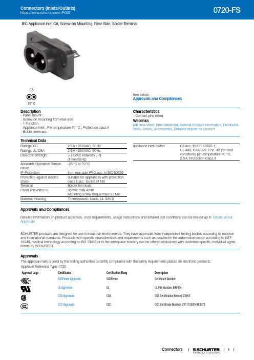
1IEC Appliance Inlet C8, Screw-on Mounting, Rear Side, Solder TerminalSee below:Approvals and CompliancesC870° CDescription- Panel mount :Screw-on mounting from rear-side - 1 Function- Appliance Inlet , Pin temperature 70 °C , Protection class II - Solder terminalsCharacteristics - Contact pins rolledWeblinkspdf data sheet , html datasheet , General Product Information , Distributor-Stock-Check , Accessories , Detailed request for productT echnical DataRatings IEC2.5 A / 250 VAC; 50 Hz Ratings UL/CSA 2.5 A / 250 VAC; 60 Hz Dielectric Strength> 2 kVAC between L-N (1 min/50 Hz)Allowable Operation Tempe-rature-25 °C to 70 °CIP-Protectionfrom rear-side IP40 acc. to IEC 60529Protection against electric shock Suitable for appliances with protection class II acc. to IEC 61140TerminalSolder terminals Panel Thickness S Screw: max 4 mmMounting screw torque max 0.5 Nm Material: HousingThermoplastic, black, UL 94V-0appliance inlet/-outletC8 acc. to IEC 60320-1,UL 498, CSA C22.2 no. 42 (for cold conditions) pin-temperature 70 °C, 2.5 A, Protection Class IIApprovals and CompliancesDetailed information on product approvals, code requirements, usage instructions and detailed test conditions can be looked up in Details about ApprovalsSCHURTER products are designed for use in industrial environments. They have approvals from independent testing bodies according to national and international standards. Products with specific characteristics and requirements such as required in the automotive sector according to IATF 16949, medical technology according to ISO 13485 or in the aerospace industry can be offered exclusively with customer-specific, individual agree-ments by SCHURTER.ApprovalsThe approval mark is used by the testing authorities to certify compliance with the safety requirements placed on electronic products. Approval Reference T ype: 0720Approval LogoCertificates Certification Body Description SGSFimko Approvals SGSFimko Certificate Number: UL Approvals UL UL File Number: E96454CSA Approvals CSACSA Certification Record: 73165CCC ApprovalsCCCCCC Certificate Number: 2011010204483973Product standardsProduct standards that are referencedOrganization Design StandardDescriptionDesigned according to IEC 60320-1Appliance couplers for household and similar general purposesDesigned according to UL 498Standard for Attachment Plugs and ReceptaclesDesigned according to CSA C22.2 no. 42General Use Receptacles, Attachment Plugs, and Similar Wiring Devices Application standardsApplication standards where the product can be usedOrganization Design StandardDescriptionDesigned for applications acc.IEC/UL 60950IEC 60950-1 includes the basic requirements for the safety of informationtechnology equipment.CompliancesThe product complies with following Guide LinesIdentification Details Initiator DescriptionCE declaration of conformity SCHURTER AG The CE marking declares that the product complies with the applicablerequirements laid down in the harmonisation of Community legislation onits affixing in accordance with EU Regulation 765/2008.RoHS SCHURTER AG Directive RoHS 2011/65/EU, Amendment (EU) 2015/863China RoHS SCHURTER AG The law SJ / T 11363-2006 (China RoHS) has been in force since 1 March2007. It is similar to the EU directive RoHS.REACH SCHURTER AG On 1 June 2007, Regulation (EC) No 1907/2006 on the Registration,Evaluation, Authorization and Restriction of Chemicals 1 (abbreviated as"REACH") entered into force.Dimensions [mm]0720-FSSolder terminals for wiresAll VariantsPackaging unit 100 Pcs2Mating Outlets/ConnectorsCategory / DescriptionPower Cord Overview completeCord Sets 2.5 A, IEC Connector, Black, 2.0 m, H03VVH2-F 2x0,75mm2, Connector IEC C7, 001500 mm, H03VVH2-F2G0.75, black6013.0474Cord Sets 2.5 A, IEC Connector, Black, 4.0 m, H03VVH2-F 2x0,75mm2, Connector IEC C7, 001500 mm, H05VVH2-F2G0.75, black6013.0478Kabelverbindung/2.5, IEC Connector, Black, 2.0 m, H03VVH2-F 2x0,75mm2, Connector IEC C7, 001500 mm,H03VVH2-F2G0.75, black6051.0015Power Cord further types to 0720-FSPower Supply Cord Overview completeCord Sets 2.5 A, North America, Black, 2.0 m, SVT 2x18AWG, Connector IEC C7, 002500 mm, NISPT-2, black6010.5274Cord Sets 2.5 A, North America, Black, 4.0 m, SVT 2x18AWG, Connector IEC C7, 002500 mm, NISPT-2, black6010.5278Kabelverbindung/2.5, North America, Black, 2.5 SVT 2x18AWG, IEC C7, 002500 mm, SVT 2x18 AWG, black6051.0018Power Supply Cord further types to 0720-FSThe specifications, descriptions and illustrations indicated in this document are based on currentinformation. All content is subject to modifications and amendments. Information furnished is believed26.11.2193。
VICTOR 70F说明书 万用表

厂商声明胜利高公司向最初购买该仪表的购买者承诺:自购买之日起一年内在正常使用情况下给予保修,并免费更换材料(不包括保险丝、测试表笔)。
本公司不承担在不正常的条件下操作使用万用表而造成的对仪表和人员造成的损害。
要获得本公司的服务,请与本公司最近的仪器服务中心联系或将产品连同有关产生问题的说明、邮资一起寄到最近的仪器服务中心。
本公司不承担在邮递当中的损害,本公司将免费维修或更换出错的产品或退还您所购买产品的费用。
然而,如果本公司检测出这些错误是由于误用、更换、事故或不正常的条件下使用或操作而引起的,您将要为维修而付维修费,维修好的产品将退回给您。
运回产品维修或校准仪表应该经过统一包装“快递”到本公司。
仪表应该被装在出厂纸板箱里以便运输。
如果没有可用的纸箱,使用大小合适的牢固的容器进行包装,如果使用替代品,仪表应该用纸预先包装,并且用类似的减震材料围在周围。
对最初购买者有关在运输中的损坏声明仪表运送到购买者处,购买者应立即全面检查仪表,盒子里的所有材料应该对照附带的包装单进行核对检查。
如果仪表以任何方式损坏,应及时通知运送者。
如要修理由于运输而损坏的仪表,请与最近的胜利仪器服务中心联系。
由于运输损坏与运输公司的赔偿协商应由顾客来完成。
使用本手册注意事项●本用户手册内容如有改变,恕不另行通知。
●本用户手册的内容被认为是正确的,若用户发现有错误、遗漏等,请与生产厂家联系。
●本公司不承担由于用户错误操作所引起的事故和危害。
●本用户手册所述的功能不作为将本产品用作特殊用途的理由。
24/2目录1、概述 (4)2、开箱检查 (5)3、安全注意事项 (6)4、安全符号说明 (7)5、仪表面板及按键功能说明 (8)6、按键开关………………………………………………………………………………………9-107、显示屏幕………………………………………………………………………………………11-128、特性 (13)9、直流电压(DCV) (14)10、交流电压(ACV) (15)11、直流电流(DCA) (16)12、交流电流(ACA) (17)13、电阻 (18)14、二极管及通断测试 (19)15、电容(C) (20)16、频率(Hz)及仪表保养………………………………………………………………………21-2324/3一.概述VICTOR70F一种智能型、性能稳定、高可靠性、3 3/4数字多用表,仪表采用33mm字高LCD 显示器,读数清晰,显示直观,操作方便,可用来测量直流电压、交流电压、直流电流、交流电流、电阻、电容、频率、二极管及通断测试;同时还有单位符号显示、数据保持(HOLD)、最大最小値测量(MAX/MIN),相对值测量(REL),数据存储(SAVE),数据读取(MEM),时间显示(year/month/day/hour/minute/second),自动/手动量程转换(AUTO/RANGE)、自动断电及报警功能(15分钟)、采用面板校准技术。
套管头使用及安装.

2001.8.15
JMP
套 管头
卡瓦式 螺纹式 焊接式
套管头是用于钻 井过程中对井口 压力进行控制的 重要设备 与表层 采用API 6A碳钢 或低合金钢制造 套管连接 适用套管程序: 20“×13-3/8 ” ×9-5/8 “×7 ”×5-1/2 “, 或用户要求
2001.8.15
JMP
2001.8.15
JMP
套管头技术介绍
1、套管头结构型式简介 2、套管头型式试验 3、套管头2000年-2001年销售业绩 4、典型套管头介绍 5、典型套管头安装程序
2001.8.15
JMP
套管头
套管头采用是符合API SPEC 6A规范的低合金钢或不锈钢制 造而成 套管头是钻井过程中,控制井 口压力的重要设备 侧出口带有VR堵螺纹
板深 6 井、 8井、 5 井千米桥区 块滩海区块。
金属密封套管头 二层三卡瓦套管头 复合式套管头 三层四卡瓦套管头 卡瓦式套管头
螺纹式套管头(LCSG)
大港油田
3 4 5 6 7
中科院钻探中心
江苏东海“科探井” 路良区块
文28井、沙特项目、濮光区块。
新疆石油局 中原油田 江苏油田 胜利油田
胜利油田(海洋)
8 9
TF13-3/8”x7”-35Mpa TF13-3/8”x9-5/8”x7”-70Mpa TF13-3/8” x7”-70Mpa
10 11 12
TF13-3/8”x9-5/8”x6-5/8”35Mpa TF13-3/8”x7”-70Mpa TF13-3/8”x9-5/8”x7”-70Mpa
中国石油技术开 发公司 青海油田 吐哈油田
TLS电子70HDBaseT传输器与接收器说明书
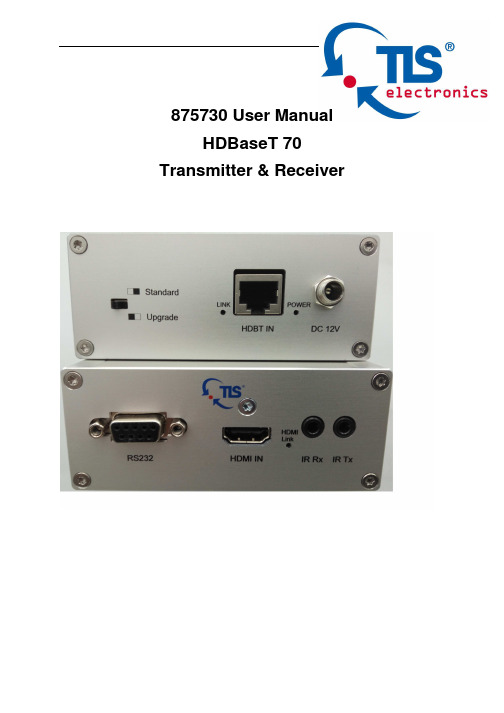
875730 User ManualHDBaseT 70 Transmitter & Receiver875730 User manualTLSelectronicsGmbHContact:************************Thank you for purchasing this product. For optimum performance and safety, please read these instructions carefully before connecting, operating or adjusting this product. Please keep this manual for future reference.SURGE PROTECTION DEVICE RECOMMENDED This product contains sensitive electrical components that may be damaged by electrical spikes, surges, electric shock, lightning strikes, etc. Use of surge protection systems is highly recommended in order to protect and extend the life of your equipment.875730 User manualTLSelectronicsGmbHContact:************************Table of Contents1. Introduction.........................................................................................4 2. Features...............................................................................................4 3. Panel Description..................................................................................5 4. Connection Diagram....................................................................9 5. Specifications.......................................................................................9 6. Package Contents................................................................................10 7. Maintenance.......................................................................................10 8. Warranty Policy.................................................................................10 9. Limitations of Warranty...............................................................................11 10. Exclusive Remedies.................................................................................12 11. RMA Policy (12)875730 User manualTLSelectronicsGmbHContact:************************IntroductionTLS HDBaseT 70 transmitter and receiver is a 70m (230ft) HDBaseT Extender. It transmits 1080P@60HZ at 48bit deep color via single Cat5e-AWG24-cable up to 70 meters (230ft). Bi-directional IR and RS232 can also be transmitted over the same cable. With support of POH (power over HDBaseT), only one power supply is needed at either transmitter or receiver.Features• HDMI v1.4 and HDCP compliant, support 1080p@60Hz, 3D, 4Kx2K@30Hz • Support 1080P@60Hz or VESA: 1920x1200@60Hz up to 70m (230ft) • Dolby TrueHD and DTS-HD master audio pass through HDMI output • Bi-Directional IR and RS232 pass through.• Power over HDBaseT supported, only one power supply needed at either transmitter or receiver side •With ESD ProtectionNote :The POH function is designed for powering compatible transmitter or receiver units of TLS only.875730 User manualTLSelectronicsGmbHContact:************************Panel Description875730 Transmitter1. RS232 connector2. HDMI link indicator3. IR TX jack4. HDMI input5.IR RX jack875730 User manualTLSelectronicsGmbHContact:************************1. Signal Link indicator2. Power status indicator3. EDID DIP switch ( UP=0, DOWN=1)[DIP]=0000: HDMI 1080p@60Hz, Audio 2CH PCM[DIP]=0001: HDMI 1080p@60Hz, Audio 5.1CH PCM/DTS/DOLBY [DIP]=0010: HDMI 1080p@60Hz, Audio 7.1CH PCM/DTS/DOLBY/HD [DIP]=0011: HDMI 1080i@60Hz, Audio 2CH PCM[DIP]=0100: HDMI 1080i@60Hz, Audio 5.1CH PCM/DTS/DOLBY [DIP]=0101: HDMI 1080i@60Hz, Audio 7.1CH PCM/DTS/DOLBY/HD [DIP]=0110: HDMI 1080p@60Hz/3D, Audio 2CH PCM[DIP]=0111: HDMI 1080p@60Hz/3D, Audio 5.1CH PCM/DTS/DOLBY [DIP]=1000: HDMI 1080p@60Hz/3D, Audio 7.1CH PCM/DTS/DOLBY/HD [DIP]=1001: HDMI 4K2K, Audio 2CH PCM[DIP]=1010: HDMI 4K2K, Audio 5.1CH PCM/DTS/DOLBY [DIP]=1011: HDMI 4K2K, Audio 7.1CH PCM/DTS/DOLBY/HD [DIP]=1100: DVI 1280x1024@60Hz, Audio None [DIP]=1101: DVI 1920x1080@60Hz, Audio None [DIP]=1110: DVI 1920x1200@60Hz, Audio None [DIP]=1111: EDID pass throughNOTE :The port will only read the DIP switch settings on power-up. The device must be powered offand then back on again for it to implement any change of the DIP switch settings.4. Upgrades DIP switch5. HDBT output6. DC 12V screw type connector875730 User manualTLSelectronicsGmbHContact:************************875730 Receiver1. Signal Link indicator2. Power status indicator3. Standard/Upgrade mode switch4. HDBT input5. DC 12V screw type connector875730 User manual TLSelectronicsGmbHContact:************************1. RS232 connector2. HDMI link indicator3. IR TX jack4. HDMI output5.IR RX jack875730 User manualTLSelectronicsGmbHContact:************************Connection DiagramSpecificationsBandwidth 2.97Gbps per Color Video input Transmitter 1XHDMI Type A, 19-pin, female Receiver 1xRJ45 Video output Transmitter 1xRJ45 Receiver 1XHDMI Type A, 19-pin, female IR input 2x3.5mm stereo jack IR output2x3.5mm stereo jack RS232 control 2x DB9Power Supply12V/2A DC, screw type connector Power Consumption 9.5WAudioPasses up to Dolby TrueHD or DTS-HD Master Audio Resolution Video: up to 4Kx2KVESA: up to 1920x1200Distance 230ft @ 1080p over CAT5e/6-AWG24 130ft @ 4Kx2K over CAT5e/6-AWG24 Dimensions 107x107x27mm Weight200gTemperature Operating 32°F to 104°F (0°C to 40°C) Storage-4°F to 140°F (20°C to 60°C) Rack-MountableRack ears includedNOTE : Specifications are subject to change without notice. Weight and dimensions are approximate .875730 User manualTLSelectronicsGmbHContact:*************************Package Contents• 1x 875730 Transmitter • 1x 875730 Receiver• 1x 12V/2A DC power supply• 1x IR Transmitter, 1x IR Receiver.MaintenanceClean this unit with a soft, dry cloth. Never use alcohol, paint thinner or benzene to clean this unit.Warranty PolicyTLS electronics products are warranted against defects in material and workmanship for two years from the date of shipment. During the warrantyperiod, TLS electronics will, at its option, repair or replace products that prove to be defective. Repairs are warranted for the remainder of the original warranty or a 90 day extended warranty, whichever is longer.For equipment under warranty, the owner is responsible for freight to TLS electronics and all related customs, taxes, tariffs, insurance, etc. TLSelectronics is responsible for the freight charges only for return of the equipment from the factory to the owner. TLS electronics will return the equipment by the same method (i.e., Air, Express, Surface) as the equipment was sent to TLS electronics.875730 User manualTLSelectronicsGmbHContact:*************************All equipment returned for warranty repair must have a valid RMA number issued prior to return and be marked clearly on the return packaging. TLS electronics strongly recommends all equipment be returned in its original packaging.TLS electronics obligations under this warranty are limited to repair orreplacement of failed parts, and the return shipment to the buyer of the repaired or replaced parts.Limitations of WarrantyThe warranty does not apply to any part of a product that has been installed, altered, repaired, or misused in any way that, in the opinion of TLS electronics, would affect the reliability or detracts from the performance of any part of the product, or is damaged as the result of use in a way or with equipment that had not been previously approved by TLS electronics.The warranty does not apply to any product or parts thereof where the serial number or the serial number of any of its parts has been altered, defaced, or removed.The warranty does not cover damage or loss incurred in transportation of the product.The warranty does not cover replacement or repair necessitated by loss or damage from any cause beyond the control of TLS electronics, such as lightning or other natural and weather related events or wartime environments. The warranty does not cover any labor involved in the removal and orreinstallation of warranted equipment or parts on site, or any labor required to diagnose the necessity for repair or replacement.The warranty excludes any responsibility by TLS electronics for incidental or consequential damages arising from the use of the equipment or products, or forany inability to use them either separate from or in combination with any other equipment or products.A fixed charge established for each product will be imposed for all equipment returned for warranty repair where TLS electronics cannot identify the cause of the reported failure.875730 User manual TLSelectronicsGmbHContact:*************************Exclusive RemediesTLS electronics ’s warranty, as stated is in lieu of all other warranties, expressed, implied, or statutory, including those of merchantability and fitness for aparticular purpose. The buyer shall pass on to any purchaser, lessee, or other user of TLS electronics ’s products, the aforementioned warranty, and shall indemnify and hold harmless TLS electronics from any claims or liability of such purchaser, lessee, or user based upon allegations that the buyer, its agents, or employees have made additional warranties or representations as to product preference or use.The remedies provided herein are the buyer ’s sole and exclusive remedies. TLS electronics shall not be liable for any direct, indirect, special, incidental, or consequential damages, whether based on contract, tort, or any other legal theory.RMA PolicyWhen returning product to TLS electronics for any reason, the customer should fill out the official RMA form to obtain a RMA number. Without the permission or approval, TLS electronics will be no responsible for any return.This can be initiated by emailing or calling your related sales.All requests are processed within 48 hours.Standard ReplacementFor customers that agree to return defective product to TLS electronics first, a Standard Replacement option is available.An RMA number must first be issued by sales. This RMA number will need to be referenced on the outside of the return shipment.Upon receipt of the defective product, TLS electronics will, at its discretion, either repair or replace the product and ship it out in the most expeditious875730 User manualTLSelectronicsGmbHContact:*************************manner possible. Subject to availability, the replacement product will be shipped on the business day following receipt of the defective product.In the event the product returned to TLS electronics has been discontinued (i.e. the product is no longer being manufactured by TLS electronics but is still under warranty), TLS electronics will, at its discretion, either repair or replace with recertified product.Once you have obtained an RMA numberAfter obtaining an RMA number from TLS electronics, you must send theproduct - freight prepaid - to TLS electronics. The TLS electronics RMA number must be prominently displayed on the outside of your package. If you send your product to TLS electronics without the RMA number prominently displayed on the outside of the package, it will be returned to you unopened.Please use a shipping company that can demonstrate proof of delivery. TLS electronics does not accept responsibility for any lost shipments unless proof of delivery to TLS electronics is provided.Please note:Product shipped to TLS electronics must be properly packaged to prevent loss or damage in transit.Shipping your RMA to TLS electronics using regular mailing envelopes is not acceptable, as they do not protect the product from damage during shipping.TLS electronics will not repair or replace a module that is shipped in such a way that the product is not properly protected.TLS electronics will not accept any product that has been damaged as a result of accident, abuse, misuse, natural or personal disaster, or any unauthorized disassemble, repair or modification .。
- 1、下载文档前请自行甄别文档内容的完整性,平台不提供额外的编辑、内容补充、找答案等附加服务。
- 2、"仅部分预览"的文档,不可在线预览部分如存在完整性等问题,可反馈申请退款(可完整预览的文档不适用该条件!)。
- 3、如文档侵犯您的权益,请联系客服反馈,我们会尽快为您处理(人工客服工作时间:9:00-18:30)。
1.概述1.1用途及适用范围:T F133/8"×95/8"×7"-70W I(简称T F70W I)套管头是由金湖石油机械有限公司根据西北局需要研制的产品,主要用来固定钻进井的井口,连接井下套管柱可靠地密封和控制管间的环形空间,是油田采油(气)井口装置的重要设备。
1.2规格、型号:TF 20"×133/8"×95/8"×7"- 70 WI套管头改型设计号导管工作压力表层套管油层套管技术套管1.3适用条件:额定工作压力:70M pa(10000PS I)额定温度:-29℃-121℃(P U级)工作介质:石油、天然气、泥浆、抗HS21.4安全性能:产品从设计、选材、性能试验、出厂试验都符合A PI s pe c 6A«井口和采油树设备规范»的要求,故只要按照使用说明书要求正确操作,则本设备工作是安全可靠的。
2.结构特征与工作原理2.1总体结构特点:此套管头主要由套管头、套管四通、套管悬挂器和阀门等部件组成。
其结构紧凑,连接牢固,密封可靠,安装调试方便。
2.2主要部件结构特点2 .2 .1套管头本体(图1)2.2.1.1套管头法兰及旁侧口通径均符合AP I s pe c 6A标准,具有良好的互换性。
2.2.1.2套管头底部为133/8″B CSG螺纹式,可直接于133/8″套管连接,安装方便。
2.2.2.3套管头侧出口为21/16″×5000PSI R24法兰连接。
2.2.1.4套管头法兰上的顶丝用于顶住防磨套。
2.2.1.5套管头内腔设计为95/8″“W”型单锥面卡瓦悬挂器坐落台肩。
1、顶丝总成2、“W”型95/8″套管悬挂器3、21/16″×5000PSI手动平板阀4、133/8″BCSG图1:TF133/8″×95/8″-70套管头(01部分)2. 2.2套管四通本体(图2)2.2.2.1 套管四通法兰及旁侧口通径均符合AP I s p ec 6A标准,具有良好的互换性。
2.2.2.2套管四通底部采用两道95/8″B T圈密封,这种密封结构通过在高压下把密封脂经单向阀注入到“B T”型密封圈,挤压缩“BT”型密封圈,起到密封作用,且可以在两道BT圈之间试压。
2.2.2.3套管四通侧出口为29/16"×10000ps i栽丝法兰,并带VR堵螺纹,可以在不压井的情况下更换阀门。
2.2.2.4套管四通上法兰带有顶丝,用于顶住防磨套。
下法兰有试压孔,用于检查环空和两道B T圈的密封情况。
1、顶丝总成2、“W”型7″套管悬挂器3、29/16″×10000PSI手动平板阀4、95/8″BT密封圈图2:TF95/8″×7″-70WI套管头(02部分)2.2.2.5套管四通内腔设计为7″“W”型单锥面卡瓦悬挂器坐落台。
2.2.3套管悬挂器(图3)95/8″、7″套管悬挂器采用“W”型单锥面卡瓦悬挂器、依靠套管自重卡住套管,使卡瓦与套管形成牢靠的连接,密封形式为自激式密封,卡瓦悬挂器为剖分式、自锁结构,安装快捷方便。
1、提绳2、卡瓦牙3、卡瓦壳体4、手柄5、橡胶密封环6、支撑座7、手柄图3:95/8″(7″)“W”型套管悬挂器2. 2.4手动平板阀(附图4)2.2.4.1主要承压件采用符合AP I sp ec 6A中材料性能要求的合金钢制造而成,工作安全可靠。
2.2.4.2手动平板阀阀板与阀座为金属密封,表面喷(堆)焊硬质合金,具有良好的耐磨、耐腐蚀性能。
2.2.4.3 阀体和阀盖间采用螺柱连接,并采用了新型的金属密封,简化了结构,保证了密封性能。
2.2.4.4 阀体和阀座间装有回复性能高的波形弹簧,使阀座带有预紧力,从而使阀座和阀板间在低压力时仍保持良好的密封性能。
2.2.4.5阀杆密封填料采用特殊结构的复合材料制造,在保证密封性能的情况下,降低了阀门开关力矩。
2.2.4.6阀杆设有倒密封结构,以便阀门在使用中处于额定工作压力的情况下能更换阀杆密封填料。
2.2.4.7轴承座上设有专门润滑轴承的油嘴,便于现场加注润滑脂。
2.2.4.8阀盖一侧设有密封脂注入阀,以便现场补注密封脂,提高阀板、阀座的密封性能及润滑性能。
1、护套2、阀杆3、轴承螺母4、轴承座5、轴承6、“O”型圈7、阀板8、阀体9、密封脂注入阀10、尾杆11、尾杆盘根压帽12、护罩13、手轮14、阀杆盘根压帽15、波型弹簧16、阀座17、护板18、钢圈19、密封圈20、垫片21、阀盖22、油杯23、垫圈24、螺母25、双头螺栓26、紧定螺钉手动明杆平板阀示意图图43.技术特性3.1主要性能:产品规范级别:PSL1-3性能要求级别:P R1-2额定材料级别:AA B B CC D D EE F F3.2主要参数:连接形式:AP I S p ec 6A法兰连接法兰规范:套管头上法兰:135/8"×5000p si(BX160)套管四通上法兰:11"×10000ps i(B X158)旁侧口:套管头旁侧口:21/16"×5000ps i (R24)套管四通旁侧口:29/16"×10000p si(B X153)套管程序:133/8"×95/8"×7"4.尺寸及重量4.1外形尺寸:套管头:长×宽×高:1240×750×518(c m)套管四通:长×宽×高:1650×670×725(c m)4.2重量净重:套管头1120K g 套管四通1400Kg5.安装程序本说明书按常规的钻井工艺编写安装操作程序,在准备初始装井口前,建议用户根据所用钻井架底座的高度和图中所给定的具体高度,确定一个四周由水泥加固的方井,这在钻井和地面井场布置设计中应予考虑的因素之一。
5.1 套管头安装程序5.1.1 用钻头钻至设计井深,起出钻具,下入133/8"表层套管至预定位置,固井、候凝。
5.1.2将套管头通过底部133/8"BC SG螺纹与133/8"表层套管相连,确保方向正确。
(图5)1、顶丝总成2、“W”型95/8″套管悬挂器3、21/16″×5000PSI手动平板阀4、133/8″BCSG图5:TF133/8″×95/8″-70WI套管头(01部分)5.1.3 为了保持刚性的节流压井管汇出口管线距在地面高度不变,防止浅层气,需在套管头上安装替代四通,防喷器组,泥浆出口管。
5.1.4将133/8"试压塞与钻杆相连,并通过泥浆出口管,防喷器组,替代四通将试压塞送入,使其坐落在套管头台肩上。
5.1.5 关防喷器,由钻杆泵入5000ps i(35M p a)水压,对各连接部位进行试压,检查各处密封情况。
5.1.6 试压成功后,先泄压,后打开防喷器,取回133/8"试压塞。
5.1.7 由钻杆连接送入取出工具和133/8"防磨套并通过防喷器组下入133/8"防磨套,做好有关标记,拧进法兰上四只顶丝,以便顶住防磨套,注意触及到防磨套即可,不要顶的过紧,以免挤扁防磨套,退回送入取出工具。
5.1.8 用121/4"钻头钻至设计井深,起出钻具,退回四只顶丝,用送入取出工具收回133/8"防磨套。
5.1.9 下入95/8"套管至预定位置,固井、候凝。
5.1.10 拆去套管头与替代四通之间螺栓、螺帽,上提防喷器组。
5.1.11 在套管头法兰上,横跨放置两木板(或专用工具)用以支承95/8"套管挂组件。
5.1.12 上提95/8"套管,使其产生4-5吨超张力。
5.1.13 对准剖分式95/8"套管悬挂器的导向定位销,下手柄不动,上手柄旋转套管悬挂器为90˚,合抱住95/8"套管由下而上逐一卸出手柄,移去木板(或专用工具),使95/8"套管悬挂器组件坐落到套管头的台肩上,让卡瓦抱住套管,然后放松95/8"套管。
(图6)1、上手柄2、卡瓦壳体3、下手轮4、卡瓦牙5、套管6、提绳7、橡胶密封环 8、支撑座 9、木板 10、移去木板 11、上手柄旋转90°下手柄不动图6:套管悬挂器安装5.1.14 在距法兰面上大约63/4"(170m m)处,切割95/8"套管,并将切口倒呈6×30°坡口,并打磨光滑,待安装套管四通。
5.2 套管四通安装程序5.2.1 用清洗剂清洗套管四通内腔B T密封槽和套管短柱的密封面,检查套管的外圆是否有表面缺陷。
5.2.2 用清质油涂抹B T密封件,将其安放到套管四通内腔密封槽中。
5.2.3清洗套管头、钢圈槽,并在钢圈槽内放置清洁无损的BX160垫环,然后小心将套管四通从95/8"套管上方慢慢套入,用螺栓固定两法兰直至两法兰面间隙为零。
5.2.4卸去套管四通下部135/8"法兰上的两只标有“注塑孔”字样注塑阀螺母,并拆去对面“观察孔”上下的丝堵。
5.2.5注入枪装满EM08密封脂,通过软管连接到注塑阀上。
5.2.6操作注入枪,注入密封脂,同时观察对面的开启孔,直到开启孔口有密封脂溢出,上紧丝堵。
5.2.7继续操作注入枪,挤入密封脂,达到工作压力或套管抗外挤强度的80%,取两者之一低值。
1、套管四通2、观察孔3、试压孔4、套管头5、注塑试压枪6、套管图7:套管四通注塑示意图5.2.8另一注塑接头按 5.2.5-5.2.7程序重复操作。
(图7)5.2.9操作试压枪,从标有最上面的“试压孔”字样的注塑阀上,泵入35MP a或套管抗外挤强度的80%水压,取两者低值,检查两道B T密封之间密封性能,如无泄漏,卸压力为零。
5.2.10再从对最下面的另一“试压孔”字样的注塑阀上,泵入35MP a 或套管抗外挤压强度的80%水压,两者取低值,检查BT密封,密封钢圈,套管挂的密封性能,如无泄漏,卸压力为零。
5.2.11 95/8"B T密封试压合格后,安装替代四通防喷器组,泥浆出口管,下入11"试压塞,对各连接部位试压,检查各处密封情况,试压方法参见 5.1.4、5.1.5,试压合格后,先卸压,后打开防喷器。
5.2.12取出试压塞,通过钻杆和送入取出工具,下11"防磨套,法兰上的四只顶丝,以顶住防磨套,注意触及到防磨套即可,不要顶的过紧,以免挤扁防套磨套,退回送入取出工具。
5.2.13 用81/2″钻头钻至设计井深,起出钻具退回顶丝,用送入取出工具收回防磨套。
5.2.14下入7"套管至预定位置,固井,候凝。
5.2.15拆去套管四通与替代四通之间的螺栓螺帽,上提防喷器。
5.2.16在套管四通法兰上,横跨放置两块木板,用以支承7"套管挂组件。
5.2.17上提7"套管挂,使其产生4-5吨超张力。
5.2.18安装7"套管挂,方法同5.1.13。