西门子RWD60控制器说明书
西门子S7-200智能型CPU CR60用户手册说明书

6ES7288-1CR60-0AA0
SIMATIC S7-200 SMART, CPU CR60, compact CPU, AC/DC/relay, onboard I/O: 36 DI 24 V DC; 24 DO relay 2A; Power supply: AC 85264 V AC at 47-63 Hz, Program/data memory 20 KB
Yes; 10 V/m, 80 to 1 000 MHz (to IEC 61000-4-3); 10 V/m, 900 MHz, 1.89 GHz, 50% ED (to IEC 61000-4-3)
Interference immunity to cable-borne interference
150 ns; / instruction 1.2 µs; / instruction 3.6 µs; / instruction
32 byte; Digital inputs 32 byte; Digital outputs
Hardware clock, no battery backup Yes 7d 4 s; within 120s/month at 25 °C
Address area I/O address area ● Inputs ● Outputs
Timereal-time) ● Backup time ● Deviation per day, max.
Digital inputs Number of digital inputs Input voltage ● Type of input voltage ● Rated value (DC) ● for signal "0" ● for signal "1" Input current ● for signal "1", typ. Cable length ● shielded, max. ● unshielded, max.
西门子操作手册

目录1 安全信息 (1)术语定义 (1)前言 (1)2定位器的供货范围 (2)3组装…………………………………………………………………概述…………………………………………………………………定位器在潮湿环境中的使用……………………………………定位器在易受到强加速作用力或震动场合的使用……………直行程执行机构的连接附件………………………………………组装顺序……………………………………………………………角行程执行机构的连接附件………………………………………组装顺序………………………………………………………………4可选附件的安装……………………………………………………5电气连接……………………………………………………………6气动连接……………………………………………………………注入仪表空气开关………………………………………………..限流器………………………………………………………………7调试(见散页“操作—简要说明”)………………………………直行程执行机构调试准备…………………………………………直行程执行机构的自动初始化…………………………………直行程执行机构的手动初始化…………………………………角行程执行机构调试准备…………………………………………角行程执行机构的自动初始化…………………………………角行程执行机构的手动初始化…………………………………故障校正……………………………………阀门定位器的简明操作指南………………..附录一………………………………………………………………………附录二………………………………………………………………………1 安全信息1.2 前言本操作说明描述了定位器组装、连接、调试的基本步骤,不能取代SIPART PS2电气阀门定位器的操作手册,操作手册中包含了组装、功能、操作的详细信息。
无危险使用关于安全方面,定位器出厂时已达到完美状态,如果要保持此状态,用户必须要遵守本操作说明中安全提示。
操作手册(西门子系列)

页眉内容西门子802D数控铣床第一章数控系统面板显示屏右侧和下方的灰色方块为菜单软键,按下软键,可以进入软键左侧或上方对应的菜单。
有些菜单下有多级子菜单,当进入子菜单后,可以通过点击“返回”软键,返回上一级菜单。
精心整理第二章手动操作2.1返回参考点1.进入系统后,显示屏上方显示文字:0030:急停。
点击急停键,使急停键抬起。
这时该行文字消失;2.按下机床控制面板上的点动键,再按下参考点键,这时显示屏上按下机床控制面板上的点动键;先按下快进按键,然后再按坐标轴按键,则该轴将产生快速运动。
1.点击“设置”下方的软键;2.显示如下窗口,可以在这里设定JOG进给率、增量值等;精心整理3.使用光标键移动光标,将光标定位到需要输入数据的位置。
光标所在区域为白色高光显示。
如果刀具清单多于一页,可以使用翻页键进行翻页;4.点击数控系统面板上的数字键,输入数值;,系统进入精心整理第三章程序编辑3.1进入程序管理方式1.点击程序管理操作区域键;按下;2.点击编辑下方的软键;3.打开当前程序;精心整理4.使用面板上的光标键和功能键来进行编辑;5.删除:使用光标键,将光标落在需要删除的字符前,按删除键删除错误的内容。
或者将光标落在需要删除的字符后,按退格删除键进行删除。
点击数控系统面板上的数字键,输入数值;精心整理刀具的刀具号;例如,要建立刀具号为6的铣刀,其操作步骤如下:,显示屏如下显示:使用光标键移动光标,将光标定位到需要输入数据的位置。
光标精心整理第五章自动运行操作5.1进入自动运行方式1.按下系统控制面板上的自动方式键,系统进入自动运行方式:2.显示屏上显示自动方式窗口,显示位置、主轴值、刀具值以及当前的程序段。
5.2软键点击自动方式窗口下方菜单栏上的“程序控制”软键;;,就能恢复被停止的程序。
●中断:按复位键,可以中断程序加工,再按按数控启动键,程序将从头开始执行。
精心整理。
西门子 RWD62通用控制器 说明书
模拟信号切换 当 X2 输入的信号超过设定值, 选择为夏季运行模式. 反向动作输出信号(只有 Y1) 被设置为正向输出 (制冷).
3342s07
Y1 Y
RWD62
Y2 X2 X1
Temp.
在 D1 和 M 端子之间加一个开关可以用来实现昼 / 夜 运 行 设 定 点 的切换.
每个输出点Y (Y1, Y2) 可以被设置为反向或者正向输出. 模拟量电压输出信号 (Y…) 控制接受 DC 0…10 V 控制信号的设备.
Siemens Building Technologies HVAC Products
3/10
CE2N334cn 12.2002
举例 辅助功能 PI 限制器功能 远程设定 串级控制 最大优先权
Y1
Y2
Output Voltage
3342d05
Setpoint
2 个正向动作顺序 (应用编号: 50-59)
Load
通用输入点 X1 通用输入点 X2 数字量输入点 D1 模拟量输出点
通用输入点 X1 用于接主输入信号, 如 Landis & Staefa 的Ni 1000 温度传感器, 和Pt 1000 温度传感器或者 0…10 V DC 主动式输入信号.
安装注意事项
本章节中带警告标志部分包含技术安全要求和限制。请注意这些警示都直接涉及人身及 设备安全.
RWD62 可以按以下方式安装: 请遵守当地安装规范.
A
安装在 DIN 轨上 (EN 50 022-35 x 7.5) DIN轨至少要 120 mm 长
B
用2个螺丝安装在墙上
西门子 模块式控制器 说明书

Technical Specification SheetRev. 9, Aug. 2003模块式控制器图1: 模块式现场控制器描述模块式控制器(MBC)是APOGEE现场管理和控制系统的组成部分,它是一种高性能的模块式直接数字控制(DDC)管理的现场控制器。
现场控制器在不依靠较高层处理器的情况下,可以独立工作或连网以完成复杂的控制、监视和能源管理功能。
模块式控制器对局域网络(FLN)装置和其它现场系统(如冷冻机、锅炉、消防/人身安全设施、门禁设施和照明设备)进行中央监视和控制。
另外,可使多达100个模块式现场控制器在一个网络上进行通讯。
特征模块式的硬件组件使得将来扩充时,在匹配设备上来配合控制要求方面有很高的灵活性。
压扣式(snap-in)模块设计简化了安装与维护在箱门上的透明观察板上允许使用者观察面板上的显示状态和强制开关的位置。
集成化平台适合于通讯和与其它系统和设备的互操作。
特别编制的程序可满足设备控制方面的应用先进的比例积分微分(PID)暖通空调控制,闭环调节算法可使振荡最小,并保持精密控制。
为全套设备管理提供了安装在内部的能源管理应用程序和直接数字控制应用程序。
全面的报警管理、历史数据记录、操作员的控制监视功能。
支持符合工业标准的10/100 Base-T 的TCP/IP网络上的点对点通讯。
Technical Specification SheetRev. 9, Aug. 2003线路电源维修工具盒瞬变电流抑制和过载保护模块式监控点配置根据用户需求配置点类型和数量,来配合应用的需要 备有多种箱体尺寸,以配合点数和将来扩展的需求搭扣式(Snap-in)点终端模块分为两部份的点模块/接线组允许阶段安装,而且维修人员无需再接线,不使用任何工具即可进行维护 各模块配有独立电路,某处出现故障时,系统的其余部份并不受影响利用表面安装技术实现了小型化,可更有效地利用空间 方便读取各监控点的卷标状态/强制能力备有手动监控强制开关选项,可对输出进行控制和维护 易于看到各监控点的LED 指示灯显示,即使门关闭时也如此 强制状态点在报告中显示操作强制开关时不需动用开放式处理器(需动用电源供应器模块)模块总线点终端模块和开放式处理器之间的通讯 以62.5K bps 速率扫描监控点终端模块总线结构允许监控点终端模块以任何次序安装电源模块为点终端模块提供24Vac 和24Vdc 的电流 独立模块结构使安装和维修更方便 过压/电压不足保护及过电流保护开放式处理器具有16.67MHz 速度的摩托罗拉68302处理器,可提供快速处理 可扩充的内存能配合数据/程序储存的需要现场可编程固件使更新变得简单易行,而无须更换底板两个快速连接(RJ-11)操作终端端口用于网络的信息通讯、调制解调器支持和打印可增加调制解调器选项,以便通过电话进行通信 管理网络上的点对点通讯协调楼宇网络(FLN)设备的传输,其内容包括时间安排、警报和强制 可任意选择与其它各现场系统控制器的通讯超强处理器可提供跨TCP/IP 以太网的点对点通讯 通讯汇流 符合SCSI 工业标准 高达6M bps 速率的控制器间通讯分配24Vac 电流给电源模块和开放式处理器图2: 模块式现场控制器组件和主要特点硬件组件模块式控制器由以下四个主要部份组成:箱体组件-根据箱体内部组件的情况,有两种型号供选择。
西门子6040控制系统诊断手册说明书

What is diagnosticsThis feature of the control software is useful in testing the 1400-2 or higher, as well as RAM expansion, it will test the RS232 port, video, axis controllers, the Clock Card and Mill Interface card.Getting into DiagnosticsAt the ENTER NEXT COMMAND, type DI and press enter. Then use the code G 0 3000. All digits are numerical. Press ENTER and you should see the first page of diagnostics. You will have 5 pages and once you put in the G 0 3000 code you will be on the first page of 5 total. The SPACEBAR is used to switch pages and the ENTER key moves you from field to field.Diagnostic CommandsCOMMAND DESCRIPTIONCE Clears messages under DEDE Displays the last 48 error messagesDS Displays the machine switchesX Terminate diagnostics and exitG 0 3000 Enter diagnostics menuFunction #1 – EPROM CHECKSUM:This command reads the eproms on the 1610 module card. After performing the Checksum test, the results are displayed. This test displays four to six 1 byte numbers. They should all be zeros. If they are, the test will loop and continue to test. Press the manual key to stop the test. If you get a checksum error this indicates you have a problem with the CPU card or the software module.Function #2 – RAM Test (1400):This test performs a write/read to test the CPU onboard memory. The memory is used for things such as holding the parameters, offsets, execution buffers and general usage of the CPU. While the test is running, the current memory segment is displayed as follows:SEGMENT 6 OR 4SEGMENT 7 OR 5SEGMENT 8PASSED TEST #### OF TIMES.The message “Memory Failure” would appear and the data that failed would be displayed. A failure with this test indicates the 1400-X card needs replacing.Function #3 – RAM EXPANSION TEST (1460):This will test the same as function #2 except it checks for memory expansion to 422k.SEGMENT 9SEGMENT ASEGMENT BSEGMENT CSEGMENT DSEGMENT EPASSED TEST #### TIMES.If the card is present, it is tested automatically the same as function #2. When a card is not found, you will get the message “Not Present.”*NOTE: THERE IS A MORE THOROUGH RAM TEST AVAILABLE ON MENU PAGE 5Function #4 – RS232 Test:This function tests the RS232 port. Install the Fadal jumper or just jumper pins #2 & #3. After selecting the baud rate, the CNC sends and receives a flow of characters until a fault is found or the manual key is pressed to stop the test. There are two procedures that can be performed with this test.1)Install the jumper plug directly in the back of the CNC RS232 port and cycle the test. This tests the machine for apossible failure with the ribbon cable, wiring or a bad communications card (1030-X).2)Install the test plug at the computer’s end of the cable. This will check not only the cable but also theenvironment. A bad cable, solder connection or an electrical noise problem could cause the first test to pass and the second test to fail.Function #5 – Non-destructive loop test:This causes all tests to be continuously performed until a failure has occurred or the manual key is pressed.The table below is the diagnostic machine switch menu.DISPLAY DESCRIPTIONATCXTNDD Switch closes when the ATC slide is extendedATCTURET Switch closes momentarily when the ATC turret motion is complete. May not be seen because closure may occur between screen updates.ORIENSP Switch closes when the spindle is at the proper angle for orientation.ATCHOME Switch closes when the ATC slide is fully retracted.ATCFAULT Switch closes when the ATC is subjected to excessive up or down forces.DRAWBAR Switch closes when the drawbar cylinder is pressurized.OIL LEVEL Switch closes when the oil level is low for waylube and spindle lube reservoir.HIGH IDLER Switch closes when the idler wheel is retracted. (Low range engaged).LOW IDLER Switch closes when the idler wheel is retracted. (High range engaged).PROBE Switch is open when probe switch is engaged.SLIDE HOLD Switch is open when doors are closed (external slide hold).X Exit the switch display screen.Function #1 on page 2: Keyboard testThis will test the keyboard by echoing the key to the screen. Pressing the JOG key allows the hand wheel to be tested. Function #2 on page 2: START CNC. Do not use this command.Function #3 on page 2: 1010-4 axis controller diagnostics intended for a Fadal tech only.Function #4 on page 2: START MOS. Used by Fadal service tech only.Function #5 on page 2: ZERO MEMORY. This writes zeros to segments 6, 8, 9, A, B, C, D, E.Function #1 on page 3: VIDEO TEST. This test has two functions.1) A testing of the video ram, which you will see as a quick flicker on the screen. If a failure is found, then there is apossible failure in your 1420 card, or the 1030 card.2) A visual test. The screen should show a repeating pattern of characters. If the pattern is not repeating thenthere is a possible failure on the 1420 or the 1030 card.Function#2 of page 3: 1010 axis controller testThis tests all the axes and if a slot is not populated then the No Response counter will be incremented. If an axis slot is populated and either the No Response or Failure counter has been incremented then you have a possible 1420 video card has failed or the 1030 card or even the processor. The expected and received checksum the spindle card is F0 and 80 respectively.Function #3 of page 3: Testing the clocksAll three of the VMC clocks will be tested with this function. Interrupt 6 counts from -200 to 0 and then interrupts, interrupt 2 interrupts after approximately .1 seconds, and interrupt 3 interrupts after approximately .3 seconds. Therefore as interrupt 1 counts to 0 interrupt 3 should count to 6 (Note that the counting doesn’t have to be perfect but should be in the general area). A message should appear if an interrupt is not counting properly. A message should appear if an interrupt is not counting properly. A failure could indicate a problem with the clock card or communication problem with the computer interface (1030) or CPU.Function #4 of page 3: Test Mill Interface CardThe pass counter will be incremented with successful pass. Otherwise, a failure message will appear, which possibly indicates a 1040 or 1030 or 1400 CPU card.Function #5 of page 3: Program memory checksumThis test calculates a 4 byte checksum of all the current programs in memory. This checksum is used to verify that the memory has not been changed during a power on/off test or during a long period of time with the power off.Function #1 of page 4: Fill memory with a pattern. (Intended for a Fadal Tech only)Function #2 of page 4: Check Memory for Pattern. (Intended for a Fadal Tech only)Function #3 of page 4: Enable remote diagnostics. (Intended for a Fadal Tech only)Function #4 or page 4: Echo RS232 port data.The CNC’s back serial port will act just like a test plug. It will echo back any data that it receives on the port. Function #5 on page 4: Destructive RAM test. (Intended for a Fadal Tech only)Function #1 of page 5: Count INT1, INT2, INT6. (Intended for a Fadal Tech only)Function #2 of page 5: Full DAC with INT6 count of ed4h. (Intended for a Fadal Tech only)Function #3 of page 5: Quarter DAC with INT6 count of ed4h. (Intended for a Fadal Tech only) Function #4 of page 5: Test encoders. This will test the encoders on AC machines.Function #5 of page 5: Test ADC. (Intended for a Fadal Tech only)。
SIEMENS RWD 控制器说明
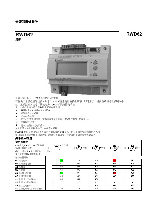
安装和调试指导RWD62运用该通用控制器用于 HVAC 系统的舒适性控制。
可提供二个模拟量输出信号用于0 ~ 10 V直流电压的模拟调节,即可用于二极供热或制冷以及制冷/供热.主模拟输入信号可被设定为C0,F0,%或没有特定单位.第二个模拟量输入信号能被用于下列应用程序:♦PI限制功能 ( 绝对值和相对值)♦远程参数设定功能♦设定点的补偿♦夏季 / 冬季模式转换 ( 模拟量或数字量的输入)(反转的供热 / 制冷输出)♦串级控制功能♦制冷 / 去湿的优先级控制独立的数字输入可提供白天 / 夜间模式转换.RWD62 控制器即可安装在开关箱内的标准的DIN导轨上也可用螺丝安装在保护外壳内.输出方式和辅助功能必须在初始化时进行参数设置,详见维护模式的参数设置流程。
菜单显示描述运用号摘要(H = 供热, C = 制冷, R = 反比例调节, D =正比例调节)(第一个数字量 = 主控制回路, 第二个数字量 = 辅控制回路)主回路#1x H or R序列#2xH + H or R + R 序列#3xH + C or R + D 序列#4xC or D序列#5xC + C orD + D 序列辅助控制回路#x0 无辅助点#10 #20 #30 #40 #50#x1 远程设定功能#11 #21 #31 #41 #51#x2 绝对值#12 #22 #32 #42 #52#x3相对值#13 #23 #33 #43 #53#x4 漂移补偿功能#14 #24 #34 #44 #54#x5 串级控制功能#15 #25 #35 #45 #55#x6冬/夏数字信号控制#16 #26 #36 - -#x7冬/夏模拟信号控制#17 #27 #37 - -#x8 最大优先控制- - #38 #48 #58#x9 主控制回路 (主动信号输入) #19 #29 #39 #49 #59RWD62Note: 运用的详细资料清单可向当地的供货商索取.如:RWD62的第30号运用号的资料代码为操作模式RWD 控制器有以下功能的操作按键: SELECT ✍ ✍ 选择键被用来进行确认和储存参数设置.通过上下按键进行参数的查看和调整. 操作超时在正常模式下调整设定参数时,如在20秒内无任何操作RWD 控制器将自动退出.但是,当处在参数设置的模式时, RWD 控制器将保持为PS 参数设置模式直至用户结束整个参数设置过程.注意仅在特定的程序或编程过程中出现相应的特定参数.如:假设第二个模拟输入未被使用,则X2的值和相应选项均不会出现.调试软件(S3341A031EN0)可进行运用号的选择和参数的调整 .该软件是基于WIN95及以上的操作平台,并可将设定的参数打印.可通过该软件对参数进行设置,从而使参数不在液晶屏上显示。
西门子 说明书
SIMATICS7/HMISIMATIC Automation Tool SDK V3.1 SP2 Product informationProduct InformationSiemens AG Division Digital Factory A5E45252984-AAⓅ 10/2018 Subject to changeCopyright © Siemens AG 2018.All rights reservedLegal informationWarning notice systemThis manual contains notices you have to observe in order to ensure your personal safety, as well as to preventdamage to property. The notices referring to your personal safety are highlighted in the manual by a safety alertsymbol, notices referring only to property damage have no safety alert symbol. These notices shown below aregraded according to the degree of danger.indicates that death or severe personal injury will result if proper precautions are not taken.WARNINGindicates that death or severe personal injury may result if proper precautions are not taken.CAUTIONindicates that minor personal injury can result if proper precautions are not taken.NOTICEindicates that property damage can result if proper precautions are not taken.If more than one degree of danger is present, the warning notice representing the highest degree of danger willbe used. A notice warning of injury to persons with a safety alert symbol may also include a warning relating toproperty damage.Qualified PersonnelThe product/system described in this documentation may be operated only by personnel qualified for the specifictask in accordance with the relevant documentation, in particular its warning notices and safety instructions.Qualified personnel are those who, based on their training and experience, are capable of identifying risks andavoiding potential hazards when working with these products/systems.Proper use of Siemens productsNote the following:WARNINGSiemens products may only be used for the applications described in the catalog and in the relevant technicaldocumentation. If products and components from other manufacturers are used, these must be recommendedor approved by Siemens. Proper transport, storage, installation, assembly, commissioning, operation andmaintenance are required to ensure that the products operate safely and without any problems. The permissibleambient conditions must be complied with. The information in the relevant documentation must be observed. TrademarksAll names identified by ® are registered trademarks of Siemens AG. The remaining trademarks in this publicationmay be trademarks whose use by third parties for their own purposes could violate the rights of the owner. Disclaimer of LiabilityWe have reviewed the contents of this publication to ensure consistency with the hardware and softwaredescribed. Since variance cannot be precluded entirely, we cannot guarantee full consistency. However, theinformation in this publication is reviewed regularly and any necessary corrections are included in subsequenteditions.Table of contents1 Components of the SIMATIC Automation Tool SDK (4)Components of the SIMATIC Automation Tool SDK 1 The SIMATIC Automation Tool Software Development Kit (SDK) consists of the followingcomponents:●Setup application for installing the SDK●SIMATIC Automation Tool Application Programming Interface (API): a set of .NETinterfaces, classes, and methods to perform network and device operations● A Windows installer package to use in creating a setup for your users. Your users caninstall your custom application from the setup you create. The installer provides for asilent installation of the API and S7 communication components with no licenserequirement.●Product Information●Installation Notes●User Guide●Totally Integrated Automation UPDATER (TIA Software Updater) for performing futureupdates to the SDK。
- 1、下载文档前请自行甄别文档内容的完整性,平台不提供额外的编辑、内容补充、找答案等附加服务。
- 2、"仅部分预览"的文档,不可在线预览部分如存在完整性等问题,可反馈申请退款(可完整预览的文档不适用该条件!)。
- 3、如文档侵犯您的权益,请联系客服反馈,我们会尽快为您处理(人工客服工作时间:9:00-18:30)。
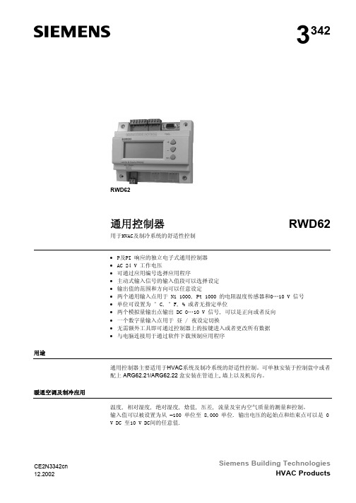
s3349RWD60RWD60通用控制器用于暖通空调与制冷系统的舒适度控制•带 P 或 PI 响应的独立电子通用控制器•工作电压为 AC 24 V•控制应用可以通过应用编号进行选择•可以选择有源输入范围•输出范围的限值和方向可以自由分配• 2 个通用输入端子,用于连接 Ni 1000、Pt 1000 温度传感器和 DC 0…10 V 信号•可以将单位设定为 °C、°F、%,或者不指定单位• 1 个 DC 0…10 V 调节信号输出,正作用或反作用•可以使用控制器上的操作按钮输入或更改所有数据,无需其他工具用途RWD60 通用控制器旨在供舒适度控制设备中的暖通空调和制冷系统使用。
该控制器可以安装于控制柜中,或者借助 ARG62.21/ARG62.22 外壳,安装于风管内、墙壁上和机房中。
RWD60 控制器是具备双输出功能的 RWD62 控制器的简化版本,包括了 RWD62控制器的所有特性和功能,但是价格更具竞争性。
RWD60 面向广阔的单回路、单输出市场。
暖通空调与制冷应用该控制器可对以下方面进行测量和控制:温度、相对湿度、绝对湿度、焓值、压差、体积式空气流量和室内空气质量。
输入范围的设置区间为−100 至 8,000。
输出电压的最小值和最大值可以是 DC 0…10 V 之间的任何数值。
CE2N3349_01zh2 / 10功能概览• 控制器独立的控制器,具备 1 个用于正作用或反作用的 DC 0…10 V 输出端子。
可调节参数,包括比例带和积分操作时间。
• 可选的辅助功能用于下列功能之一的通用输入端子 X2: − PI 限制器功能(绝对和相对) − 远程设定值功能 − 串级控制功能 − 设定值补偿− 冬季/夏季运行模式 − 最高优先级类型概览输入 输出 类型参考通用数字模拟数字2 0 1 0 RWD60名称 类型 用于墙面安装的小号保护外壳 ARG62.21 用于墙面安装的大号保护外壳 ARG62.22软件工具不适用设备组合以下西门子设备能够与 RWD60 通用控制器连接。
设备技术文档编号具备 LG-Ni 1000 感温元件的传感器 N17… 至 N19… 具备 Pt 1000 感温元件的传感器N1846具备 DC 0…10 V 测量信号的传感器 N17… 至 N19… 带有设定值调节装置的室内温度传感器 QAA25 或 QAA25/AP N1721…/N1728… 远程设定值调节装置 FZA21.11 和 FZA61.11 N19… 具备 DC 0…10 V 输入的风阀执行器 N46… 带有 DC 0…10 V 输入的阀门执行器 N45… 控制阀门N46… 用于当前阀门控制的信号转换器 SEM 61.4 N51… 多种信号转换器N34…如果第三方设备的输入端子和输出端子规格与 RWD60 控制器匹配,则该控制器还可以与第三方设备进行组合。
RWD62 控制器配备一款软件工具,以供控制器应用选择和参数调整。
对于 RWD60 控制器,该功能不适用。
附件软件工具功能RWD60 是一款独立的通用控制器,可以执行主要控制功能和辅助控制功能。
利用控制器操作按钮来输入相应配置并设定参数,即可定义各个模式。
RWD60 能够只针对 1 个序列进行编程,而且只有编号为 10…19 和 40…49 的应用能够使用:序列:Y1(反作用或正作用)反作用序列(应用编号:10…19)正作用序列(应用编号:40…49)通用输入端子 X1 用作主输入端子,用于连接 LG-Ni 1000 温度传感器、Pt 1000 温度传感器或者 DC 0…10 V 有源输入。
通用输入端子 X2 用作二次输入端子,用于连接 LG-Ni 1000 温度传感器、Pt 1000 温度传感器、有源/无源远程设定值传送器或者 DC 0…10 V 有源输入。
输出端子 Y1 既可以配置为反作用,也可以配置为正作用。
调节电压输出能够控制需要 DC 0…10 V 信号的设备。
具备温度控制装置的通风设备X1 室内温度Y1 供热、反作用或正作用可以从以下辅助功能中选择一项:• PI 限制器功能(绝对和相对)•远程设定值功能•串级控制功能•设定值补偿•冬季/夏季运行模式•最高优先级PI 控制的限制器功能支持对送风温度 (X2) 的最高值或最低值进行绝对(或相对)限制。
当温度值低于或高于设定限值时,限制功能开始工作,并且其优先级高于主设定值。
控制器类型主要功能通用输入端子 X1通用输入端子 X2模拟输出实例辅助功能PI 限制器功能3 / 10远程设定值传送器(FZA21.11、QAA25 或者QAA25/AP)与 X2 连接并进行相应配置,它支持调整设定值。
通过 DC 0...10 V 的可变电压来传入的有源测量值,对应的可调节范围是−100 (8000)通过 0…1000 Ω的可变电阻来传入的无源测量值,对应的可调节范围是−100 (8000)X2 送风温度传感器可以选择PI/PI 室内/送风温度串级控制功能。
在此情况下,虚拟 PI 室内温度控制器能够在设定限值范围内决定 PI 送风温度控制器的设定值。
最高优先级,制冷如果输入端子 X2 的值 (0…10 V) 大于制冷序列的输出总值,则 X2 输入值将被输出端子用作输出值。
即使控制器采用供热序列运行,该优先级仍然适用。
室内温度输入端子 X1 的设定值受室外温度输入端子 X2 的影响。
RWD60 的配置定义了 X2 端子对 X1 端子设定值的影响程度。
端子 X2 和 M 之间的数字开关或模拟输入可以用于执行冬季/夏季运行模式转换。
数字转换当触点闭合时,即选定夏季运行模式。
反作用输出(仅限 Y1)被设置为正作用(制冷)。
模拟转换当 X2 输入超过设定值时,即选定夏季运行模式。
反作用输出(仅限 Y1)被设置为正作用(制冷)。
远程设定值串级控制最高优先级设定值补偿冬季/夏季运行模式4 / 105 / 10机械设计 RWD60 通用控制器遵循 DIN 43 880 Gr. 1 要求。
当温度控制器安装在控制柜外面,如风管内、墙壁上和机房中时,保护性外壳可用于对其进行保护。
此外,保护性外壳还能避免控制器与接线端子等供电部件的意外接触。
RWD60 控制器可以卡入保护性外壳中。
线缆入口位于保护性外壳的顶部和底部。
外壳的正面留有开口,用于浏览 LCD 显示屏和操作按钮。
插件螺纹接线端子RWD60 控制器可通过上面的操作按钮进行操作,不需要其他工具。
LCD 能够显示以下常见操作信息: • 当前工作值(最高 4 位数) • 当前设定值 • 应用编号 • 输出电压值 • 控制序列图表 • 辅助输入值 •选定的辅助功能控制器具有 3 个操作按钮,能够执行以下功能: 选择按钮用于在调整数值时进行输入或保存。
操作按钮和用于查看和调整参数。
如需配置控制器,请参考控制器随附的说明。
外壳保护性外壳ARG62.21/ARG62.22端子操作和显示组件LCD操作按钮和配置6 / 10工程注意事项 RWD60 控制器仅适用于首页(粗体)和“应用”部分所描述的应用。
此外,请遵守本文“应用”部分和“技术参数”文档中的所有条件与限制。
带有该标识的内容列示了技术安全要求和限制。
请严格遵守此类警告要求,否则可能导致人身伤害和设备损坏。
安装须知RWD60 控制器可以按照以下方式安装: A 安装于顶帽式导轨(EN60715、35 × 7.5)上,该导轨长度至少为 120 mm B 利用 2 个螺丝进行墙面安装C使用标准组件进行正面安装,例如: 1 条 150 mm 的顶帽式导轨 2 个 50 mm 六角安装工具 垫圈和螺丝D安装于 ARG62.21/ARG62.22 保护性外壳中请遵守当地所有现行安装法规。
该控制器可以使用标准电缆。
但是,当安装环境电磁干扰 (EMI) 严重时,只能使用屏蔽电缆。
带RWD60 的工作电压为 AC 24 V 。
低压必须符合 EN 60730 所规定的安全超低电压 (SELV) 要求。
根据 EN 60742,采用具备双重绝缘功能的安全隔离变压器;这些变压器必须具备零宕机设计。
在一个系统中使用数个变压器时,接线端子 G0 必须能在电路中被识别为面向所有变压器的通用连接,以避免短路。
低电压接线端子连接 AC 24 V 以上的电压时,可能会损坏控制器或其他任何连接的设备。
此外,连接电压超过 AC 24 V 会威胁人身安全。
调试注意事项RWD60 控制器附有调试手册。
请在调试过程中注意以下条件和限制:• 必须使用标准应用,针对设备特定操作对控制器进行配置。
• 可以根据需要,对设备进行特定的微调(请参考调试手册)。
• 请确保控制器和其他设备连接 AC 24 V 的电源。
• 如果发生电源故障,将自动保存所输入的数值和设置。
用途电气安装EN60730N474最小直径为最大横截面为7 / 10G、G0 AC24V电源)M 接地端子 G0,用于数字输入、通用输入和模拟输出X1 信号输入(主输入 LS Ni 1000、Pt 1000 和 DC 0…10 V)X2 信号输入(辅助输入 LS Ni1000、Pt 1000、DC 0…10 V 和 0…1000 Ω或 DC 0…10 V 远程设定值)Y1 模拟输出连接图N1 RWD60控制器X1 主输入(当端子 X1 连接有源传感器时,需要端子 G)X2 辅助输入或远程设定值(当端子 X2 连接有源传感器时,需要端子 G)Y1 阀门执行器或风阀执行器8 / 109 / 10RWD603341m 0315020061.2ARG62.2110 / 10 © 2009(-2010) 西门子楼宇科技本文档如有更改,恕不另行通知。