西门子开关安装使用说明书2版
西门子2-口和3-口区域阀门产品说明说明书
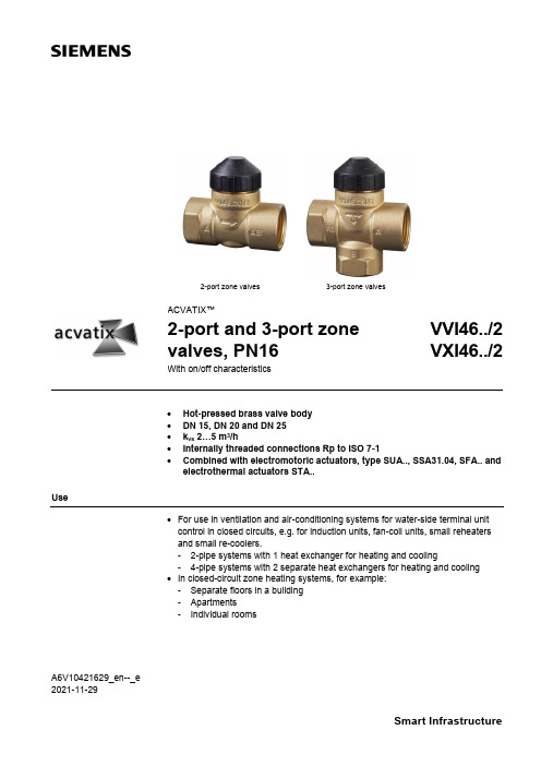
A6V10421629_en--_e 2021-11-292-port zone valves3-port zone valvesACVATIX™2-port and 3-port zone valves, PN16VVI46../2 VXI46../2With on/off characteristics• Hot-pressed brass valve body • DN 15, DN 20 and DN 25 • k vs 2…5 m 3/h• Internally threaded connections Rp to ISO 7-1•Combined with electromotoric actuators, type SUA.., SSA31.04, SFA.. and electrothermal actuators STA..Use• For use in ventilation and air-conditioning systems for water-side terminal unit control in closed circuits, e.g. for induction units, fan-coil units, small reheaters and small re-coolers.- 2-pipe systems with 1 heat exchanger for heating and cooling- 4-pipe systems with 2 separate heat exchangers for heating and cooling • In closed-circuit zone heating systems, for example: - Separate floors in a building - Apartments- Individual rooms2 / 10Type summaryTypeStock numberDNConnections PN classk vsA →AB [m 3/h]VVI46.15/2 S55249-V106 15 Internally threaded Rp162.15VVI46.20/2 S55249-V107 20 3.5 VVI46.25/2 S55249-V108 25 5.0TypeStock numberDNConnections PN classk vs 1) AB →A [m 3/h]k vs 1) AB →B [m 3/h] VXI46.15/2 S55249-V109 15 Internally threaded Rp162.151.5 VXI46.20/2 S55249-V110 20 3.52.5 VXI46.25/2 S55249-V111 25 5.03.5 VXI46.25T/2S55249-V112255.54.51)The k vs values in bypass B of the 3-port valves represent only 70 % of the k vs value in the straight-through control path AB → A. This compensates for the flow resistance of the heat exchanger or radiator, so keeping the overall flow rate100 as constant as possible.k vs = Nominal flow rate of cold water (5…30 °C) through the fully open valve (H 100), by a differentialpressure of 100 kPa (1 bar)OrderingWhen ordering, please specify the quantity, product name and number.The valves and actuators are delivered in separate packaging.The actuator SUA21/3, SSA31.04, SFA.. and STA.. must be ordered separately.The AL50 supporting ring (necessary for combination with SFA.. or SUA..) is included in the delivery of V..I46…See Revision number overview Revision number overview on page 10.ExampleProduct number Stock number Product nameQuantityVXI46.15/2S55249-V1093-port zone valve, PN16 DN15, kvs 2.15 1DeliveryRev. no.3 / 10Equipment combinations∆p max = Maximum permissible differential pressure across the valve’s control path, valid for the entireactuating range of the motorized valve (maximum recommended operating differential pressure) For noiseless operation, the value of 100 kPa should not be exceeded.∆p s = Maximum permissible differential pressure at which the motorized valve will close securelyagainst the pressure (close off pressure)1) ∆pmax(AB-B) is 50 kPa for VXI46.25T/21) SPST = single pole, single throw2)SSA31.04 could not be used with VVI46.25T/24832Z 01Technical design / mechanical design• Disc throttling element• Seat ring embedded in through-port• Seat machined into through-port and bypass• Reservoir for continuous lubrication of sealing rings •Return spring (to open position)Actuator overview4 / 10SizingExample:100 = 0.27 l/s ∆p v 100 = 9 kPak vs value required = 3.5 m 3/h∆p v 100= Differential pressure across the fully open valve and the valve's control path A → AB (2-port valves), AB → A (3-port diverting valves) by a volume flow100100= Volume flow through the fully open valve (H 100)∆p max= Maximum permissible differential pressure across the valve's control path, valid for theentire actuating range of the motorized valve100 kPa =1 bar≈10 mWC 1 m 3/h = 0.278 l/s water at 20 °C5 / 10Engineering notesRefer to Mounting notes and Commissioning notes . It is NOT allowed to put a shut off at the bypass port B.A strainer should be fitted upstream of the valve. This increases reliability.The direction of flow MUST be as indicated by the arrow, from A → AB.The direction of flow MUST be as indicated by the arrow, from AB → A and AB → B (diverting valves).RecommendationWarningWarning6 / 10Mounting notesThe specified direction of flow must be observed in all cases (refer to Engineering notes ).The mounting instructions 74 123 0114 0 B are enclosed with the packaging. The valve and actuator are easily assembled directly on site. There is no need for special tools or calibration.The AL501) supporting ring must be put into position before mounting the actuator SFA.. and SUA.. onto the valve.1) Included in deliveryOrientationAL50 supporting ringSIEMENSkvs5.0XYYMMAA 6V 10421629Z 017 / 10Commissioning notes In the straight-through control path A → AB, respectively AB → A the valve is opened by a return spring.The straight-through path can be closed manually with the manual adjustment button.With 3-port valves, this method can be used to open bypass B to 70 %. (exception: VXI46.25T/2)Maintenance notesV..I46../2 valves require no maintenance.When doing service work on the valve/actuator:• Deactivate the pump and turn off the power supply • Close the shutoff valves• Fully reduce the pressure in the piping system and allow pipes to completelycool downIf necessary, disconnect the electrical wires.Before putting the valve into operation again, make sure the manual knob or the actuator is correctly fitted.The stem sealing gland cannot be exchanged. In the case of leakage, the entire valve must be replaced. Contact your local office or branch.Disposal• Before disposal, the valve must be dismantled and separated into its various constituent materials.• Legislation may demand special handling of certain components, or it may be sensible from an ecological point of view. • Please observe current local legislation.WarrantyThe technical data given for these applications is valid only in conjunction with the Siemens actuators as detailed under Equipment combinations on page 2. Use with third-party actuators invalidates any warranty offered by Siemens Building Technologies HVAC Products.Manual adjustmentCautionStem sealing glandTechnical data8 / 109 / 10Dimensions 2-port valves 3-port valves VVI46../2VXI46../21)For seamless, round copper tubes according to DIN EN 1057Spare partsMultipack of 40 piecesRevision number overviewIssued by:Siemens Switzerland Ltd.Smart InfrastructureGlobal Headquarters Theilerstrasse 1aCH-6300 ZugSwitzerlandTel. +41 58-724 24 24/buildingtechnologies@ Siemens Switzerland Inc, 2014-2021 Delivery and technical specifications subject to change10 / 10。
安装说明书 - 西门子 - 440J-N 使能开关
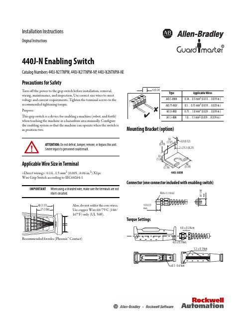
Installation InstructionsOriginal InstructionsR440J-N Enabling SwitchCatalog Numbers 440J-N21TNPM, 440J-N21TNPM-NP , 440J-N2NTNPM-NEPrecautions for SafetyT urn off the power to the grip switch before installation, removal, wiring, maintenance, and inspection. Use correct size wires to meet voltage and current requirements. Tighten the terminal screws to the recommended tightening torque.Purpose:This grip switch is a device for enabling a machine (robot, and forth) when teaching the machine in a hazardous area manually. Configure the enabling system so that the machine can operate when the switch is in position two.Applicable Wire Size in Terminal<Direct wiring>: 0.14…1.5 mm 2 (0.005…0.06 in.2) X1pc Wire Grip Switch according to IEC60204-1Recommended ferrules (Phoenix™ Contact)Mounting Bracket (option)Connector (one connector included with enabling switch)Torque SettingsATTENTION: Do not defeat, tamper, remove, or bypass this unit. Severe injury to personnel could result.IMPORTANTWhen using a stranded wire, make sure the terminals are notshort-circuited.Also, do not solder the core wires. Use copper Wire 60/75°C (140/167°F) only (UL 508).Type Applicable Wires AI0.5-8WH 0.34…0.5 mm 2 (0.013…0.019 in.)AI0.75-8GY 0.5…0.75 mm 2 (0.019…0.029 in.)AI1.0-8RD 0.75…1.0 mm 2 (0.029…0.039 in.)AI1.5-8BK1.0…1.5 mm 2(0.039…0.059 in.)440J-N Enabling SwitchExample of Wiring DiagramRealizing Safety Category 4Three Position Switch, Manual Reset, Monitored OutputThe external wiring is performed according to the protection measures against contact of dangerous potentials, such as double isolation or ground wire connection.One example of the circuit; safety relay module, MSR127RP manufactured by Allen-Bradley® Guardmaster®.Note: Use the monitoring device (safety relay module) providing it has the capacity to detect a cross short circuit. Wire the channels 1 and 2 of three-position switch as shown in the diagrams. Electromechanical switches must be wired with the control unit, that the requirements from DIN EN 775, DIN EN 60204-1, DIN EN 954-1, DIN EN 1088, and VDI 2854 are fulfilled. Two stage electromechanical switches are only allowed in combination with an E-stop unit.Contact OperationIMPORTANT Terminals 1-2, 3-4 and 5-6 (440J-N21TNPM and440J-21TNPM-NP) or 1-2, 3-4 (440J-N2NTNPM-NE) arepositive opening when the switch operates fromposition 2-3.Use contacts of terminals 1-2 and 3-4 for the output of theenabling system.The characteristics illustrate the performance when thecenter of the yellow button is pressed. Pressing the edgeactivates one of the two three-position switches inside earlierthan the other, and causes a delay in the operation of the gripswitch.2Rockwell Automation Publication 440J-IN001B-EN-P - June 2016Rockwell Automation Publication 440J-IN001B-EN-P - June 20163440J-N Enabling SwitchTechnical SpecificationsAttributeValueConforming to standards IEC 60947-5-1, EN 60947-5-1, GS-ET-22, JISC8201-5-1, UL 508 (UL Listed), CSA C22.2 No. 14 (cUL Listed)CertificationsCE Marked for all applicable directives, cULus, TÜV SUD Contact configuration 3-position switch Two contacts Auxiliary contacts 1 N.C.Emergency stop contacts 2 N.C.Push button contact 1 N.O.Rated operational voltage (Ue)30V 125V 250V R a t e d o p e r a t i o n a l c u r r e n t (l e )3-position switch440J-N21TNPM,440J-N21TNPM-NP ,440J-N2NTNPM-NEAC Resistive load AC 12- 3 A 1.5 A Inductive load AC 15- 1.5 A 0.75 A DC Resistive load DC 12 2 A 0.4 A 0.2 A Inductive load DC 13 1 A 0.22 A 0.1 A Auxiliary switch440J-N21TNPM,440J-N21TNPM-NPAC Resistive load AC 12- 2 A 1 A Inductive load AC 15- 1 A 0.5 A DC Resistive load DC 12 2 A 0.4 A 0.2 A Inductive load DC 13 1 A 0.22 A 0.1 A Emergency s top switch440J-N2NTNPM-NEACResistive load AC 12---Inductive load AC 1--0.5 A DC Resistive load DC 12---Inductive load DC 13--0.1 A Push button switch440J-N21TNPM-NPACResistive load AC 12 1.5 A 0.5 A -Inductive load AC 15 1 A 0.3 A -DCResistive load DC 12 1 A 0.2 A -Inductive load DC 130.7 A0.1 A-Minimum current 3V, 5 mA AC/DCShort-circuit protection device 250V, 10 A fuse (IEC 60127-1)Thermal current (l th )3 A Rated insulation voltage(Ui) 250V (push button switch: 125V)Rated impulse withstand voltage (Uimp) 2500V (except push button switch)Pollution degree 3Operating forcePosition 2 Position 315 N approximate 50 N maximum Actuation frequency, maximum 1200 operations per hourProtection IP66: 440J-N21TNPM; IP65: 440J-N21TNPM-NP , 440J-N2NTNPM-NE Conduit entry 1 x M20 (enclosed within the switch)Applicable cable diameter 7…13 mm (0.27…0.51 in.)Insulation resistance 100 M Ohm minimum Contact resistance100 M Ohm maximum Temperature rise - contact [C (F)]30 (86) maximum Temperature rise - terminal [C (F)]30 (86) maximum Actuator strength 500 N minimumWeight [g (oz)]210 g (7.4 oz): 440J-N21TNPM; 220 g (7.76 oz): 440J-N21TNPM-NP; 250 g (8.82 oz): 440J-N2NTNPM-NE ColorBlack/gray Case material of switch body PA66Rubber boot material NBR/PVCOperating temperature [C (F)]-10…60° (14…140°)Mechanical life - grip switch Position 1 - 2 - 1: 1,000,000 operations; Position 1 - 2 - 3 - 1: 100,000 operations Electrical life - grip switch 100,000 operations Electrical life - emergency stop 100,000 operations Electrical life - push button100,000 operationsIMPORTANT The operating force of the grip switch depends on the ambient temperature.Allen-Bradley, Rockwell Automation, Rockwell Software, and Guardmaster are trademarks of Rockwell Automation, Inc.Trademarks not belonging to Rockwell Automation are property of their respective companies.Rock w ell Otomasyon Ticaret A .Ş., Kar Plaza İş Merkezi E B lok Kat:6 34752 İçerenköy, İstanbul, T el: +90 (216) 5698400Rockwell Automation maintains current product environmental information on its website at/rockwellautomation/about-us/sustainability-ethics/product-environmental-compliance.page .Publication 440J-IN001B-EN-P - June 201609279 Ver 04Supersedes Publication 440J-IN001A-EN-P - February 2012Copyright © 2016 Rockwell Automation, Inc. All rights reserved. Printed in the U.S.A.MaintenanceEvery WeekChec k the correct operation of the switching circuit. Also chec k for signs of abuse or tampering. Inspect the switch casing for damage. Of particular importance is damage, which causes loss of sealing at the lid or conduit entry.At Least Every Six MonthsIsolate the power. Remove the lid. Inspect all terminals for tightness. Clean out any accumulation of fine dirt, and so forth. Chec k for any sign of wear or damage, for example, rubber boot wear or contact oxidization, and replace if apparent. Replace cover and tighten screws to specified settings. Reinstate the power and chec k for correct operation. Reapply tamper evident varnish or similar compound to mountings.RepairIf there is any malfunction or damage, no attempts at repair are made. The unit has to be replaced before machine operation is allowed.DO NOT DISMANTLE THE UNIT.Precautions for OperationDo not apply excessive shoc k to the switch. Wire the switch correctly after reading this instruction sheet. T o help ensure safety of the control system, connect each pair of contacts of the three-position switch (terminal number 1-2 and 3-4) to a discrepancy detection circuit such as a safety relay module (ISO 13849-1/EN 954-1).When wiring, prevent dust, water, or oil from entering the grip switch. Do not tie the grip switch around the button with tape or string to k eep the switch in position two. Otherwise, the original function of the switch is not used, which poses a great ris k of danger. If used in wet locations, this device must be used with cable suitable for wet locations.EU Declaration of ConformityThe Declaration of Conformity declares that the products that are shown in this document conform with the relevant requirements of the Low Voltage Directive (2014/35/EU).These products also conform to EN 60947-5-1, EN 60947-5-8, GS-ET-22, UL 508, CSA C22.2 No. 14 and have Third-Party Approval. Conforming with the European Machinery Directive depends on the application of the product.For a comprehensive certificate, visit: /safety.Additional ResourcesThese documents contain additional information concerning related products from Rockwell Automation®.You can view or download publications at /global/literature-library/overview.page . To order paper copies of technical documentation, contact your local Allen-Bradley distributor or Rockwell Automation sales representative.ResourceDescriptionIndustrial Automation Wiring and Grounding Guidelines, publication 1770-4.1Provides general guidelines for installing a Rockwell Automation industrial system.Product Certifications website,/global/certification /overview.pageProvides declarations of conformity, certificates, and other certification details.。
西门子Vector系列集合操作开关说明书

Vector® seriesGroup-operated switches manual and motorized/disconnectswitchesOverviewDesigned for superior reliability and load-breaking performance, the Vector series of group-operated air-break switches includes 15/25 kV and 38 kV versions. Manufactured as a true unitized switch, the Vector series is completely factory assembled and adjusted to eliminate the need for tuning in the field. Utilizing Siemens innovative Saf-T-Gap interrupters for dependable loadinterruption, bolt-on style interrupters are supplied as standard with plug-in styleinterrupters available as an option for rapid change-out using a shotgun stick.VectorOperational reliability is enhanced byenclosing the operating mechanism inside the switch base for superior weather protection. Ease-of-operation is assisted with the use of environmentally sealed, oil impregnated sintered bronze bearings supporting a balanced-force operating mechanism. Galvanized steel, fiberglass, and aluminum tubular bases are available.2OverviewInstallation is made simple with the factory-installed “single-point lift bracket.” Provisions for dead-ending all three conductors is standard (on most models) along with the “pole hugger” design for improved aesthetics.All Vector series switches are available in pipe-operated versions, hookstick-operated gang versions and motorized versions with SCADA control.3Enclosed operating mechanismOperational reliability is assured by enclosing the operating mechanism inside the switch base to shield it from the environment. Two interposing rods balance the forces acting on the rotating insulator shafts to provide dependable push-pull switching.14123455DetailsHookstick-operated gangThe HOG – horizontalThe HOG – vertical* Weight does not include operating pipe.* Weight does not include operating pipe.6Pipe operatedDetailsPipe operated – horizontalPipe operated – vertical (cable riser style)* Weight does not include operating pipe.* Weight does not include operating pipe.7DetailsHookstick-operated gangThe HOG – symmetricalThe HOG – inverted* Weight does not include operating pipe.* Weight does not include operating pipe.* Weight does not include operating pipe.8Pipe operatedDetailsPipe operated – symmetricalPipe operated – inverted* Weight does not include operating pipe.* Weight does not include operating pipe.* Weight does not include operating pipe.9ConfigurationsThe Vector ® series is available in pipe-operated and hookstick-operated versions. For additional options or configurations, please contact yourSiemens representative.1410AutomationVersatility is key when it comes to operating a motorized group-operatedairbreak switch locally or remotely. Combining the field proven reliability of themanually operated Vector series with engineered controls, the Auto-Pak Vector(APV) enables applications such as auto-transfer and auto-sectionalizing.Optional voltage and current sensors can be mounted directly to the switch unitto provide a cost-effective line monitoring and fault detection solution.11Vector numbering systemPosition:12345*A B1C*Consult factory for custom configurations.12DetailsVector ratings:• 900/1,200 A continuous current• 630 A loadbreak• Momentarycurrent loadbreak• 25,000 A three second• 20,000 A one-time symmetricalfault close in• 15,000 A three-time symmetricalfault close in.Standard features:• Silver-to-silver hinge andjaw contacts• Dead-end bracket supplied asstandard (not available for verticalriser model)• E nclosed balanced bearingoperating mechanism• Pole-hugger operating shaft forimproved installation appearance• Four 7’ pipe sections, handle andlocking assembly and necessarycouplings and guides• Single-point lift bracket• All components packaged inone crate• 630 A bolt-on Saf-T-Gapinterrupters. Plug-in style availableas an option.• Copper-bronze live parts• Tinned terminal pads.3EK4 (APS) surge arrester3EK8 (APS) surge arrester131415Siemens Industry, Inc.99 Bolton Sullivan DriveHeber Springs, Arkansas 72543For more information, including service or parts,please contact our Customer Support Center.Phone: 1-800-333-7421/disconnectswitchesOrder No.: E50001-F630-A167-01-76USPrinted in U.S.A.© 2019 Siemens Industry, Inc.The technical data presented in this document is based on an actual case or on as designed parameters, and therefore should not be relied upon for any specific application and does not constitute a performance guarantee for any projects. Actual results are dependent on variable conditions. Accordingly, Siemens does not make representations, warranties, or assurances as to the accuracy, currency or completeness of the content contained herein. If requested, we will provide specific technical data or specifications with respect to any customer‘s particular applications. Our company is constantly involved in engineering and development. For that reason, we reserve the right to modify, at any time, the technology and product specifications contained herein.。
上海西门子开关 产品介绍 说明书

■ 上海西门子开关有限公司2的严格管理不仅贯穿于内部生产的各个流程,同时延伸至对供应商的日年在闵行经年底公司二期厂房扩建工程的竣平方米,体现了西门子根植于中国、长期服务于中国客户的信心和承诺。
2004年研发中心作为西门子输配电全球研发中心的组成部分,可同步共享西门子最新的技术和资源。
通过预测客户的需求,开发质量稳定可靠的创新型产品和为客户度身定制方案,使客户的业务增值。
一支反应迅速、装备精良、经验丰富的售后服务队伍和遍布全国的服务网点构成了公司一套高效的现场服务应对系统,负责指导产品现场安装和操作,并承诺在最短时间内对紧急情况作出应对,将客户的断电年位列上海市年被上海市电器行业协会评为行业名优产品。
公司因其良好的商业信誉被评为“守合同重信而被电气时代以及专3AH3及面向全球同步发售所有产品均在西安高压电器研究所通过型式试验,确保产品的运行安全和操作人员的人身安全。
目 录ContentsSiemens Switchgear Ltd., Shanghai (SSLS) is a joint venture of Siemens Ltd., China (SLC) and Shanghai Power Transmission & Distribution Company, holding the manufacturing license to apply the latest tech-nology of Siemens vacuum circuit-breaker and medium voltage switchgear in P. R. China.Since established in 1993, relying on Siemens powerful resources and internal boundless cooperation, SSLS has provided reliable products, first-class service and innovative solutions for more than two thousand key projects both for domestic and overseas. SSLS has established a good reputation and leading position in China due to its large contribu-tion to the technique innovation and development of local switchgear industry.SSLS is a market oriented company with commitment to customers’satisfaction and to fulfill the demands for the medium voltage switchgear, with high quality and excellent reliability, by means of dynamically intro-ducing and constantly developing the applicable technique and prod-ucts to the local market. Customer’s success is our first priority. We pledge to provide the most value-added product and service, promise on-time delivery, and establish solid business partner relationship with customers, in result to create the maximum value for our customers.SSLS began to implement the customer-oriented quality management early in1996, and established a comprehensive quality management system in 2004 integrated with ISO9001, ISO14001 and OHSAS18001. The company utilizes the highly sophisticated machines and testing fa-cilities in production process. The high qualification of operators along with continuous in process quality control guarantee our well established and high quality standards at all times. The strict quality control is not only carried out throughout entire production processes, but also ex-tended to the daily management of our suppliers. We take environment protection as our social responsibility; meanwhile closely look after employees’ occupational safety and health.To meet the growing marketing demands, a modern factory was built up in Minhang Economic & Technological Development Zone in 2004. With the completion of second phase expansion at the end of 2006, the land plot increased to 50000sqm and shop floor to 23000sqm, which em-bodies Siemens’ commitment to root in China and serve long-term for Chinese customers.According to company’s strategy to create more competence and shorter time-to-market, SSLS R&D center was established in 2004. R&D cen-ter closely integrates into the Siemens PTD global R&D network, could share the latest Siemens technique and resources in-phase. By pre-dicting the market needs, SSLS fosters R&D in developing reliable and innovative products and tailored solutions to add value for customer’s business.Siemens switchgear has an effective system of on-site servicing from a quick-respondent, well-equipped and rich experienced field service team and a network setup all over China. The team is responsible for the guidance of on-site installation and operational safety, commit to re-spond to emergency calls within the shortest possible time and to mini-mize down time.SSLS was ranged as the Top 500 Revenue of Industrial Companies in Shanghai 7 years in row since 2000. The products won the title of Shang-hai Reputed Product 4 years in row since 2003. The company was awarded as “Good Credit Enterprise” due to its high commercial credit, and won the title of “Top 10 Fast-growing Companies in China Electric Industry” in 2006 due to over 30% increase of sales revenue continu-ously over the past three years.PRODUCT INTRODUCTIONSSLS provides air insulated Switchgear rated from 7.2 to 24kV with type 8BK20, 8BK30, 8BK40 and specially designed for Chinese market in 2007 NXAIR S, and vacuum circuit breakers type 3AH3, 3AH5, 3AH2-EP as well as SION, the latest generation of Siemens VCB synchro-nously selling world wide.All products are type tested in XIHARI to ensure the safety of personnel and operation.公司简介Company Introduction■产品介绍3■ 上海西门子开关有限公司4● Draw-out section and access door fully inte-grated interlock system.● Safe and easy draw-out section movementbehind closed cubicle door.● Easy draw-out section transfer or exchange,using central service truck, independent of floor quality.● Earthed metal partitions and shutters.● Connection of HV cables is available from front or rear part of the panel optionally.● Back-to-back or face-to-face designs available for double bus-bar design.●Reinforced insulation which fulfills Chinese system and local climate.●Direct line-up with 8BK30 Vacuum ContactorSwitchgear.● 可移开部分与柜门之间有可靠的联锁● 前门关闭后,能够很安全而且容易地移动可移开部分● 先进的中置式结构,使用专门的小车能够方便地搬运或更换可移开部分,不受现场地面平整度的限制● 金属隔板与活门均接地● 根据用户需要,可由前门或开关柜的后部进行电缆接线● 开关柜可以面对面布置,也可以背靠背布置(双母线回路)●加强了绝缘,更适合中国电力系统和气候● 可直接与8BK30型开关柜(F - C 回路)联接供电典型客户上海供电局北京供电局兰溪电厂秦皇岛港口宁波小港纸业兰州石化TYPICAL CUSTOMER Shanghai PSBBeijing PSBLanxi Power PlantQinghuangdao HarborNingbo Xiaogang Paper MillLanzhou Petro 产品特点SPECIFIC FEATURES 电气技术数据 ELECTRICAL DATA (MAXIMUM VALUES )8BK20 Switchgear with Draw-Out Circuit-Breakers, Air-Insulated, Metal Clad8BK20型金属封闭/铠装可移开式空气绝缘断路器柜■ 产品介绍5● Draw-out section and door integrated in the inter-lock system.● Minimal space requirement.● Vacuum contactor and HVHRC fuses on draw-outsection. Vacuum contactor is able to operate fre-quently due to its long mechanic life-1 millionoperations.● Draw-out section easily to move inside the cubicle.● Cable connection in front of cubicle.● Directly line-up with circuit-breaker panel of type 8BK20.● Special wheels on bottom of draw-out section provide an easy movement during in and out the cubicle.● Reinforced insulation to meet Chinese system andlocal climate.● 可移开部分与室门之间装有可靠的联锁装置● 占用空间少● 可移开部分装有真空接触器和高压限流熔断器。
西门子断路器说明书

真空断路器 3AH3 7.2KV-36KV(2)真空灭弧室图2/5给出了用于3AH3真空断路器中的真空灭弧室的基本结构的剖视图。
根据型号,真空灭弧室(30.)被固定在上支架(20.)。
电弧室(33.)安装在两个陶瓷绝缘子(32.)之间。
静触片(31.)被直接连接在柜上。
动触片(36.)被安装固定在导轨(35.)中的接线端子螺栓(36.1)上。
金属波纹管形成到灭弧室的真空密封连接。
图2/5真空灭弧室安装在3AH3真空断路器中的真空灭弧室被定型核准符合联邦德国的X 射线规则。
它们符合1987年1月8号(联邦法公报第144页)§8规定的X 射线规则的要求和附件Ⅲ第5部分规定的额定瞬间交流电压符合DIN VDE/IDE 标准。
补充说明基本型号的真空断路器包括:带有机械和电气反转的电气操作机械(储能电动机)(M1)合闸线圈(Y9)脱扣分路(Y1)64头带金属孔眼套筒的低压插塞式连接器(X0)辅助开关,6常开+6常闭(S1)“合闸线圈储能”信号的位置开关(S41,S42)断路器分闸信号,信号复位开关(S6,S7)操作次数计数器防止误合闸的闭锁每个3AH3真空断路器也可以装有下面一些设备:接线板(X0)扩展的辅助开关,12常开+12常闭(S1)脱扣分路3AX1101 (Y2)电流互感器操作脱扣3AX1102 (Y4,Y5)电流互感器操作脱扣3AX1104(0.1WS)(Y6)低电压脱扣3AX1103 (Y7)手动电气合闸机械闭锁除标准的脱扣分路外,3AH3真空断路器也可以最多安装两个3AX11型脱扣分路。
在一览表HG11中声明了容许的辅助设备组合和特定的型号。
安装在配电柜或手车上安装供应的3AH3真空断路器是敞开的,可以看到“和闸弹簧脱扣”指示。
在安装3AH3真空断路器之前,先移走运输设备(制动器和定位器)。
根据提供的图纸,面向松开的相间隔板安装。
在将3AH3真空断路器安装进柜中或手车上之前,检查它的额定铭牌数据(避免混乱),比较交货单指明的额定电压与本地可供的电源电压。
西门子操作手册

目录1 安全信息 (1)术语定义 (1)前言 (1)2定位器的供货范围 (2)3组装…………………………………………………………………概述…………………………………………………………………定位器在潮湿环境中的使用……………………………………定位器在易受到强加速作用力或震动场合的使用……………直行程执行机构的连接附件………………………………………组装顺序……………………………………………………………角行程执行机构的连接附件………………………………………组装顺序………………………………………………………………4可选附件的安装……………………………………………………5电气连接……………………………………………………………6气动连接……………………………………………………………注入仪表空气开关………………………………………………..限流器………………………………………………………………7调试(见散页“操作—简要说明”)………………………………直行程执行机构调试准备…………………………………………直行程执行机构的自动初始化…………………………………直行程执行机构的手动初始化…………………………………角行程执行机构调试准备…………………………………………角行程执行机构的自动初始化…………………………………角行程执行机构的手动初始化…………………………………故障校正……………………………………阀门定位器的简明操作指南………………..附录一………………………………………………………………………附录二………………………………………………………………………1 安全信息1.2 前言本操作说明描述了定位器组装、连接、调试的基本步骤,不能取代SIPART PS2电气阀门定位器的操作手册,操作手册中包含了组装、功能、操作的详细信息。
无危险使用关于安全方面,定位器出厂时已达到完美状态,如果要保持此状态,用户必须要遵守本操作说明中安全提示。
西门子开关安装使用说明书
KYN28A-12(3AH5、3AH3)户内高压真空断路器安装使用说明书广东珠江开关有限公司二OO六年六月目录1概述1.1总则 (2)1.2使用条件 (2)1.3技术参数 (3)1.4机械参数 (3)1.53AH5外形尺寸 (4)1.63AH3外形尺寸 (5)2结构与功能2.1断路器总体结构 (6)2.2断路器内部接线原理图…………………………….7~8 3调试和操作3.1准备工作 (9)3.2机构储能操作 (9)3.3合闸、分闸 (9)3.4与柜体配合过程操作 (10)4储运4.1运输 (10)4.2仓储 (10)5维修 (10)6随机文件 (10)7订货须知 (11)1概述1.1总则3AH5和3AH3户内高压真空断路器是三相交流50Hz,额定电压12kV户内高压开关设备。
断路器符合IEC56、IEC694、BS531以及DINVDE0670的所有条款,而且还满足中国标准GB1984《交流高压断路器》和DL403(绝缘部分),并具有可靠的联锁功能。
重要说明:——主要零配件由西门子公司提供;——本公司是西门子公司授权制造商;——本公司与西门子公司进行技术合作,生产3AH开关;——产品受到西门子公司的质量监督和控制。
1.2使用条件1.2.1正常条件环境温度环境湿度最高温度+40℃日平均相对湿度95%≤最底温度-15℃月平均相对湿度90%≤日平均值不大于+35℃断路器装置地点的海拔高度最高可达1000m。
1.2.2特殊使用条件顾客若偏离正常使用条件可与制造厂家协商制造1.3技术参数——(表1)1.4机械参数——(表2)正视图——(图1)正视图——(图3)2结构与功能2.1断路器总体结构——(图5)1.航空插座2.分闸按钮3.分合指示4.手柄储能孔5.合闸按钮6.储能指示7. 计数器8. 联锁装置9.绝缘子10.真空灭弧室11.导电触臂12.相间隔板2.2 断路器内部接线原理图运行位置试验位置1~58 58针孔的航空插座 MO 弹簧机构的储能电机 K1 机构内部防跳继电器 Y1 分闸脱扣器 Y9 合闸脱扣器 S1 辅助开关 S21、S22、S3、S41 储能位置辅助开关 S8 试验位置辅助开关 S9 工作位置辅助开关3AH5断路器内部接线原理图——(图6)试验位置运行位置A1~D16 64针孔的航空插座 MO 弹簧机构的储能电机 K1 机构内部防跳继电器 Y1 分闸脱扣器 Y9 合闸脱扣器 S1 辅助开关 S21、S22、S3、S41 储能位置辅助开关S8 试验位置辅助开关 S9 工作位置辅助开关 Y0 闭锁电磁铁 S10 柜前合闸辅助开关 S11 柜体间联锁辅助开关3AH3断路器内部接线原理图——(图7)3调试和操作调试和操作中的各项工作应由受过专门训练、详细了解本装置开关设备性能的人员进行,工作中必须考虑相应的保护和预防措施。
西门子 通用控制器RLU2. 说明书
CE1N3101en Siemens Building Technologies3101Synco™ 200通用控制器RLU2...• 带有预置的标准应用• 自由编程的控制器,以适用于相关型号的设备 • P-, PI, 或 PID 模式 • 菜单驱动操作用途用于从基本到复杂的通风、空调和制冷设备。
通用控制器用于处理以下控制变量:温度、相对/绝对湿度、压力/压力差、气流、室内空气质量和焓值。
功能 • 通过状态输入选择运行模式: 舒适、经济、保护 • 显示当前运行模式 (舒适、经济、保护)• 带有各自的顺序控制器: 独立可调节的加热和冷却设定点(或最大和最小设定点)用于舒适和经济模式• 通过室内操作单元或设定点再调节器(无源)预定义室温设定点• 用各种顺序控制器: 用远程设定点调节器(有源或无源)预定义设定点 • 带夏季和/或冬季补偿的室温设定点• 用各种顺序控制器: 设定点偏移取决于传感器信号、可选的起点和终点 通用输入:• 不同测量值的无源或有源模拟输入信号 (°C, %, ---) • 数字输入信号(无电压干节点)操作模式 设定点通用输入3101P 032/26• 用于两个供热顺序(反向作用)和两个冷却顺序(正向作用)的通用控制器(顺序控制器) 可以作为提供P-, PI 或PID 模式的控制器,也可以作为差动控制器 • 控制器可以配置为室内/送风气温串级控制器,同时限制送风温度。
• 各顺序可指定为调节输出控制(调节输出、步进开关、混风风门、热回收设备)和泵。
2个顺序可同时作用于相同的调节输出控制(如优先冷却/除湿)• 一般限制功能 (每个顺序控制器以PI 模式形成最大/最小功能 ),可用于绝对限制(如送风气温或送风湿度),也可用于相对温度限制(如室内/送风气温温差)。
限制对所有的顺序都有所用。
当冷却打开(如用直接膨胀制冷盘管)时,对较低的设定点可以设置下限。
• 每个顺序控制器用PI 模式的顺序控制功能,可以定义为下限或上限。
西门子开关PT柜电压继电器说明书MRU3_2_cn
4 工作原理 4.1 模拟回路 4.2 数字回路 4.3 星形或三角形接线法选择 4.4 电压监视 4.4.1 单相/三相监视 4.4.2 电压不平衡保护原理 4.4.3 测量原理 4.4.4 对称电压系统的负序系统 4.4.5 电压不平衡系统 4.4.6 零序系统 5 操作和整定 5.1 显示 5.2 整定步骤 5.3 系统参数 5.3.1 一次量(Uprim/Usec)显示剩余电压 UE 5.3.2 D/Y – 转换 5.3.3 额定电压的设置 5.3.4 激活储存的显示 5.3.5 参数组转换开关/故障记录仪的外部触 发器 5.4 保护参数 5.4.1 单相或三相 U</U>-跳闸 5.4.2 过压和欠压监视的参数整定 5.4.3 正序系统电压 (U1<, U1>) 5.4.4 负序系统过压 (U2>) 5.4.5 零序系统过压 (U0>) 5.4.6 从属地址的调节 5.4.7 波特率的整定 (仅适用于 Modbus协议) 5.4.8 奇偶校验的整定 (仅适用于 Modbus协议) 5.5 故障记录仪参数 5.5.1 故障记录仪的调节
或
闭锁可通过配置模式自由选择(参阅第5.9节)。 输入端 D8 是闭锁与外部复位的接地(L- 或 N)。闭锁 功能在辅助电压从 D8/E8 端子断开后立即恢复。 以上功能在施加电源电压后闭合 2 秒钟。 3.1.3 外部复位输入 独立于记录时间,整个储存空间可被分成数个干扰 事件,每个带较短的记录时间。此外,故障记录仪 的清除功能也会受影响。 不可覆盖 如选择 2、4 或 8 个记录存储,整个储存空间就会 分成相应数量的储存块。当超过故障事件的最大记 录数量时,故障记录仪会阻止更多的记录,防止已 存数据被覆盖。在读取或删除数据后,记录仪将继 续记录。 的 采样 频 率是 1.25 ms ( 50 Hz) 和 1.041 ms ( 60 Hz),并被储存在循环缓冲器内。 存储分区
西门子定位器使用说明书2
SIPART PS2 定位器采用适当的安装组件固定到直行程 或角行程执行机构上,执行机构的直线或转角位移通过 安装的组件检测并由一个刚性连接的导电塑料电位器转 换,装在直行程执行机构上的组件检测得到的角度误差 被自动地校正.
微处理器根据偏差(给定值 W 与位置反馈信号 X)的大 小和方向输出一个电控指令给压电阀。
图.5 分离安装的执行机构行程检测系统和控制单元
3
SITRANS PS2 智能电气阀门定位器
SIPART PS2,SIPART PS2 PA,SIPART PS2 EEx d 和 SIPART PS2 EEx d PA
工作方式
SIPART PS2 型智能电气阀门定位器的工作原理与传统 定位器完全不同。
三种防爆产品型式
基型产品有防爆等级为 EEx ia/ib 的本安型产品或用于 2 区的非本安型产品(见本安型产品技术数据)。
SIPART PS2 EEx d 隔爆型产品允许用在非本安应用的 1 区(具有 FM 认定证书也可应用在 0 区,见技术数据)。 这时允许使用全部可选择的模板而无需更换标牌。
通过 SIMATIC PDM 软件进行操作和监控
SIPART PS2 的工作方式及其集成的附加功能为用户在定 位器安装和操作使用上提供相当多的好处:
• 安装简易、高度自动化的调校,意味着节省时间,并 确保可靠运行。
• 一个在线自适应程序意味着即使在不利的工况条件下 也能实现非常高的质量控制。
• SIPART PS2 只有很少的可动部件,不受振动影响。
g直行程和角行程执行机构采用同一类型的阀门定位器g三个按键和双行lcd显示可实现简捷的操作和编程g具有零位和行程范围自动调整的功能g手动操作时无需另外的设备g具有可选的或可编程的输出特性g具有自诊断功能见第4页g耗气量极小g设定值和控制变量极限值可进行选择g可编程设置阀门quot
- 1、下载文档前请自行甄别文档内容的完整性,平台不提供额外的编辑、内容补充、找答案等附加服务。
- 2、"仅部分预览"的文档,不可在线预览部分如存在完整性等问题,可反馈申请退款(可完整预览的文档不适用该条件!)。
- 3、如文档侵犯您的权益,请联系客服反馈,我们会尽快为您处理(人工客服工作时间:9:00-18:30)。
KYN28A-12(3AH5、3AH3)户内高压真空断路器
安装使用说明书
广东珠江开关有限公司
二OO六年六月
目录
1概述
1.1总则 (2)
1.2使用条件 (2)
1.3技术参数 (3)
1.4机械参数 (3)
1.53AH5外形尺寸 (4)
1.63AH3外形尺寸 (5)
2结构与功能
2.1断路器总体结构 (6)
2.2断路器内部接线原理图………………………………………….7~8 3调试和操作
3.1准备工作 (9)
3.2机构储能操作 (9)
3.3合闸、分闸操作 (9)
3.4与柜体配合过程操作 (9)
4储运
4.1运输 (9)
4.2仓储 (10)
5维修 (10)
6随机文件 (10)
7订货须知 (10)
.
1概述
1.1总则
3AH5和3AH3户内高压真空断路器是三相交流50Hz,额定电压12kV 户内高压开关设备。
断路器符合IEC56、IEC694、BS531以及DINVDE0670的所有条款,而且还满足中国标准GB1984《交流高压断路器》和DL403(绝缘部分),并具有可靠的联锁功能。
重要说明:
——主要零配件由西门子公司提供;
——本公司是西门子公司授权制造商;
——本公司与西门子公司进行技术合作,生产3AH开关;
——产品受到西门子公司的质量监督和控制。
1.2使用条件
1.2.1正常条件
环境温度环境湿度
最高温度+40℃日平均相对湿度95%≤
最底温度-15℃月平均相对湿度90%≤
日平均值不大于+35℃
断路器装置地点的海拔高度最高可达1000m。
1.2.2特殊使用条件
顾客若偏离正常使用条件可与制造厂家协商制造。
1.4机械参数——(表2)
图1——正视图
图3——正视图
2结构与功能
2.1断路器总体结构(图5)
1.航空插座
2.分闸按钮
3.分合指示
4.手柄储能孔
5.合闸按钮
6.储能指示
7. 计数器
8. 联锁装置
9.绝缘子10.真空灭弧室11.导电触臂12.相间隔板
13.绝缘挡板14.推进板15.底盘车16.框架
2.2 断路器内部接线原理图(图6、图7)
运行位置
试验位置
1~58 58针孔的航空插座 MO 弹簧机构的储能电机 K1 机构内部防跳继电器 Y1 分闸脱扣器 Y9 合闸脱扣器 S1 辅助开关 S21、S22、S3、S41 储能位置辅助开关 S8 试验位置辅助开关 S9 工作位置辅助开关
图6——3AH5断路器内部接线原理图
试验位置
运行位置
A1~D16 64针孔的航空插座 MO 弹簧机构的储能电机 K1 机构内部防跳继电器 Y1 分闸脱扣器 Y9 合闸脱扣器 S1 辅助开关 S21、S22、S3、S41 储能位置辅助开关
S8 试验位置辅助开关 S9 工作位置辅助开关 Y0 闭锁电磁铁 S10 柜前合闸辅助开关 S11 柜体间联锁辅助开关
图7——3AH3断路器内部接线原理图
3调试和操作
调试和操作中的各项工作应由受过专门训练、详细了解本装置开关设备性能的人员进行,工作中必须考虑相应的保护和预防措施。
3.1准备工作
a.检查断路器有无损坏或任何其他损坏的环境,若有此现象,应恢复
其正常的工作条件。
b.检查一、二次回路连线和接地体的连接状况。
c.用手柄手动储能,并进行手动合、分闸操作。
3.2机构储能操作
a.手动储能:用储能手柄伸入机构的储能孔,顺时针转动手柄(约
40~50圈),至‘已储能’指示(图8)出现。
b.电动储能:使电机通电自动进行储能,储能到位后电机自动切断。
未储能已储能
图8——储能状态指示
3.3合闸、分闸操作
合闸:操作断路器合闸按钮和电气控制元件。
分闸:操作断路器分闸按钮或电气控制元件。
每次分闸操作中断路器计数器自动进一数,从面板观察窗观察计数
器的位置。
3.4与柜体配合过程操作
a、3AH5和3AH3系列户内高压真空断路器通过转运小车推入柜中。
断路器底盘锁板与柜体进入配合状态,此时断路器进到试验/隔离位置;
在二次操作电源得电情况下可以进行分合闸操作。
b、只能在工作位置和试验位置才能进行分、合闸的操作,而且合闸
之后不能移动断路器手车。
4储运
4.1运输
相应的保护,在操动机构外壳两侧板上各有一个起吊孔,作为起重断路器之用。
4.2仓储
真空断路器在使用之前必须储存在干燥、无尘埃及通风良好的场所。
同时断路器必须处于分闸状态,而且机构处于未储能状态。
5维修
为使断路器可靠地运行,所需进行的维修工作的间隔时间和维修范围将取决于工作环境影响、操作次数、运行时间以及开断短路电流次数等诸多因素。
维修工作必须有通过培训、熟悉所装置的开关设备特性的人员担任。
顾客可以打开面板对机构进行一些适当的维护(包括润滑)。
禁止对断路器进行违规操作。
6随机文件
a)产品合格证
b)出厂检验报告
c)安装使用说明书
d)装箱单
7订货须知
顾客在订货时应注明
a)断路器名称、型号、规格及订货数量;
b)断路器额定电压、额定电流及额定短路开断电流;
c)可选元件方案;
d)额定操作电压;
e)备品、备件的名称及数量;
f)顾客若有其它特殊要求,可在订货时说明。
编制:校对:批准:日期:
10。