西门子塑壳断路器脱扣器整定说明
西门子操作手册

目录1 安全信息 (1)术语定义 (1)前言 (1)2定位器的供货范围 (2)3组装…………………………………………………………………概述…………………………………………………………………定位器在潮湿环境中的使用……………………………………定位器在易受到强加速作用力或震动场合的使用……………直行程执行机构的连接附件………………………………………组装顺序……………………………………………………………角行程执行机构的连接附件………………………………………组装顺序………………………………………………………………4可选附件的安装……………………………………………………5电气连接……………………………………………………………6气动连接……………………………………………………………注入仪表空气开关………………………………………………..限流器………………………………………………………………7调试(见散页“操作—简要说明”)………………………………直行程执行机构调试准备…………………………………………直行程执行机构的自动初始化…………………………………直行程执行机构的手动初始化…………………………………角行程执行机构调试准备…………………………………………角行程执行机构的自动初始化…………………………………角行程执行机构的手动初始化…………………………………故障校正……………………………………阀门定位器的简明操作指南………………..附录一………………………………………………………………………附录二………………………………………………………………………1 安全信息1.2 前言本操作说明描述了定位器组装、连接、调试的基本步骤,不能取代SIPART PS2电气阀门定位器的操作手册,操作手册中包含了组装、功能、操作的详细信息。
无危险使用关于安全方面,定位器出厂时已达到完美状态,如果要保持此状态,用户必须要遵守本操作说明中安全提示。
西门子3WL断路器脱扣器整定说明

9电子部件9.1过电流脱扣器9.1.1功能概述q 标准o 可选-不可用1) 固定设置注意操作手册里的内容都是准确的。
但是也不排除某些有关产品的更新没有被加入到手册中的可能。
所有有关硬件和软件的更新都将写入下个版本的操作手册中。
过电流脱扣器功能ETU15B →(9-2)ETU25B →(9-4)ETU27B →(9-6)ETU45B →(9-9)ETU76B →(9-12)基本保护功能 →(9-17页)过载保护,长延时(L-脱扣)qq q q q 短延时短路保护(S-脱扣)-q q q q 瞬时短路保护(I-脱扣)q q1)q1)q q 中性导体保护(N-脱扣)--q q q 接地故障脱扣(G-脱扣)--q o o 附加功能 →(9-19页)负荷监视---q q 过载长延时脱扣超前信号---q q 热记忆功能可以开/关---q q 区域选择性联锁---o o N 导体保护可以开/关--q q q 短延时短路保护可以开/关---q q 瞬时短路保护可以开/关---q q 短延时短路保护可以切换到 I 2t ---q q 过载保护可以切换到 I 4t ---q q 过载保护可以开/关----q 可选参数集----q 接地故障可以切换到 I 2t ---q q 接地故障报警---o o 显示→(9-23页)字母数字显示---o -图形显示(固定式)----q 通讯通过c 通讯---q q 通过PROFIBUS-DP 通讯---o o 通过以太网通讯---o o 测量功能PLUS →(9-67页)测量功能---o o 测量功能单元 PLUS ---o o 参数调整通过旋转编码开关进行参数调整q q q q -通过通讯进行参数调整(绝对值)----q 通过菜单进行参数调整(绝对值)----q 基本保护功能的远程参数调整----q 附加功能的远程参数调整---q q 其他提供可连接外部24 V DC 电源的接口 ---qq9.1.2过电流脱扣器ETU15B 结构指示灯:过载报警指示灯:旋转编码开关,旋转编码开关,整定值设置整定值设置:过电流脱扣器故障: 安全锁铅封环小心只能在断路器断开的情况下调节参数。
塑壳断路器磁脱扣器的设计
断路 器 中 ( 如< 6 3 A) J 。本 文 只 叙 述 拍 合 式 磁 脱扣 器 的相关 设计 。
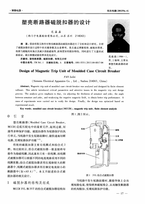
图1 3 V L拍合式磁脱扣器
1 磁脱扣器 的结构及 组成
MC C B 3 V L和 3 V T的拍 合 式磁脱 扣 器结 构如
当线 路 中发 生 短路 故 障 时 , 激励 导体 上 会 出
了磁脱扣器 在设计过 程中 的关 键参 数及 注意 事项 。重 点通 过调 整衔 铁 、 磁 轭 的厚度 , 衔铁与磁轭 的夹 角以及减 少消极磁场等 , 获得更好 的脱 扣特 性。 同时进行 了大量 的试 验验证 。最后根据试验结果来优化设计 。
关 键 词 :塑 壳 断 路 器 ; 磁 脱 扣器 : 有 限元 分 析 中图分类号 : T M 5 6 1 . 1 文 献 标 志码 : A 文章编号 : 1 0 0 1 - 5 5 3 1 ( 2 0 1 3 ) 0 4 - 0 0 1 7 - 0 4 范 磊磊 ( 1 9 8 4 一) , 男, 工程 师 , 主 要 从
p r o c e s s .T h e a n a l y s i s g i v e s e mp h a s i s t o t h a t ,v i a a d j u s t i n g t h e t h i c k n e s s o f a r ma t u r e a n d y o k e ,t h e a n g l e
b e t we e n a r ma t u r e a n d y o k e,a n d we a k e n i n g t h e n e g a t i v e ma g n e t i c f i e l d,t o o b t a i n b e t t e r t r i p p e r f o r ma n c e .A ma s s o f e x p e r i me n t s we r e c a r r i e d o u t t o v e r i f y t h e d e s i g n . F i n a l l y ,t h e d e s i g n wa s o p t i mi z e d b a s e d o n
如何整定断路器1

Schneider Electric - Division - Name – Date
25
Masterpact MT 脱扣单元整定步骤
短延时保护设定
根据断路器额定电流In,长延时整 定电流值Ir,短延时动作电流值If, 短延时动作时间值tf,设定短延时旋 钮Isd, tsd 位置; 设定步骤: 1. 选择Isd值 ● 短延时保护电流的设定公式为Isd=
断路器过载电流的大小而变化 ;当短路电流大于10Ir 后, 定时限和反时限短延时保护的
对应的定时限延时时间为0.2s,而反时限特性的延 时约为0.4s。
延时时间相同。
Schneider Electric - Division - Name – Date
27
Masterpact MT 脱扣单元整定步骤
2
目录
I. 低压断路器整定步骤
Masterpact MT 脱扣单元整定步骤 Compact NSX 脱扣单元整定步骤
II.低压断路器的选择性保护整定
Schneider Electric - Division - Name – Date
3
I. 低压断路器整定步骤
低压输配电系统中,正确整定低压断路器是提高供电可靠性的重要手段 。
1、单台
Izd2 ≥1.2I q•M 短延时脱扣器 2、干线
Izd2 ≥1.2[Ijs(n-a)+a*I q•M] (a为同时启动的台数) 同时启动合并按一台计
1、单台 Izd3 ≥(2.0~2.5)I q•M
瞬时脱扣器 2、干线
Izd3 ≥1.2[Ijs(n-a)+a*I q•M] (a为同时启动的台数) 同时启动合并按一台计
西门子断路器说明书

真空断路器 3AH3 7.2KV-36KV(2)真空灭弧室图2/5给出了用于3AH3真空断路器中的真空灭弧室的基本结构的剖视图。
根据型号,真空灭弧室(30.)被固定在上支架(20.)。
电弧室(33.)安装在两个陶瓷绝缘子(32.)之间。
静触片(31.)被直接连接在柜上。
动触片(36.)被安装固定在导轨(35.)中的接线端子螺栓(36.1)上。
金属波纹管形成到灭弧室的真空密封连接。
图2/5真空灭弧室安装在3AH3真空断路器中的真空灭弧室被定型核准符合联邦德国的X 射线规则。
它们符合1987年1月8号(联邦法公报第144页)§8规定的X 射线规则的要求和附件Ⅲ第5部分规定的额定瞬间交流电压符合DIN VDE/IDE 标准。
补充说明基本型号的真空断路器包括:带有机械和电气反转的电气操作机械(储能电动机)(M1)合闸线圈(Y9)脱扣分路(Y1)64头带金属孔眼套筒的低压插塞式连接器(X0)辅助开关,6常开+6常闭(S1)“合闸线圈储能”信号的位置开关(S41,S42)断路器分闸信号,信号复位开关(S6,S7)操作次数计数器防止误合闸的闭锁每个3AH3真空断路器也可以装有下面一些设备:接线板(X0)扩展的辅助开关,12常开+12常闭(S1)脱扣分路3AX1101 (Y2)电流互感器操作脱扣3AX1102 (Y4,Y5)电流互感器操作脱扣3AX1104(0.1WS)(Y6)低电压脱扣3AX1103 (Y7)手动电气合闸机械闭锁除标准的脱扣分路外,3AH3真空断路器也可以最多安装两个3AX11型脱扣分路。
在一览表HG11中声明了容许的辅助设备组合和特定的型号。
安装在配电柜或手车上安装供应的3AH3真空断路器是敞开的,可以看到“和闸弹簧脱扣”指示。
在安装3AH3真空断路器之前,先移走运输设备(制动器和定位器)。
根据提供的图纸,面向松开的相间隔板安装。
在将3AH3真空断路器安装进柜中或手车上之前,检查它的额定铭牌数据(避免混乱),比较交货单指明的额定电压与本地可供的电源电压。
西门子3WT断路器脱扣器整定说明

电子部件66.1过电流脱扣器 - 功能概述注意我们已经检查了本手册的内容以确保其与描述的硬件和软件一致。
但是也不能完全排除差异情况,因此我们不能担保此处所提供信息的正确性。
会定期检查本手册中的信息,并在以后版本中包括任何必要的修正。
过电流保护设置小心仅在断路器断开时调整参数。
如果在断路器接通的情况下修改参数,则可能会意外使断路器脱扣。
小心当规划项目和考虑选择性时,必须确保断路器上的负载不超过 3WT 产品目录中规定的分断能力。
就某种程度而言,必须设置上游保护设备才能安全地中断这些故障。
通过旋转编码开关调整所有参数。
电子部件6.1 过电流脱扣器 - 功能概述功能概述过电流脱扣器功能ETU35WT ETU37WT ETU45WT ETU47WT LT:过载保护(长延时),L 脱扣✓✓✓✓热记忆可开/关— — ✓✓ST:短延时短路保护(短延时),S 脱扣✓✓✓✓短延时可开/关— — ✓✓短延时短路保护(可切换为 I2t)— — ✓✓INST:瞬时短路保护(瞬时),I 脱扣✓1)✓1)✓✓瞬时可开/关— — ✓✓N:中性线保护(N 中性线),N 脱扣— ✓✓✓中性线保护可开/关— ✓✓✓GF:接地故障保护,G 脱扣— ✓— ✓接地故障特性曲线可切换为 I2t — — — ✓接地故障报警— — — ✓负载监视— — ✓✓超前信号“L 脱扣” — — ✓✓电机保护功能✓✓✓✓字母数字显示✓✓✓✓通过Cubicle BUS 进行通讯— — ΟΟ通过 Modbus RTU 进行通讯— — ΟΟ测量功能— — ΟΟ通过旋转编码开关进行参数化✓✓✓✓附加功能的远程参数化— — ✓✓可连接至外部 24 V 直流电源— — ✓✓✓标准Ο可选— 不可用1)固定设置电子部件6.2 过电流脱扣器 ETU35WT 6.2过电流脱扣器 ETU35WT1)只要过电流脱扣器在脱扣之前已经激活超过 20 分钟,则脱扣原因会保存至少两天。
2.断路器保护电流值的整定
断路器保护电流值的整定1.脱扣器额定电流,断路器框架等级额定电流1).脱扣器额定电流:断路器脱扣器额定电流指断路器主触点的额定电流值。
2).断路器壳架等级额定电流Inm:指基本几何尺寸相同和结构相似的框架或塑料外壳中能装的最大脱扣器的额定电流。
举个例子:DZ20Y-100/3300-80ADZ表示塑壳式断路器,20表示设计序号,Y为一般型(指的是额定极限短路分断能力级别),100A表示断路器框架等级额定电流,80A表示脱扣器额定电流,3300中3表示3极,300表示热磁脱扣器。
同一系列中有多种壳架等级额定电流,例如DZ20系列中有100、225、400、630、800、1250等壳架等级额定电流。
同一壳架等级额定电流中又有多种脱扣器额定电流,例如100A壳架等级额定电流中有16A、20A、25A、32A、40A、50A、63A、80A、100A等脱扣器额定电流;225A壳架等级额定电流中有100A,125A、160A、180A、200A、225A脱扣器额定电流。
DZ20-100和DZ20-225两种壳架等级中都有100A脱扣器额定电流,但断路器体积外形和分断能力不相同。
2.热磁脱扣、电子脱扣1).热磁脱扣是复式脱扣,它包含热脱扣、电磁脱扣两个功能。
热脱扣是通过双金属片过电流延时发热变形推动脱扣传动机构,用于过载保护;电磁脱扣是通过电磁线圈的短路电流瞬时推动衔铁带动脱扣,用于短路保护。
2).电子脱扣可以有以上所有功能,并可以方便地进行整定。
电子脱扣器就是用电子元件构成的电路,检测主电路电流,放大、推动脱扣机构。
优缺点:热磁脱扣性能稳定且不受电压波动影响、寿命长、灵敏度低;(推荐使用)电子脱扣功能完善、灵敏度高、整定方便、受电源影响、略易损坏。
适用场合:要求不高而且参数固定不变的一般采用热磁脱扣器,够经济。
精度要求较高,参数需要设定或改变的一般采用电子脱扣器,够安全。
3.施耐德断路器Ir、Tr、Ii、Isd、Tsd参数含义1).Ir-过载长延时脱扣电流整定值2).Tr-过载长延时脱扣时间整定值3).Ii-短路瞬时脱扣电流整定值4).Isd-短路短延时脱扣电流整定值5).Tsd-短路短延时脱扣时间整定值4.过载长延时,短路短延时,短路瞬时脱扣电流整定值1.断路器的整定电流Ir:脱扣器整定到动作的电流值。
低压塑壳断路器动作电流整定与故障处理
低压塑壳断路器动作电流整定与故障处理摘要:本文主要阐述了低压塑壳断路器动作电流整定,对低压断路器常见故障进行了分析,并提出了这些故障的一般处理措施。
关键字:低压塑料外壳断路器动作电流整定故障处理低压断路器又称自动开关或自动空气断路器,是低压配电系统中重要的控制电器之一,能承载、接通、分断正常工作电流,亦能接通、短时承载及分断短路电流的电器。
按结构可分框架式断路器(万能式断路器)和塑壳式断路器两大类。
塑壳式断路器型号比较多,如CM1型、HM3型、DZ20型、HSM1型、RM1型、S1N型、S2N型、LJM2E 型等,具有结构紧凑、体积小、分断高、飞弧短、可自行设定保护特性,操作简单等优点,目前广泛应用在配电低压系统中,一般安装在配电变压器低压侧配电箱内,保护线路和电源设备不受损坏。
一、低压塑壳断路器动作电流整定塑壳式断路器的保护系统是热动—电磁脱扣器型,过载长延时动作采用热双金属元件脱扣,短路瞬时动作采用电磁铁系统动作。
长延时动作功能是为了满足过负荷保护的需要,而瞬时动作功能则是为了满足短路保护的需要,配电网中的过负荷和短路现象也都有瞬时性或永久性之分,加之配电网结构往往由多级开关设备组成。
因此,只有同时具备两种功能,才有可能使保护装置的动作具有选择性、速动性、灵敏性和可靠性。
(一)配电变压器低压总断路器的动作电流整定。
1、瞬时脱扣器的动作电流应避开网络中出现的尖峰负荷,并能在最小短路电流的情况下正确动作,一般为控制器额定电流的5-10倍。
如断路器额定电流大于250A 时,瞬时动作电流整定值可在5-10倍中选择,一般在订货时提出要求,由制造厂整定出厂。
2、长延时脱扣器的动作电流可根据配电变压器低压侧允许的过负荷电流来确定。
(二)配电变压器低压分路断路器的动作电流整定。
配电变压器低压分路断路器脱扣器的动作电流应比上一级脱扣器的动作电流至少低一个级差。
具体整定方法如下:1、瞬时脱扣器的动作电流应避开回路中出现的尖峰负荷。
Siemens Power Break II 电路断路器电流脱落与电流脱落与锁定辅助设备说明书
IntroductionThe Shunt Trip and Shunt Trip with Lockout accessories, shown in Figure 1, can be installed in 800–4000 ampere frame Power Break® II circuit breakers. These accessories allow the breaker to be tripped electrically from a remote location.In addition to providing a trip signal to the breaker, the Shunt Trip accessories can be set up to interact with other Power Break II accessories, when used with a MicroVersaTrip Plus™or MicroVersaTrip PM™ Trip Unit. DIP switches on the rear of the breaker Trip Unit can configure the Shunt Trip accessories to activate a Bell Alarm–Alarm Only accessory or a Bell Alarm with Lockout accessory when a s hunt trip occurs. The Accessory Configuration section below describes how this can be done. If the breaker is equipped with a Power+™ Trip Unit, it is configured so that only protection trips will activate a Bell Alarm–Alarm Only or Bell Alarm with Lockout.The catalog numbers for the Shunt Trip and Shunt Trip with Lockout for 480 and 600 Vac are listed in Table 1. Voltage and current ratings in Table 1 are given at the input of the transformer. The voltage and current ratings of the input to the accessory are equal to that of the 120 Vac version of the accessory. Table 2 lists these ratings.OperationApply control voltage to the primary of the supplied step-down transformer. The secondary of the transformer is connected t o terminals 31 and 32 of the terminal strip on the right side o f the breaker.WARNING:480 Vac and 600 Vac Shunt Trip accessories must be used with the supplied step-down transformer.AVERTISSEMENT: Les modules de déclenchement shunt 480 Vac et 600 Vac doivent être utilisés avec le transformateur abaisseur de tension qui est fourni.The Shunt Trip or Shunt Trip with Lockout will cause the circuit breaker to trip when the control voltage is greater than 55% of the rated ac value. Control power to the Shunt Tripmust be removed before the breaker can be closed. Control power to the Shunt Trip with Lockout must be removed for a minimum of 0.25 second before the breaker can be closed.Figure 1. Shunt Trip with LockoutCatalogNumberVoltageRating➀Peak InrushCurrent, mA➁Nominal RMSCurrent, mA SPST480480 Vac37521SPST600600 Vac30017SPSTL480480 Vac75020SPSTL600600 Vac60016➀Rated for 50/60 Hz. Rating is 120 Vac without step-down transformer.➁Peak inrush current is present fo r 2–6 ms after activation. This number is provided so that fuses and supplies can be chosenappropriately.Table 1. Catalog numbers and voltages for the Shunt Trip and ShuntTrip with Lockout.AccessoryVoltageRatingPeak InrushCurrent, ANominal RMSCurrent, mA Shunt Trip120 Vac 1.585Shunt Trip/Lockout120 Vac380 Table 2. Voltage and current ratings for the 120 Vac Shunt Trip andShunt Trip with Lockout.InstallationWARNING: Before installing any accessories, turn the breaker OFF, disconnect it from all voltage sources, and discharge the charging springs.AVERTISSEMENT:Avant d’installer tout accessoire, mettre le disjoncteur en position OFF, le déconnecter de toute tension d’alimentation, et décharger les ressorts d’armement.The Shunt Trip or Shunt Trip with Lockout is installed in the accessory compartment through the front of the circuit breaker i n the position shown in Figure 2.gPower Break® II Circuit BreakerAccessoriesShunt Trip and Shunt Trip with Lockout480 & 600 VacFigure 2. Accessory compartment on front of circuit breaker, withShunt Trip slot e the following procedure to install the Shunt Trip accessory into the Shunt Trip slot of the accessory compartment:1.Open the hinged door over the accessory compartment and Trip Unit.2.To remove an existing accessory, loosen the accessory locking screw and pull the accessory out with the Rating Plug Removal Tool (catalog number TRTOOL).3.Insert the Shunt Trip accessory into the proper slot, as illustrated in Figure 3. The Shunt Trip accessory is keyed for the correct slot in the accessory compartment. If t h e accessory cannot be fully seated in the compartment, c h e c kthat the compartment position is correct.Figure 3. Inserting a Shunt Trip into the accessory compartment.4.Tighten the locking screw on the front of the accessory until it is snug (9 in-lb).CAUTION: Overtightening the locking screw may damage o r distort the case of the accessory.ATTENTION: Le serrage excessif de la vis de verrouillage peut déformer le boîtier d’accessoire.5.If the breaker is equipped with a MicroVersaTrip Plus o r MicroVersaTrip PM Trip Unit, the Shunt Trip accessory can be congifured to activate installed Bell Alarm–Alarm Only or Bell Alarm with Lockout accessories when a shunt trip occurs, with the procedure described in the Accessory Configuration section.6.Mount the supplied step-down transformer near the circuit breaker.7.Connect the control wiring for either Shunt Trip to the primary side of the transformer, marked as the H numbered terminals. Table 3 lists the correct transformer primary taps.8.Connect the secondary side of the transformer, marked as the X numbered terminals, to terminals 31 and 32 of the terminal block on the right side of the breaker. Table 3lists the correct transformer secondary taps.WARNING: 480 Vac and 600 Vac Shunt Trip accessories must be used with the supplied step-down transformer.AVERTISSEMENT: Les modules de déclenchement shunt 480Vac et 600 Vac doivent être utilisés avec le transformateur abaisseur de tension qui est fourni.Catalog Number/Control VoltagePrimary Connections Secondary Connections9T58K0042480 V H1, H4➀X1, X29T58K0062600 VH1, H4X1, X3➀ A jumper must be placed from H2 to H3.Table 3. Primary and secondary connections for step-downtransformers.9.Test the Shunt Trip to ensure proper operation, according to the procedures below.10.Reconnect power to the circuit breaker and any otheraccessories.11.Close and lock or seal the door over the accessorycompartment and Trip Unit to prevent unauthorized changes to Trip Unit settings and to keep contaminants out of empty accessory slots.Accessory ConfigurationThis section only applies if Bell Alarm–Alarm Only or Bell Alarm with Lockout accessories are installed in the breaker,along with a MicroVersaTrip Plus or MicroVersaTrip PM Trip Unit. If the breaker is equipped with a Power+ Trip Unit, the factory default settings, listed in Table 4, can not be changed.The Shunt Trip accessory can be configured to activate the Bell Alarm–Alarm Only or Bell Alarm with Lockout accessories if a shunt trip occurs. The configuration can be changed by removing the Trip Unit from the breaker, setting the DIP switches on the rear of the Trip Unit, and reinstalling the Trip Unit. Figure 4 illustrates the Trip Unit rear DIP switches and their functions. Table 4 lists the switch functions and the factory settings for each.Description of Switch SettingsFollowing are descriptions of the effects of each accessory switch when it is enabled .1.When a Shunt Trip accessory causes the breaker to trip,the contacts of the Bell Alarm–Alarm Only also change state. (The factory switch setting is disabled .)Figure 4. Accessory switch on the rear of the MicroVersaTrip Plus™ or MicroVersaTrip PM™ Trip Unit, showing the factory settings (solidpart indicates that the switch is pushed in on that side).Switch Factory Setting Function1Disabled Shunt trip activates Bell Alarm–Alarm Only2Disabled UVR trip activates Bell Alarm–Alarm Only3Enabled Protection trip activates Bell Alarm–Alarm Only4Disabled Shunt trip activates Bell Alarm with Lockout5Disabled UVR trip activates Bell Alarm with Lockout6EnabledProtection trip activates Bell Alarm with LockoutTable 4. Accessory switch settings, including the factory defaults.2.When an Undervoltage Release accessory causes the breaker to trip, the contacts of the Bell Alarm–Alarm Only also change state. (The factory switch setting is disabled .)3.When a protection trip (long-time, short-time,instantaneous, ground-fault, or protective-relay) occurs,the contacts of the Bell Alarm–Alarm Only also change state. (The factory switch setting is enabled .)4.When a Shunt Trip accessory causes the breaker to trip,the contacts of the Bell Alarm with Lockout also change state. (The factory switch setting is disabled .)5.When an Undervoltage Release accessory causes the breaker to trip, the contacts of the Bell Alarm with Lockout also change state. (The factory switch setting is disabled .)6.When a protection trip (long-time, short-time,instantaneous, ground-fault, or protective-relay) occurs,the contacts of the Bell Alarm with Lockout also change state. (The factory switch setting is enabled.)Procedure for Changing Switch SettingsChange the accessory switch settings with the following procedure:WARNING: Before beginning this procedure, turn the breaker off, disconnect it from all voltage sources, and discharge the closing springs.AVERTISSEMENT: Avant de commencer cette procédure,mettre le disjoncteur en position OFF, le déconnecter de toute tension d’alimentation, et désarmer les ressorts de fermeture.1.Loosen the four #8-32 screws on the breaker trim-plate assembly and remove the trim plate.2.Loosen the four #10-32 screws at the corner of the breaker cover. Remove the cover from the breaker face.3.Pull the Trip Unit locking lever to the right, then hold the Trip Unit near the battery cover and lift it straight out o f the breaker.4.Refer to Figure 4 and Table 4 to determine the switches t o be changed.5.Push in the appropriate “Enable” or “Disable” side of the switch.6.Confirm all switch settings before reinstalling the Trip Unit in the breaker.7.Pull the Trip Unit locking lever to the right. While holding the lever, carefully align the connector on the rear of the Trip Unit with the connector in the breaker. Press down on the Trip Unit, while holding it near the battery cover.When the Trip Unit is fully seated, slide the locking lever back to the left.8.Reinstall the breaker top cover and tighten the four #10-32screws to 32 in-lb.9.Replace the trim plate and tighten the four #8-32 screws to 20 in-lb.10.Verify that the switch settings are correct by inducingbreaker trips from the Shunt Trip and Undervoltage Release (if present) and checking the responses of the Bell Alarm–Alarm Only and Bell Alarm with Lockout accessories.Test ProcedureTest the Shunt Trip for proper operation with the following procedure.1.Turn off the power to the Shunt Trip.2.Close the breaker contacts.3.Apply at least 55% of the rated ac voltage to the Shunt Trip; the breaker should trip immediately.4.If a Bell Alarm–Alarm Only or Bell Alarm with Lockout is present, ensure that they activate (or do not activate) as selected by the MicroVersaTrip Plus or MicroVersaTrip PM Trip Unit DIP switches.If a Shunt Trip with Lockout has been installed, continue with the following steps:5.After the breaker has tripped and with the power still applied to the Shunt Trip with Lockout, attempt to close the breaker. The breaker should not close nor attempt t o close.6.If a MicroVersaTrip Plus or MicroVersaTrip PM Trip Unit is installed, check that t h e Trip Unit display is active (powered).7.Remove power from the Shunt Trip with Lockout.8.Attempt to close the breaker; it should close as normal.Trouble-ShootingThe following guide is provided for trouble-shooting and isolating c o m m o n problems. It does not cover every possible situation. Contact the ED&C Customer Support Center at 800-843-3742 if any problem is not resolved by these procedures.Symptom Possible Cause Corrective Action1.The Shunt Trip accessorywill not insert completelyinto the breaker.The accessory is insertedincorrectly.Ensure that the accessory is inserted in the correct slot, asin Figure 2, and that the label is upright.2.The breaker will not tripwhen control power isapplied to the Shunt Trip.The Shunt Trip is not energized.The installed Shunt Trip has anincorrect voltage rating.The transformer connections areincorrect.The Shunt Trip connection ispoor.The breaker is not closed.Check that Shunt Trip control power is applied at greater than 55% of the rated ac voltage. Check that the accessory is completely inserted; reinsert if necessary.Check for the proper voltage rating on the Shunt Trip.Ensure that steps 6, 7, and 8 in the Installation section have been followed correctly.Check that the Shunt Trip accessory is completely inserted. Check that the Trip Unit is seated correctly. If the Trip Unit was removed to set the switches, check that it has been correctly installed; remove and reinstall, if necessary.Note that an otherwise unpowered Trip Unit would be powered up by an energized Shunt Trip accessory. Verify that the breaker is closed.3.The breaker closesmanually when the ShuntTrip with Lockout isenergized.The Shunt Trip with Lockoutsolenoid is not energized.The Shunt Trip with Lockoutcontrol power connection is poor.Check that the Shunt Trip with Lockout control power isapplied at greater than 55% of the rated ac voltage. Checkthat the accessory is completely inserted; re-insert ifnecessary.Note that an otherwise unpowered Trip Unit is poweredby an energized Shunt Trip accessory.Check that the Shunt Trip with Lockout accessory iscompletely inserted.4.The breaker will not closemanually when the ShuntTrip or Shunt Trip withLockout control power isremoved.The Shunt Trip or Shunt Tripwith Lockout control power isactually still applied.The breaker is already closedThe Shunt Trip with Lockoutplunger is not retracted.Check that the Shunt Trip or Shunt Trip with Lockoutcontrol power has been removed.Check that the breaker is not closed; if so, open it and tryagain.Remove the Shunt Trip with Lockout accessory. If thelockout plunger protrudes out of the accessory, replacethe accessory. If the plunger does not protrude, reinsertthe accessory, ensuring good alignment of the accessoryin the pocket.5.The breaker fails to closeafter control power isremoved from the ShuntTrip with Lockout.Control power was not removedfor a minimum of 0.25 secondsbefore the breaker was closed.Wait at least 0.25 seconds before closing the breaker afterremoving control power from the Shunt Trip.These instructions do not cover all details or variations in equipment nor do they provide for every possible contingency that may be met in connection with installation, operation, or maintenance. Should further information be desired or should particular problems arise that are not covered sufficiently for the purchaser’s purposes, the matter should be referred to the GE Company.gGE Electrical Distribution & ControlGeneral Electric Company41 Woodford Ave., Plainville, CT 06062GEH-6519B 0697© 1997 General Electric Company。
西门子3WT断路器脱扣器整定说明
电子部件66.1过电流脱扣器 - 功能概述注意我们已经检查了本手册的内容以确保其与描述的硬件和软件一致。
但是也不能完全排除差异情况,因此我们不能担保此处所提供信息的正确性。
会定期检查本手册中的信息,并在以后版本中包括任何必要的修正。
过电流保护设置小心仅在断路器断开时调整参数。
如果在断路器接通的情况下修改参数,则可能会意外使断路器脱扣。
小心当规划项目和考虑选择性时,必须确保断路器上的负载不超过 3WT 产品目录中规定的分断能力。
就某种程度而言,必须设置上游保护设备才能安全地中断这些故障。
通过旋转编码开关调整所有参数。
电子部件6.1 过电流脱扣器 - 功能概述功能概述过电流脱扣器功能ETU35WT ETU37WT ETU45WT ETU47WT LT:过载保护(长延时),L 脱扣✓✓✓✓热记忆可开/关— — ✓✓ST:短延时短路保护(短延时),S 脱扣✓✓✓✓短延时可开/关— — ✓✓短延时短路保护(可切换为 I2t)— — ✓✓INST:瞬时短路保护(瞬时),I 脱扣✓1)✓1)✓✓瞬时可开/关— — ✓✓N:中性线保护(N 中性线),N 脱扣— ✓✓✓中性线保护可开/关— ✓✓✓GF:接地故障保护,G 脱扣— ✓— ✓接地故障特性曲线可切换为 I2t — — — ✓接地故障报警— — — ✓负载监视— — ✓✓超前信号“L 脱扣” — — ✓✓电机保护功能✓✓✓✓字母数字显示✓✓✓✓通过Cubicle BUS 进行通讯— — ΟΟ通过 Modbus RTU 进行通讯— — ΟΟ测量功能— — ΟΟ通过旋转编码开关进行参数化✓✓✓✓附加功能的远程参数化— — ✓✓可连接至外部 24 V 直流电源— — ✓✓✓标准Ο可选— 不可用1)固定设置电子部件6.2 过电流脱扣器 ETU35WT 6.2过电流脱扣器 ETU35WT1)只要过电流脱扣器在脱扣之前已经激活超过 20 分钟,则脱扣原因会保存至少两天。
- 1、下载文档前请自行甄别文档内容的完整性,平台不提供额外的编辑、内容补充、找答案等附加服务。
- 2、"仅部分预览"的文档,不可在线预览部分如存在完整性等问题,可反馈申请退款(可完整预览的文档不适用该条件!)。
- 3、如文档侵犯您的权益,请联系客服反馈,我们会尽快为您处理(人工客服工作时间:9:00-18:30)。
In 16 A 20 A 25 A 32 A 40 A 50 A 63 A 80 A
100 A 125 A 160 A
Ir 11 … 16 A 14 … 20 A 18 … 25 A 22 … 32 A 28 … 40 A 35 … 50 A 44 … 63 A 56 … 80 A 70 … 100 A 88 … 125 A 112 … 160 A
100 A 16 A 20 A 25 A 32 A 40 A 50 A 63 A 80 A
100 A 125 A 160 A
Ii 320 A 320 A 320 A 320 A 400 A 500 A 630 A 800 A
1.000 A 320 A 320 A 320 A 320 A 400 A 500 A 630 A 800 A
0%, 50%, 100% 0%, 50%, 100% 0%, 50%, 100%
Unrestricted © Siemens AG 2016. All rights reserved.
Page 5
January 2016
EM LP SI TM
3VA1 塑壳断路器 TM240 ATAM (3VA1)
电机保护: • ETU350M LSI 电机起动器: • ETU310M I
• 菜单式显示屏 • 可配置通信附件实现通信功能 • 可配置外部零线测量互感器(N-CT)
线路及发电机保护: • ETU550 LSI • ETU560 LSIG
• 菜单式显示屏 • 可配置通信附件实现通信功能 • 可配置外部零线测量互感器(N-CT) • 集成电能测量功能
Characteristic curve
ATAM
Unrestricted © Siemens AG 2016. All rights reserved.
Page 6
January 2016
EM LP SI TM
3VA1 塑壳断路器 TM240 ATAM (3VA11, 3VA12)
Size 160 A (3VA11)
E 1 / 2 / 3 / 4-pole (4-pole w/o N-protection) F 4-pole, 50% N-protection G 4-pole, 100% N-protection
MH AA
TM120M , 3-pole 3VA11 / 3VA12 SD100 , 3-pole / 4-pole 3VA11 / 3VA12
IEC 947
TM240 ATAM • 过载可调 • 短路可调 N线保护, 适用于4极断路器
Front view
100 A – –
160 A 3/4-pole (3VA11)
• 无保护 • 50% In • 100% In
250 A 3/4-pole (3VA12)
• 无保护 • 50% In • 100% In
3VA1 塑壳断路器 脱扣器一览
SD100
LBS FTFM ATFM ATAM
适用于 线路保护 / 隔离开关 / 马达起动器 • 线路保护应用: TM210, TM220, TM240 • 负荷隔离开关: SD100 • 马达起动器: TM120M • 四极断路器零线保护范围(160 A 壳架): • 0%, 50%, and 100% • 选用于交流及直流配电网络 • 环境温度50゜C及以下无降容
FTFM
Unrestricted © Siemens AG 2016. All rights reserved.
Page 2
January 2016
EM LP SI TM
3VA1 塑壳断路器 TM210 FTFM (3VA10, 3VA11)
Size 3VA10
100 A
3VA11
160 A
In 16 A 20 A 25 A 32 A 40 A 50 A 63 A 80 A
Class M, H, C
Class L
160 A (3VA21)
250 A (3VA22)
400 A (3VA23)
630 A (3VA24)
630A (3VA24)
Ir 25 A 40 A 63 A 100 A 25 A 40 A 63 A 100 A 160 A 160 A 250 A 250 A 400 A 400 A 630 A 400 A 630 A
• 无保护 • 50% In • 100% In
250 A – –
Unrestricted © Siemens AG 2016. All rights reserved.
Page 4
January 2016
EM LP SI TM
3VA1 塑壳断路器 TM220 ATFM (3VA11)
Size 160 A
IN (4P) 0%, 100% 0%, 100% 0%, 100% 0%, 100% 0%, 100% 0%, 100% 0%, 100% 0%, 100%
0%, 50%, 100% 0%, 50%, 100% 0%, 50%, 100% 0%, 50%, 100% 0%, 50%, 100% 0%, 50%, 100%
Unrestricted © Siemens AG 2016. All rights reserved.
Page 9
January 2016
EM LP SI TM
3VA2塑壳断路器 电子式脱扣器
ETU 3-系列
ETU 5-系列
ETU 8-系列
• 旋钮式调节,带电流值指示
线路及发电机保护: • ETU320 LI • ETU330 LIG • ETU350 LSI 线路保护: 专为同熔断器配合而创! • ETU340 (ELISA)
EM LP SI TM
3VA1 塑壳断路器 TM220 ATFM (3VA11)
IEC 947
TM220 ATFM • 过载可调 • 短路不可调 N线保护, 适用于4极断路器
Front view
100 A – –
Characteristic curve
ATFM
160 A 3/4-pole (3VA11)
100 A 16 A 20 A 25 A 32 A 40 A 50 A 63 A 80 A
100 A 125 A 160 A
Unrestricted © Siemens AG 2016. All rights reserved.
Page 3
January 2016
Ir 16 A 20 A 25 A 32 A 40 A 50 A 63 A 80 A
Unrestricted © Siemens AG 2016. All rights reserved.
Page 8
January 2016
EM LP SI TM
3VA2塑壳断路器 产品亮点
线路保护 /发电机保护/ 电动机保护/电机起动器
• 4种分断容量等级,自55KA至150KA
• 上下级断路器额定壳架电流比2.5: 1即可实现完 全选择性
Starter
Ii
Unrestricted © Siemens AG 2016. All rights reserved.
Page 1
January 2016
EM LP SI TM
3VA1 塑壳断路器 TM210 FTFM – (3VA10, 3VA11)
IEC 947
TM210 FTFM • 过载不可调 • 短路不可调
Ii 160 … 320 A 160 … 320 A 160 … 320 A 160 … 320 A 200 … 400 A 250 … 500 A 315 … 630 A 400 … 800 A 500 … 1.000 A 625 … 1.250 A 800 … 1.600 A 800 … 1.600 A 1.000… 2.000 A 1.250… 2.500 A
3VA2塑壳断路器 电子式脱扣器-ETU 3系列
• 提供LI, LSI,LIG 及ELISA四种脱扣器类型,其中LIG,ELISA为西门子独有! • 最多至5个保护整定旋钮,带颜色识别
• 过载保护 • 短路短延时或瞬动保护 • 中性线保护 • 以整定值为指示,易于设定 • 整定值可以透明保护盖铅封 • 四极断路器中性线保护定值可调 • LED状态指示灯 • ACT • AL1 (I > 90 % Ir) • AL2 (I > 105 % Ir)
Unrestricted © Siemens AG 2016. All rights reserved.
Page 7
January 2016
EM LP SI TM
3VA1 塑壳断路器 热磁脱扣器代码及含义
9 10 3VA1 __ __ __ – __ __ __ __ – __ __ __ __
D TM210 (FTFM) 3VA10 / 3VA11 E TM220 (ATFM) 3VA11 F TM240 (ATAM) 3VA11 / 3VA12
N线保护, 适用于4极断路器
100 A 3/4-pole (3VA10 / 3VA11)
无保护
Front view
160 A 1/2-pole (3VA11)
–
160 A
3/4-pole (3VA10/3VA11)
• 无保护 • 50% In • 100% In
Characteristic curve
线路及发电机保护: • ETU850 LSI • ETU860 LSIG
电机保护: •–
电机起动器: •–
电机保护: • ETU860M
电机起动器: •–
Unrestricted © Siemens AG 2016. All rights reserved.