无刷直流伺服电机与交流伺服电机的对比
直流电机VS交流电机VS步进电机VS伺服电机_如何正确选择步进电机和伺服电机

什么是直流电机,什么是交流电机,什么是步进电机,什么是伺服电机? (1)一般直流电机与直流伺服电机的区别 (2)直流伺服电动机工作原理是什么? (2)伺服马达的工作原理 (4)伺服马达和步进马达的区别 (5)如何正确选择伺服电机和步 (5)1,如何正确选择伺服电机和步进电机? (5)2,选择步进电机还是伺服电机系统? (5)3,如何配用步进电机驱动器? (6)4,2相和5相步进电机有何区别,如何选择? (6)5,何时选用直流伺服系统,它和交流伺服有何区别? (6)6,使用电机时要注意的问题? (7)7,步进电机启动运行时,有时动一下就不动了或原地来回动,运行时有时还会失步,是什么问题? (7)8,我想通过通讯方式直接控制伺服电机,可以吗? (7)9,用开关电源给步进和直流电机系统供电好不好? (8)10,我想用±10V或4~20mA的直流电压来控制步进电机,可以吗? (8)11,我有一个的伺服电机带编码器反馈,可否用只带测速机口的伺服驱动器控制? (8)12,伺服电机的码盘部分可以拆开吗? (8)13,步进和伺服电机可以拆开检修或改装吗? (8)14,几台伺服电机可以作同步运行吗? (8)15,伺服控制器能够感知外部负载的变化吗? (8)16,可以将国产的驱动器或电机和国外优质的电机或驱动器配用吗? (8)17,使用大于额定电压值的直流电源电压驱动电机安全吗? (8)18,我如何为我的应用选择适当的供电电源? (9)19,对于伺服驱动器我可以选择那种工作方式? (9)20,驱动器和系统如何接地? (10)21,减速器为什么不能和电机正好相配在标准转矩点? (10)22,我如何选择使用行星减速器还是正齿轮减速器? (10)23,何为负载率(duty cycle)? (11)24,标准旋转电机的驱动电路可以用于直线电机吗? (11)25,直线电机是否可以垂直安装,做上下运动? (12)26,在同一个平台上可以安装多个动子吗? (12)27,是否可以将多个无刷电机的动子线圈安装于同一个磁轨道上? (12)28,AMS的直线电机是否可以用于特殊环境,如水溅、真空、洁净室、辐射等环境? (12)29,使用直线电机比滚珠丝杆的线性电机有何优点? (12)30,你们的滑台可以做多个组合一起使用吗? (12)什么是直流电机,什么是交流电机,什么是步进电机,什么是伺服电机?1、什么是直流电机?答:输出或输入为直流电能的旋转电机,称为直流电机2、什么是交流电机答:输出或输入为交流电能的旋转电机,称为交流电机。
直流与交流伺服区别和性能

直流复励电动机:电动机的磁通由两个绕组内的励磁电流产生。 4、直流电动机的技术数据 重点掌握额定效率与额定温升。
额定效率=输出功率/输入功率 额定温升指电动机的温度允许超过环境温度的最高允许值。铭牌上的温升是指电动机绕组的最高温升。
1. 三相异步电动机的基本结构 三相异步电动机的构造也分为两部分:定子与转子。 (1)定子: 定子是电动机固定部分,作用是用来产生旋转磁场。
它主要由定子铁心、定子绕组和机座组成。 (2)转子: 转子是重点掌握的部分,转子有两种,鼠笼式与绕线式。掌握他们各自的特点与区别。
鼠笼式用于中小功率(100k以下)的电动机,他的结构简单,工作可靠,使用维护方便。
绕线式可以改善启动性能和调节转速,定子与转子之间的 气隙大小,会影响电动机的性能,一般气隙厚度为0.2-1.5mm之间。 掌握定子绕组的接线方法。
2. 三相异步电动机的工作原理 掌握公式n1=60f/P、S=(n1-n)/n1、n=(1-S)60f/P,同时明白它们的意义(很重要),要能够灵活运用这些公式,进行计算。
5. 三相异步电动机的起动 (1)直接起动 启动时转差率为1,转子中感应电动势很大,转子电流也很大。
当电动机在额定电压下启动时,称为直接启动,直接启动的电流约为额定电流的5-7倍。
一般来说,额定功率为7.5kw以下的小容量异步电动机可直接起动。 直接起动控制线路所用电器包括组合开关、按钮、交流接触器中间继电器、热继电器及熔断器。
而定子和转子是采用同一电源的,所以,定子和转子中电流的方向变化总是同步的,即线圈中的电流方向变了,同时电磁铁中的电流方向也变,
常用电动机类型及特点

电动机类型及特点一、同步电机与异步电机区别:(均属交流电机)结构:同步电机和异步电机的定子绕组是相同的,主要区别在于转子的结构.同步电机的转子上有直流励磁绕组,所以需要外加励磁电源,通过滑环引入电流;而异步电机的转子是短路的绕组,靠电磁感应产生电流(又称感应电机)。
相比之下,同步电机较复杂,造价高。
应用:同步电机大多用在大型发电机的场合。
而异步电机则几乎全用在电动机场合。
同步电机效率较异步电机稍高,在2000KW以上的电动机选型时,一般要考虑是否选用同步电机。
二、单相异步电动机与三相异步电动机:单项电动机:当单相正弦电流通过定子绕组时,电机就会产生一个交变磁场,这个磁场的强弱和方向随时间作正弦规律变化,但在空间方位上是固定的,所以又称这个磁场是交变脉动磁场。
这个交变脉动磁场可分解为两个以相同转速、旋转方向互为相反的旋转磁场,当转子静止时,这两个旋转磁场在转子中产生两个大小相等、方向相反的转矩,使得合成转矩为零,所以电机无法旋转。
当我们用外力使电动机向某一方向旋转时(如顺时针方向旋转),这时转子与顺时针旋转方向的旋转磁场间的切割磁力线运动变小;转子与逆时针旋转方向的旋转磁场间的切割磁力线运动变大。
这样平衡就打破了,转子所产生的总的电磁转矩将不再是零,转子将顺着推动方向旋转起来。
通常根据电动机的起动和运行方式的特点,将单相异步电动机分为单相电阻起动异步电动机、单相电容起动异步电动机、单相电容运转异步电动机、单相电容起动和运转异步电动机、单相罩极式异步电动机五种。
区别:三相异步电动机采用380V三相供电,单相电机是用220V的电源,而且都是小功率的,最大只有2。
2KW 。
相比于同转速同功率的三相电机,单项电机的效率低、功率因数低、运行平稳性差、且体积大,成本高,但由于单相电源方便,且调速方便,因此广泛用于电动工具、医疗器械、家用电器等。
三、无刷直流电机1、无刷直流电机:无刷直流电机是永磁式同步电机的一种,而并不是真正的直流电机。
直流无刷电机 交流电机 效率

直流无刷电机和交流电机是现代工业中常见的两种电动机类型,它们在不同的工业应用领域具有各自的优势和特点。
本文将从效率的角度出发,对直流无刷电机和交流电机的效率进行比较分析,以帮助读者更好地了解这两种电动机的性能特点。
一、直流无刷电机的效率直流无刷电机是一种采用电子换向技术的电机,与传统的直流电机相比,它具有更高的效率和更低的维护成本。
其主要特点包括:1. 电子换向技术直流无刷电机采用电子换向技术,通过控制电流的方向和大小来实现转子的正常运转,避免了传统直流电机需使用机械换向器的缺点,大大提高了电机的效率和可靠性。
2. 低摩擦损失直流无刷电机采用无刷结构,减少了摩擦损失和换向器的磨损,提高了电机的传动效率,降低了能耗和维护成本。
3. 高控制精度直流无刷电机的控制系统更加精确,可实现精密的速度和转矩控制,适用于需要高精度运动的工业应用。
二、交流电机的效率交流电机是一种常用的电动机类型,它具有结构简单、运行稳定的优点,但在效率方面相对于直流无刷电机存在一定差距,其主要特点包括:1. 结构简单交流电机结构简单,易于制造和维护,成本较低,广泛应用于各种家电和工业设备中。
2. 频率和转速匹配交流电机工作时需要外部的电源频率和转速匹配,若未能达到匹配要求,可能导致效率下降,能耗增加。
3. 起动和制动能耗较大交流电机在启动和制动过程中需要消耗较大的能量,效率相对较低。
三、直流无刷电机与交流电机的效率比较从上述对直流无刷电机和交流电机的效率特点进行分析可知,直流无刷电机在效率方面相对于交流电机具有一定的优势,主要体现在以下几个方面:1. 摩擦损失较小直流无刷电机采用无刷结构,减少了摩擦损失,提高了传动效率,降低了能耗。
2. 控制精度较高直流无刷电机的控制系统更加精确,可实现精密的速度和转矩控制,适用于需要高精度运动的工业应用。
3. 可靠性较高直流无刷电机采用电子换向技术,减少了传统直流电机需使用机械换向器的缺点,大大提高了电机的可靠性和使用寿命。
伺服电机驱动方式比较与选择

伺服电机驱动方式比较与选择引言伺服电机在现代自动化控制系统中广泛应用,其中电机驱动方式的选择对系统性能和效率至关重要。
本文将比较和介绍几种常见的伺服电机驱动方式,并分析其特点和适用场景,帮助读者在实际应用中做出明智的选择。
一、步进电机驱动方式步进电机驱动方式是一种常见且经济实用的选择。
步进电机以脉冲信号驱动,将连续运动转化为离散步进运动。
以下是步进电机驱动方式的优缺点及其适用场景。
优点:1. 简单稳定:步进电机驱动方式结构简单,使用方便,具有较高的可靠性和稳定性。
它不需要反馈传感器,减少了系统的复杂性和成本。
2. 适用范围广:步进电机驱动方式适用于低速高扭矩的应用,如纺织机械、印刷机械等。
它的转矩-速度特性良好,可以实现精确的位置控制。
3. 价格经济:步进电机驱动方式相对其他驱动方式成本较低,更适用于预算有限的应用。
缺点:1. 运行效率低:步进电机驱动方式的效率相对较低,因为它在不实际运转时仍然消耗电能。
2. 振动和噪音:由于步进电机的离散步进运动特性,会引起振动和噪音,对一些对噪音敏感的应用不太适用。
二、直流无刷电机驱动方式直流无刷电机驱动方式是一种高效且灵活的选择,它结合了直流电机的优点和伺服系统的性能。
以下是直流无刷电机驱动方式的优缺点及其适用场景。
优点:1. 高效能:直流无刷电机驱动方式具有高效能,因为它没有机械摩擦,消耗电能较少。
它的高效能可以降低系统能源消耗,提高系统性能。
2. 高速运动:直流无刷电机驱动方式适用于高速运动的应用,如风扇、泵等。
它的转速范围广,转速可通过调节电流进行控制。
3. 可编程控制:直流无刷电机驱动方式具有灵活的控制,可以通过编程方式实现多种运动控制模式,适应不同应用场景的需求。
缺点:1. 系统复杂性:直流无刷电机驱动方式需要使用编码器等传感器进行位置反馈,以实现高精度的位置控制。
这增加了系统复杂性和成本。
2. 成本较高:相对步进电机驱动方式,直流无刷电机的成本较高,不太适合预算有限的应用。
直流无刷电机与交流无刷电机比较

直流无刷电机与交流无刷电机比较
直流无刷电机和交流无刷电机各有其优势和劣势。
直流无刷电机的优势主要包括:
1.效率高,这是因为直流电机的磁场利用率更高;
2.调速性能好,通过电子控制器可以实现无级调速,调速精度高,稳定性好;
3.加速性能好,因为直流无刷电机具有较低的转动惯量,可以在短时间内达到较高的转速;
4.对环境友好,不产生电磁干扰,不会对周围电子设备产生干扰;
5.体积小、重量轻、出力大;
6.耐颠簸震动,噪音低,震动小,运转平滑,寿命长。
直流无刷电机的劣势主要包括:
1.成本相对较高,特别是使用了稀土永磁体的情况下;
2.有限的恒功率范围,大的恒功率范围对获得高的车辆效率是至关重要的,但永磁无刷直流电动机不可能获得大于基速两倍的最高转速;
3.在电机制造过程中,由于大型稀土永磁体可以吸引飞散的金属物体,可能会有一定的危险性。
交流无刷电机的优势主要包括:
1.结构简单、维护简单、成本低;
2.可以适用于各种恶劣环境和气候条件;
3.交流电机启动电流较小,启动转矩大,过载能力强;
4.噪音低,震动小。
交流无刷电机的劣势主要包括:
1.调速性能相对较差,需要使用变频器等设备进行调速;
2.控制精度较低,响应速度较慢;
3.需要定期维护和更换电刷和机械部件。
总体来说,直流无刷电机在调速性能、加速性能和对环境友好等方面具有优势,但成本相对较高。
而交流无刷电机在成本、适用性和维护方面具有优势,但在调速性能和精度控制方面稍逊一筹。
在实际应用中,需要根据具体的应用场景和需求来选择适合的电机类型。
直流电机和交流电机的区别与优缺点详解
直流电机和交流电机的区别与优缺点详解直流电机和交流电机是最常用的电动机类型,它们在结构、工作原理和应用方面有许多区别。
下面将详细解释这两种电机的区别和各自的优缺点。
直流电机是利用电流通过在磁场中旋转的导线来产生力矩的电动机。
它们通常由永磁体提供磁场,通过通电的线圈在磁场中旋转。
直流电机可以通过改变电流的方向来改变转子的旋转方向。
这种电机通常带有刷子与旋转部分(转子)之间的接触,以传递电流。
直流电机的优点包括:启动和停止时扭矩大,转速范围宽,控制性好。
然而,直流电机的缺点是容易磨损刷子,需要周期性维护。
另外,由于刷子的存在,直流电机噪音较大。
交流电机是利用交流电动力学原理工作的电动机。
它们有多种类型,包括异步电机、同步电机和感应电机等。
交流电机的转子由固定磁极和旋转磁极组成,不需要通过刷子来传递电流。
交流电机的优点是结构简单,可靠性高。
与直流电机相比,交流电机无刷子磨损问题,因此也无需常规维护。
此外,交流电机运行平稳,产生较低的噪音。
然而,交流电机转速范围更窄,控制性较差。
总的来说,直流电机和交流电机在设计和应用上有许多区别。
直流电机适用于需要广泛速度调节和大扭矩的应用,如电动车辆、机床和风力发电。
交流电机则适用于许多家用电器、风扇和空调等应用,以及许多工业应用中的恒速工作。
需要注意的是,随着技术的发展和创新,传统的直流电机和交流电机之间的差异正在逐渐减小。
现代无刷直流电机(BLDC)结合了直流电机和交流电机的优点,具有高效率、低噪音和可调速等特点。
此外,变频器技术使得交流电机的转速范围和控制性能得到提高。
综上所述,直流电机和交流电机在结构和工作原理上有区别,各有优缺点。
选择哪种电机取决于具体应用需求,包括所需的转速范围、控制性能和维护要求。
随着技术的进步,直流电机和交流电机之间的差异逐渐减小,新的电机类型也在不断涌现。
交流伺服电机和无刷直流伺服电机在功能上有什么区别
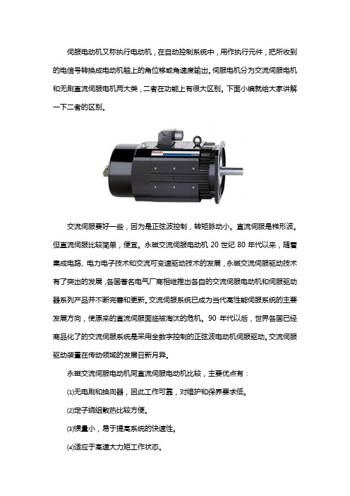
伺服电动机又称执行电动机,在自动控制系统中,用作执行元件,把所收到的电信号转换成电动机轴上的角位移或角速度输出。
伺服电机分为交流伺服电机和无刷直流伺服电机两大类,二者在功能上有很大区别。
下面小编就给大家讲解一下二者的区别。
交流伺服要好一些,因为是正弦波控制,转矩脉动小。
直流伺服是梯形波。
但直流伺服比较简单,便宜。
永磁交流伺服电动机20世纪80年代以来,随着集成电路、电力电子技术和交流可变速驱动技术的发展,永磁交流伺服驱动技术有了突出的发展,各国著名电气厂商相继推出各自的交流伺服电动机和伺服驱动器系列产品并不断完善和更新。
交流伺服系统已成为当代高性能伺服系统的主要发展方向,使原来的直流伺服面临被淘汰的危机。
90年代以后,世界各国已经商品化了的交流伺服系统是采用全数字控制的正弦波电动机伺服驱动。
交流伺服驱动装置在传动领域的发展日新月异。
永磁交流伺服电动机同直流伺服电动机比较,主要优点有:⑴无电刷和换向器,因此工作可靠,对维护和保养要求低。
⑵定子绕组散热比较方便。
⑶惯量小,易于提高系统的快速性。
⑷适应于高速大力矩工作状态。
⑸同功率下有较小的体积和重量。
以上就是由四川志方科技有限公司为大家提供的关于伺服电机的相关信息,为了保证伺服电机使用的稳定性,所有伺服电机都应该在使用前进行测试。
因此,在需要用到伺服电机的企业有必要购进一台专业的伺服电机测试系统。
采购伺服电机测试系统建议咨询专业厂家。
四川志方科技有限公司是一家致力于非标自动化测试系统研发、生产、销售、售后服务为一体的高科技企业,与国内知名高校及研究院所紧密合作,共同开发各种非标自动化测试系统,拥有一支经验丰富的专业团队,其中包括多名长期从事非标测试系统领域的专业人才,产品适用于航天、航空、军工、机械制造、科研、教学等多个领域。
- 1、下载文档前请自行甄别文档内容的完整性,平台不提供额外的编辑、内容补充、找答案等附加服务。
- 2、"仅部分预览"的文档,不可在线预览部分如存在完整性等问题,可反馈申请退款(可完整预览的文档不适用该条件!)。
- 3、如文档侵犯您的权益,请联系客服反馈,我们会尽快为您处理(人工客服工作时间:9:00-18:30)。
AC vs DC Brushless Servo MotorBy John Mazurkiewicz,Baldor ElectricBrushless motors are similar to AC motors since a moving magnet field causes rotor movement. Brushless motors are also similar to PM DC motors since they have predicable linear characteristics.Is this why the brushless is sometimes called AC brushless and sometimes called DC brushless? It is the method of driving or powering the motor from which the name AC or DC is derived. The method of driving the motor will result in different effects (i.e. different torque delivered even from the same motor!).Torque developedTorque developed by a brushless motor depends on the control technology used. A simplified way to determine the type of control is to look at the feedback scheme. DC uses Hall sensors for feedback, whereas AC uses resolver or encoder for feedback. Each of these control methods has its strong points and advantages, which have to be reviewed to determine which is best for an application.By applying a constant current to one winding of a three phase motor, a torque is generated. Since the winding distribution is sinusoidal, torque is not distributed evenly as the shaft is rotated through 360 degrees. As shown in Figure 1, the resulting torque generated is a function of the shaft angular position. Thus, current into a single winding generates a torque that is described by:(1)T+TȀx sin (electrical angle)+TȀx sin fwhere:T = instantaneous torqueT′ = peak value of torqueφ is the electrical angle of the shaftThe electrical angle is different from the mechanical angle, and these are related by:x mechanical angle(2)electrical angle+N2where N is the number of poles.Figure 1 – Sinusoidal emf motorAngle φEquation (1) showed the torque generated by only one winding. In a three phase system, the windings are shifted by 120 electrical degrees, and the equations describing torque per winding are:+TȀpeak x sin f(3)TR+TȀpeak x sin f)120°(4)TS+TȀpeak x sin f)240°(5)TTEnergizing winding R while the rotor is at a position of 30 electrical degrees (see Figure 2) will result in a torque being developed, forcing the shaft to rotate. The shaft will rotate to the 180 electrical degree position and stop. However, if when the shaft is at the 150 electrical degree position, the current is removed from winding R and applied to winding T, the shaft will continue to rotate. If this process is repeated (i.e., current is removed from winding T at 270 degrees and applied to winding S), the shaft will continue to rotate. By continuation of this scheme, rotation is continued.Figure 2 – Energizing sinusoidal emf motorWinding R On"Winding R Off"This illustrates one method of controlling (commutating) the brushless motor, and, of course, other methods exist. But the control scheme, or method of commutating the sinusoidal back emf brushless motor, will affect the back emf and torque constant values, i.e., the values measured versus apparent application results may appear different. The following will cover the sine emf motor, when driven by various methods, and the results attained.DC control/phase–neutral connected motorA sinusoidal emf winding configuration with the neutral grounded, as shown in Figure 3, and a DC current applied to the individual coils conducting for 120 degrees would yield an effective or average back emf of:(6)KE +ŕ5p6p6ǒKȀE f sin f5p*pǓwhere K′Eφ is measured phase to neutral (φ–N) and represents the peak value of the sinusoidal and therefore K E is the average over the waveform.(7)KE+*3KȀE fǒcos 5p*cos pǓ(8)KE +*32pKȀE f(1.73)(9)KE+ 2.59p KȀE f(10)KE+0.826KȀE fFigure 3 – Applying a DC current to a sinusoidal emf motorφK ′E φThe relationship between voltage constant and torque constant are related through:(11)Metric K T f +K E f (N –m/Amps, v/r/s)v/r/s = volts/radians/second(12)English K T f +1.35K E f (oz –in/Amp, V/kRPM)V/kRPM = volts/1000 revolutions/minuteThus the expression for torque becomes:(13)T +K T I(14)Metric T +0.826K ȀE f I (torque in N –m, K E f in v/r/s)or(15)English T + 1.35K E f I (16)T + 1.35x 0.826K ȀE f I(17)T + 1.11K ȀE f I (torque in oz –in,K E in V/kRPM)Keep in mind that K E is easy to measure and verify, whereas the torque constant is more difficult tomeasure. The back emf or voltage constant is measured on a phase to neutral basis, and current is the DC level when the winding is “On ”.With the commutation scheme as explained above, the torque will fluctuate between a high point and a low point, thus giving rise to torque ripple. Figure 4 reveals that the minimum amount of torque will be:(18)T min +T Ȁx sin (30) = 0.5T ’The maximum torque is:(19)T max +T Ȁx sin (90) = T ȀThe torque ripple percent is:(20)%+Max*Min Max+ 1 – 0.51+50%Note that the control should be designed to reduce this torque ripple to an acceptable level for the givenapplication.Figure 4 – Torque ripple from the motor shown in Figure 2φDC control/phase–phase connected motorIn the above discussion, only current in one winding was allowed. If positive and negative currents are applied (that is, applying power across two motor windings), a different picture emerges. As can be seen in Figure 5, with winding R energized (in the 30 electrical degree position), a positive torque is developed. If at the same time a negative current of equal magnitude is applied to winding T, then a positive torque is also developed. The sum of these two torques will be:)(*T T)(21)T+TR(22)T+TȀ sin f*TȀ sin (f+ 240°)(23)T+TȀ x 0.5 – T’ (–1.0)(24)T+TȀ x 1.5Figure 5 – Energizing a sinusoidal emf motor to produce torqueAngle φThis shows that the torque developed by energizing two windings simultaneously is 50% greater than energizing only one winding. This torque results in shaft rotation, and when the shaft reaches the 90 electrical degrees position, current is removed from winding T and applied to winding S (negative current). Again positive torque is developed and rotation continues. An illustration of timing involved when switching (or commutation) from winding to winding is shown in the timing diagram of Figure 6. Since there are six different commutation sections for 360 degrees of rotation, this commutation scheme is referred to assix–step, or DC brushless, control.Figure 6 – Applying a DC current to two windings of a sinusoidal emf motorSSolid lines indicate when the windings are energized.This commutation scheme, i.e., a sinusoidal emf with floating neutral, and the DC control as shown in Figure 7 could have the winding conducting for 60 degrees. This yields an average back emf of:(25)K E +ŕ2p 3p 3ǒK ȀE ff sin f2p 3*p3Ǔwhere K ′E is measured phase to phase (φ–φ) and represents the peak value of the sinusoidal, and K E is therefore the average over the waveform.(26)K E +*3p K ȀE ff ǒcos 2p 3*cos p 3Ǔ(27)K E +*3p K ȀE ff(28)K E +0.955K ȀE ffFigure 7 – Applying a DC current to two windingsφE = 0.955 K ′EEquations (11) and (12) state the relationship between voltage constant and torque constant. Thus, the expression for torque, with a floating neutral, becomes:(29)T+KTI(30)Metric T+0.955KȀE ff I(torque in N–m, KEin vńrńs)or(31)English T+ 1.35KE ffI(32)T+ 1.35x0.955KȀE ffI(33)T+ 1.289KȀE ff I(torque in oz–in, KEin VńkRPM)The back emf or voltage constant is measured on a phase to phase basis, and current is the DC level through the winding, i.e., the DC level when the winding is “On.” Note that Equations (13) through (17) cannot be directly compared to Equations (29) through (33) due to the different “average” values of energized windings, i.e., measuring and energizing phase neutral vs. phase phase.With the commutation scheme above, the maximum torque developed occurs at 60 degrees and is:(34)T max+TȀ(sin(60) – sin (300))(35)T max+TȀx1.73The maximum torque is:(36)Tmin+TȀx1.5The torque ripple percent is:(37)%+Max*MinMax + 1.73*1.51.73+13.2%This represents lower ripple than the situation presented by Equation (20), but comes with the addition of bidirectional current flow. Torque ripple depends on the control scheme. Again the control must be designed to reduce ripple to acceptable application tolerances.AC control/sine motorSuppose that the application of a current whose amplitude is a function of angular position, Equation (38), is applied simultaneously to all three windings (see Figure 8). Since there are feedback devices to generated sinusoidal position information, this approach is possible. When using this approach, the control is often referred to as a sine controller. When energizing all three windings, the output torque developed by the brushless motor is then equal to the sum of the torques in all three phases:(38)I+IȀx(sin f)f phase)(39)TM +T R)TS)T TThe individual phase torques are:(40)TR+K T(R)IȀ(sin f)(41)TS+K T(S)IȀ(sin f))120°(42)TT+K T(T)IȀ(sin f))240°Figure 8 – Driving the sinusoidal emf motor with sinusoidal currentsimultaneously through three windings.K ′EK E φφ RMS = 0.707 K ′E φφI ′Angle φAngle φNote that since the windings are also sinusoidal, previously explained, the individual torque constants are:(43)K T (R)+K ȀT f (sin f )(41)K T (S)+K ȀT f (sin f ))120°(42)K T (T)+K ȀT f (sin f ))240°where peak values for windings R, S, and T are equal and K ′TO is the phase to neutral value. Thus,combining Equations (40), (41), and (42) with Equations (43), (44), and (45) results in:(46)ĂĂT R Ă+ĂK ȀT f ĂsinĂ(f )ĂxĂI Ȁsin f(47)ĂĂT S Ă+ĂK ȀT f ĂsinĂ(f )120°)ĂxĂI ȀsinĂ(f )120°)(48)ĂĂT T Ă+ĂK ȀT f ĂsinĂ(f )240°)ĂxĂI ȀsinĂ(f )240°)Using these equations with substitutions into Equation (39), we arrive at:(49)ĂĂT M Ă+ĂK ȀT f ĂI Ȁ[sin 2f )sin 2(f )120°))sin 2(f )240°)]An important note to remember here is K ′T φ is the peak value of the phase to neutral torque constant and I ′is the peak value of the sinusoidal current (not the RMS). Equation (49) can be reduced to:(50)ĂĂT M Ă+ĂK ȀT f ĂI ȀĂxĂ1.5With this commutation scheme, there is no difference between the maximum and minimum torque developed. Therefore, there is no torque ripple (ideal) when employing a sine controller with a sine emf motor. Equation (50) provides an expression for torque developed in terms of torque constant as measured from phase to neutral. However, with most motors the neutral is not accessible. Therefore, an equivalent phase to phase expression is desired. The equation is developed as follows:(51)ĂĂK T fĂxĂ2Ă+ĂK T ff(52)ĂĂIȀĂ+ĂI RMS .707(53)ĂĂKȀTĂ+ĂK TĂRMS .707These can be substituted into Equation (50), with the result:(54)ĂĂTĂ+Ăǒ1.5ĂKȀT ff2ǓĂxĂǒI RMS.707ĂǓĂ+Ă1.0608KȀT ffĂI RMS(55)ĂĂTĂ+Ăǒ1.0608ĂK T ffĂRMS.707ǓĂxĂǒI RMSǓ(56)ĂĂTĂ+Ăǒ1.5ĂK T ffĂRMSǓĂxĂǒI RMSǓThis equation provides a relationship between torque developed, the RMS current (which can be measured), and the phase to phase torque constant of the motor. However, K T cannot be easily measured. The saving factor is the K E on a phase to phase basis is very easy to measure. Simply by observing the motor’s back emf waveform on a scope (when driving the motor by some external means) and measuring that waveform, the value for K E can be determined. K E is simply volts divided by kRPM. Then, by using the appropriate conversion factor to convert from K E to K T, Equation (56) may be used.K E and K T RelationshipThe relationship between the torque constant and voltage constant can most easily be derived by analyzing the system using the metric approach. The phase to neutral analysis provides:(57)KT f+K E fwhere K T is in N–m/amp and K E is v/r/s.Since in a three phase Wye connected system:(58)2x KT f+K T ff(59)3Ǹx K E f+K E ffTherefore:(60)KT ff +23ǸK E ff(61)KT ff+1.15473K E ff(N*mńamp)(vńrńs)This is the basic equation (in metric) for the relationship of torque constant versus voltage constant for a three phase motor when driven with a three phase excitation. From this the other dimension systems can be derived:(62)KT ff+11.039x10*3K E ff(N*mńamp)(vńrńs)(63)KT ff+97.698x10*3K E ff(lb*inńamp)(VńKRPM)(64)KT ff+1.563K E ff(oz*inńamp)(VńKRPM)Substituting Equation (60) into Equation (56) provides:(65)T+ 1.523ǸKE ff RMSIRMS(66)T+3ǸK E ff RMS I RMS(with K E in vńrńs) or:(67)T+KT ff RMS I RMSwith:(68)KT ff RMS +3ǸKE ff RMS(N–m/amp)(vńrńs)This provides the relationship between torque developed, the RMS current, and the measurable voltage constant of the motor. Note that current and voltage constant are expressed in RMS terms, i.e., RMS of a sinusoidal waveform. By simply measuring the motor’s peak value of K E, using a scope, the developed torque may now be easily calculated.Table 1 summarizes the relationship of a sinusoidal emf motor when driven with either a DC drive or an AC drive. By multiplying the peak value of the sine back emf times the factor in the table, the equivalent, or RMS, value is determined. This RMS value can then be used in calculations, and the sine emf motor is treated as an ordinary PMDC motor.Table 1Table 2 shows and example calculation for the RMS values for a motor driven as a generator at 1,000 RPM with back emf (peak value) measured as 75 V/kRPM peak phase to phase.If the example load were 400 oz–in (2.82 N–m) and the motor were powered by a six–step control (vs. a sine control) the currents would be 4.1 Amps instead of 3.2 Amps respectively.Table 2。