优科无线控制器配置手册
优科无线AP 设置
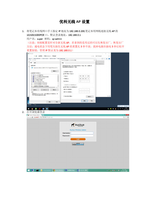
优科无线AP设置1.将笔记本有线网口手工指定IP地址为192.168.0.200,笔记本用网线连接无线AP的10/100/1000POE口,默认登录地址:192.168.0.1用户名:super 密码:sp-admin(注意:初始配置是针对全新无线AP,若拿到的是用过的可以先恢复出厂,恢复出厂方法:通电状态下用笔尖按住无线AP的重置孔5秒不放,拔掉电源在插电5秒后松开重置按钮,管理IP默认变为192.168.0.1)2.打开浏览器登录3.更改默认登录密码:4.指定DNS,此步骤可以默认即可6.开启DHCP功能5.修改列表中2.4G信息注意:若教室周围有较强的2.4G信号,可以在平板上安装“wifi概观360”软件扫描下周围的无线信号所占用的Channel,然后将我们的设备和周围的Channel错开,2.4G信号Channel选择1、6、11相互间干扰最小。
8.添加2.4G学生信号ChangyanSTU,设置ssid及密码9.修改5G 显示信息Channel可以修改为149-169之间的可选频段(注意:畅言智慧课堂对5G无线信号名称要求为ChangyanTCH开头,密码iFlytek1234)下图的标签位置可以查看5G状态,若为UP状态平板搜不到5G信号(不是所有平板和手机都支持5G操作前可以网上查看配置是否支持5G)可以更改Channel153、157、161测试,也可以把上图的Wireless Availability 先Disabled ,保存后,再点击一次Enabled,保存退出,看是否能搜到信号。
10此处按下图配置port1为外网口,port2设置为云服务器连接口。
(注意:靠近电源口的网口为PORT1,若按下图配置后,切勿将外网线插入PORT2,以免造成学校网络中断)常见故障和其它配置其它设置:1.后期可通过无线登录管理界面打开浏览器输入https://192.168.40.1,出现登录画面输入用户名super,密码sp-admin2.指定外网口IP地址上网按下图设置,进入AP管理界面,选择左侧configuration->Internet,输入的IP地址和DNS为现场网管提供。
Ruckus ZoneDirector Smart OS说明书
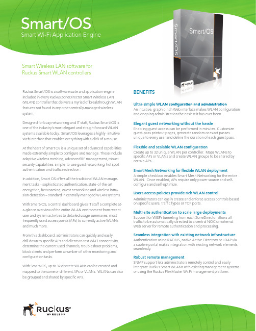
Ruckus Smart/OS is a software suite and application engine included in every Ruckus ZoneDirector Smart Wireless LAN (WLAN) controller that delivers a myriad of breakthrough WLAN features not found in any other centrally-managed wireless system.Designed for busy networking and IT staff, Ruckus Smart/OS is one of the industry’s most elegant and straightforward WLAN systems available today. Smart/OS leverages a highly- intuitive Web interface that enables everything with a click of a mouse. At the heart of Smart OS is a unique set of advanced capabilities made extremely simple to confi gure and manage. These include adaptive wireless meshing, advanced RF management, robust security capabilities, simple-to-use guest networking, hot spot authentication and traffi c redirection .In addition, Smart OS offers all the traditional WLAN manage-ment tasks – sophisticated authentication, state-of-the-art encryption, fast roaming, guest networking and wireless intru-sion detection – standard in centrally-managed WLAN systems.With Smart/OS, a central dashboard gives IT staff a complete at-a-glance overview of the entire WLAN environment from recent user and system activities to detailed usage summaries, most frequently used access points (APs) to currently active WLANs Smart Wi-Fi Application EngineBENEFITSUltra-simple WLAN confiAn intuitive, graphic-rich Web interface makes WLAN configurationand ongoing administration the easiest it has ever been.Elegant guest networking without the hassleEnabling guest access can be performed in minutes. Customize guest-pass printout pages, generate random or exact passes unique to every user and defi ne the duration of each guest pass.Flexible and scalable WLAN confi gurationCreate up to 32 unique WLAN per controller. Maps WLANs to specifi c APs or VLANs and create WLAN groups to be shared by certain APs .Smart Mesh Networking for fl exible WLAN deploymentA simple checkbox enables Smart Mesh Networking for the entire WLAN. Once enabled, APs require only power source and self-confi gure and self-optimize.Users access policies provide rich WLAN controlAdministrators can easily create and enforce access controls based on specifi c users, traffi c types or TCP ports.Multi-site authentication to scale large deploymentsSupport for WISPr tunneling from each ZoneDirector allows all Smart/OSSmart Wireless LAN software for Ruckus Smart WLAN controllersWLAN confi guration and administrationUltra simple confi guration and managementOne of the easiest to manage WLAN systems on the market,Smart/OS enables administrators to confi gure an entireWLAN in less than 5 minutes using an intuitive, point-and-click wizard. Once confi gured, a robust set of features, suchas user access policies, adding/changing SSIDs, enablingSmart Meshing, is performed by clicking a checkbox.Adaptive Wi-Fi meshingRuckus Smart Mesh Networking enables self-organizingand self-healing wireless meshing. Smart Mesh Networkingeliminates the need to run Ethernet cabling to every SmartWi-Fi AP, allowing administrators to simply plug in ZoneFlexAPs to any power source, then walk away. All confi gurationand management is delivered through Smart/OS on theZoneDirector Smart WLAN platform.Secure authentication, encryption andaccess controlsRuckus Smart/OS provides state-of-the-art encryption andsimplifi ed authentication options along with user accesscontrols for robustWi-Fi security.In addition, Smart/OS supports uniquecapabilities such as Dynamic Pre-Shared Keys (Dynamic PSK) thatautomates the generation and instal-lation of unique encryption keys oneach end device without IT interven-tion. Support for Web-based captiveportal, LDAP support, native ActiveDirectory, 802.1x and RADIUS all comestandard.To protect against unsanctionedlters. This givesng.FlexMasterAPsControllersManagementNorthbound API (XML)ClientsSNMPDelegatedAdministrationSNMP,TR-69Beamforming QoSRF Management Secure Mobility Advanced Wi-Fi Security Guest Networking Adaptive Wi-Fi Meshing Hot Spot Authentication Security Meshingntication SecurMeshienticaturityhingation Smart/OSD A T A F O R W A R D I N GSmart/OS features one of the industry’s most intuitive and easy to use WLAN graphical userinterfaces. This at-a-glance dashboard provides a comphensive view of the entire WLAN, lettingadministrators quickly drill won to diagnose problems and optimized the network.Ruckus Smart Wireless LAN Architecture with Smart/OSFast and seamless mobilityRuckus Smart/OS delivers faster and more secure Wi-Fi roam-ing. Advanced Layer 3 tunneling and key caching techniques eliminate client reauthentication with a remote servers when roaming across APs.By creating a separate and dedicated WLAN that tunnels VoIP clients back to the ZoneDirector WLAN controller roaming clients maintain their IP address when associating with any AP . Smart/OS also supports the caching of Pairwise Master Keys (PMK) as well as opportunistic PMK caching to reduce or elimi-nate delays caused by performing full 802.1X reauthentication.Elegant and easy guest networkingWithin Smart/OS, guest networking is easily enabled through a highly intuitive, browser-based facility that lets any guest-facing staff generate a unique Wi-Fi guest pass in less than 60 seconds with no configuration changes required on any client device. Guest passes can be time-limited in hour, day, and week incre-ments allowing more granularity between different types of guests. Unique pass keys can be dynamically generated by the ZoneDirector for each guest and bound to a specific client MAC address upon successful authentication. A single pass key can also be shared among many users. Unlike other solutions, no additional appliances are needed.Guest pass print outs can be customized and fixed guest passes, that are easy to remember, can be generated and bound to a single users or shared by multiple users.Advanced multi-site authenticationRuckus Smart/OS allows each ZoneDirector to automatically interact with an external Web or authentication server through the use of the Wireless Internet Service Provider (WISPr) pro-Sophisticated quality of serviceAdvanced quality of service mechanisms within RuckusSmart/OS and ZoneFlex APs deliver unmatched support for latency-sensitive VoIP and IP-based streaming video. Smart/OS allows administrators to set traffic thresholds for users on a specific SSID and limit the number of users per APs.Additionally, on each Ruckus AP , four software queues are dedicated for every client while video and voice traffic is automatically classified and prioritzed. And multicast IP traffic is automatically directed to requesting clients and prioritized to ensure picture-perfect video streaming.Robust management for seamless integrationSmart/OS allows for seamless integration with existing SNMP-based management systems. Administrators can gather detailed stats about WLANs, APs and clients. SNMP traps can be generated for events and alarms such as APs joining the ZoneDirector, loss of AP connectivity, rogue AP detection and client authentication failures.RADIUS accounting provides enhanced monitoring, man-agement and compliance, enabling back-end billing.w w w.r u c k u s w i r e l e s s.c o m Copyright © 2009, Ruckus Wireless, Inc. All rights reserved. Ruckus Wireless and Ruckus Wirelessdesign are registered in the U.S. Patent and Trademark Office. All other trademarks are theproperty of their respective owners. Smart/OS3000C/021409.SpecificationsDoS ATTACK PREVENTION Supported•。
Ruckus无线设备配置文档
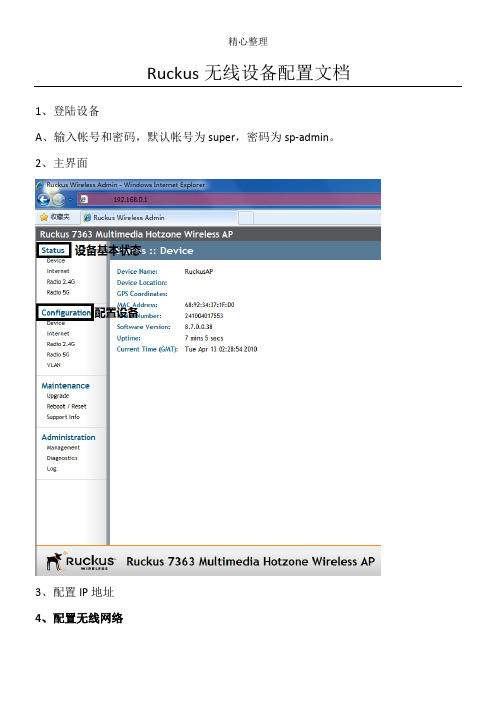
Ruckus无线设备配置文档1、登陆设备A、输入帐号和密码,默认帐号为super,密码为sp-admin。
2、主界面3、4、配置IP地址5、配置无线网络A、点击Radio2.4配置2.4G无线网络,一般802.11b/g/n的网卡只能用2.4G无线网络,市场上99%以上的无线网卡都可以使用。
Radio5G的配置和Radio2.4的配置相同,但只有支持802.11a/n的无线网卡才能使用。
B、ChannelWidth选择为20时设备变为150M,选择40时设备变为300M。
C、其余选项保持默认,完成后保存配置。
6、配置第一个SSIDA、点击Radio2.4G,再单击wireless1,在WirelessNetwork:中填入SSID说明文字,可不做修改。
B、在WirelessAvailability?选项后选择Enabled开启SSID广播。
C、在EncryptionMethod:选择加密方式,一般选择WPA,比较好不容易被破解。
D、在WPAVersion:后选择WPA-Auto。
E、在WPAAuthentication:选择PSK。
F、在WPAAlgorithm:选择Auto。
G、在Passphrase:后面填入无线网络密码。
7、配置第二个SSID按照上面的方法配置第二个SSID。
8、配置VLANA、单击VLAN后进入VLAN配置界面。
B、第一行为管理VLAN,即设备所配地址所在的VLAN。
C、第二行为SSID1的VLAN配置,即为SSID1上网地址所在的VLAN。
D、第三行为SSID2的VLAN配置,即为SSID2上网地址所在的VLAN。
说明:管理Vlan可以和SSID1,SSID2所在的VLAN不同,用户上网的地址也可以和设备地址不再同一个网段中。
控制器无线连接的说明书
控制器无线连接的说明书一、介绍感谢您选择我们的产品,本说明书将详细介绍如何使用无线连接功能,使您的控制器更加便捷和灵活。
请在使用前仔细阅读本说明书,并按照操作指引进行设置和连接。
二、设置步骤1. 准备工作在开始连接前,请确保您的控制器已经成功连接电源,并处于正常工作状态。
2. 打开无线连接功能在控制器的设置菜单中,找到并点击“无线连接”选项,进入无线连接设置界面。
3. 开启无线连接在无线连接设置界面中,找到“开启无线连接”按钮,点击并等待控制器开启无线连接功能。
此时,控制器会自动搜索附近的可用无线网络。
4. 选择可用网络在搜索到的可用网络列表中,选择您要连接的无线网络,并点击进行连接。
注意确保您已知该网络的安全密码,以便成功连接。
5. 输入密码连接无线网络后,控制器会要求您输入网络的安全密码。
请按照屏幕提示,输入正确的密码,并确认连接。
6. 配置网络在成功连接网络后,您可以继续进行网络配置,例如输入静态IP 地址、DNS设置等。
请按照需要进行相关设置,并保存配置。
7. 连接成功完成上述步骤后,您的控制器即可成功连接无线网络。
您可以通过网络访问控制器,实现远程操作和控制。
三、注意事项1. 确保网络稳定在使用无线连接功能时,请确保您的网络环境稳定,并保持较好的信号质量。
较弱的信号可能会导致连接不稳定或者无法连接。
2. 安全设置为了保护您的网络安全,请在配置网络时设置合适的密码和加密方式,确保他人无法未经授权连接到您的控制器。
3. 更新固件我们建议您定期更新控制器的固件,以获得更好的使用体验和功能支持。
请注意在更新固件前备份您的重要数据。
4. 远程访问使用无线连接功能后,您可以通过互联网远程访问控制器。
但请确保远程访问设置合理,并使用安全的连接方式,以保护您的隐私和数据安全。
四、总结通过本说明书的详细指引,您可以轻松设置和连接您的控制器的无线连接功能。
无线连接能够提供更大的灵活性和便捷性,使您更加方便地控制和管理您的设备。
Ruckus Wireless LAN Controllers配置指南说明书
Software Release 5.2CONFIGURATION GUIDEPart Number: 800-71677-001 Rev BPublication Date: 08 November 2017Copyright Notice and Proprietary InformationCopyright 2017 Brocade Communications Systems, Inc. All rights reserved.No part of this documentation may be used, reproduced, transmitted, or translated, in any form or by any means, electronic, mechanical, manual, optical, or otherwise, without prior written permission of or as expressly provided by under license from Brocade. Destination Control StatementTechnical data contained in this publication may be subject to the export control laws of the United States of America. Disclosure to nationals of other countries contrary to United States law is prohibited. It is the reader’s responsibility to determine the applicable regulations and to comply with them.DisclaimerTHIS DOCUMENTATION AND ALL INFORMATION CONTAINED HEREIN (“MATERIAL”) IS PROVIDED FOR GENERAL INFORMATION PURPOSES ONLY. BROCADE and RUCKUS WIRELESS, INC. AND THEIR LICENSORS MAKE NO WARRANTY OF ANY KIND, EXPRESS OR IMPLIED, WITH REGARD TO THE MATERIAL, INCLUDING, BUT NOT LIMITED TO, THE IMPLIED WARRANTIES OF MERCHANTABILITY, NON-INFRINGEMENT AND FITNESS FOR A PARTICULAR PURPOSE, OR THAT THE MATERIAL IS ERROR-FREE, ACCURATE OR RELIABLE. BROCADE and RUCKUS RESERVE THE RIGHT TO MAKE CHANGES OR UPDATES TO THE MATERIAL AT ANY TIME.Limitation of LiabilityIN NO EVENT SHALL BROCADE or RUCKUS BE LIABLE FOR ANY DIRECT, INDIRECT, INCIDENTAL, SPECIAL OR CONSEQUENTIAL DAMAGES, OR DAMAGES FOR LOSS OF PROFITS, REVENUE, DATA OR USE, INCURRED BY YOU OR ANY THIRD PARTY, WHETHER IN AN ACTION IN CONTRACT OR TORT, ARISING FROM YOUR ACCESS TO, OR USE OF, THE MATERIAL.TrademarksRuckus Wireless, Ruckus, the bark logo, BeamFlex, ChannelFly, Dynamic PSK, FlexMaster, Simply Better Wireless, SmartCell, SmartMesh, SmartZone, Unleashed, ZoneDirector and ZoneFlex are trademarks of Ruckus Wireless, Inc. in the United States and in other countries. Brocade, the B-wing symbol, MyBrocade, and ICX are trademarks of Brocade Communications Systems, Inc. in the United States and in other countries. Other trademarks may belong to third parties.Configuring Ruckus Wireless LAN Controllers to Integrate With Cloudpath 2Part Number: 800-71677-001 Rev BContentsConfiguring the Ruckus Wireless Controllers (4)Set up Cloudpath as an AAA Authentication Server (4)Create AAA Accounting Server (Optional) (6)Run Authentication Test (6)ZoneDirector (6)SmartZone (7)Unleashed (7)Possible Results from Authentication Test (8)Create Hotspot Services (8)Set Up the Walled Garden (ZoneDirector and SmartZone only) (12)Create the Onboarding SSID (12)Create the Secure SSID (15)Select AAA Accounting Server for the WLAN on ZoneDirector Controller (18)Select AAA Accounting Server for the WLAN on SmartZone Controller (19)Configuring Ruckus Wireless LAN Controllers to Integrate With CloudpathPart Number: 800-71677-001 Rev B3Configuring the Ruckus Wireless ControllersThis document describes how to configure the Ruckus ZoneDirector, SmartZone, and Unleashed controllers to integrate with the Cloudpath system, and includes the following steps:•Set up Cloudpath as an AAA Authentication Server•Create AAA Accounting Server (Optional)•Create Hotspot Services•Set Up the Walled Garden•Create the Onboarding SSID•Create the Secure SSIDSet up Cloudpath as an AAA Authentication Server Create AAA authentication and accounting servers for the Cloudpath onboard RADIUS server. The following images show this configuration on the Ruckus ZoneDirector, SmartZone, and Unleashed controllers.FIGURE 1 Create AAA Authentication Server on ZoneDirectorConfiguring Ruckus Wireless LAN Controllers to Integrate With Cloudpath 4Part Number: 800-71677-001 Rev BFIGURE 2Create AAA Authentication Server on SmartZoneFIGURE 3Create AAA Authentication Server on UnleashedEnter the following values for the Authentication Server:1.Name 2.Type = RADIUS 3.Auth Method = PAP 4.IP address = The IP address of the Cloudpath ES.5.Port = 18126.Shared Secret = This must match the shared secret for the Cloudpath ES onboard RADIUS server. (Configuration > RADIUSServer ).Set up Cloudpath as an AAA Authentication ServerConfiguring Ruckus Wireless LAN Controllers to Integrate With Cloudpath Part Number: 800-71677-001 Rev B 5Create AAA Accounting Server (Optional)7.Leave the default values for the remaining fields.Create AAA Accounting Server (Optional)Use the same process to create the AAA Accounting Server.Enter the following values for the Accounting Server:2.Type = RADIUS3.Auth Method = PAP4.IP address = The IP address of the Cloudpath ES.5.Port = 1813NOTEThe Authentication server uses port 1812. The Accounting server uses port 1813.6.Shared Secret = This must match the shared secret for the Cloudpath ES onboard RADIUS server. (Configuration > RADIUSServer)7.Leave the default values for the remaining fields.Run Authentication TestYou can test the connection between the controller and the Cloudpath ES RADIUS server.Follow the instructions for the applicable controller. For the possible results, see Possible Results from Authentication Test.ZoneDirectorAt the bottom of the AAA server page, there is a section called "Test Authentication/Accounting Servers Settings." The Test Against field should be Local Database, as shown below. Enter a test User Name and Password, then click the Test button.Configuring Ruckus Wireless LAN Controllers to Integrate With Cloudpath 6Part Number: 800-71677-001 Rev BFIGURE 4Authentication Test on ZoneDirectorSmartZoneYou are prompted to Test Authentication when you save a configuration for an AAA Authentication server. Enter your credentials, then click the Test button.FIGURE 5Authentication Test on SmartZoneUnleashedEnter the test credentials on the Test Authentication Servers Settings tab, then click the Test button.Run Authentication TestUnleashedConfiguring Ruckus Wireless LAN Controllers to Integrate With Cloudpath Part Number: 800-71677-001 Rev B 7FIGURE 6Authentication Test on UnleashedPossible Results from Authentication TestIf you run the authentication test, you receive get one of these responses:•Failed! Connection timed out •Failed! Invalid username and password •Authentication FailedIf you receive:Failed! Invalid username or passwordThis means that connectivity was established.Create Hotspot ServicesEnter the following values for the Hotspot Service:1.Navigate to: Hotspot Services on ZoneDirector, Hotspot WISPr on SmartZone, or Services > Hotspot Services on Unleashed.Create Hotspot ServicesPossible Results from Authentication TestConfiguring Ruckus Wireless LAN Controllers to Integrate With Cloudpath 8Part Number: 800-71677-001 Rev B the Hotspot Service.FIGURE 7Create Hotspot Service on ZoneDirector Create Hotspot ServicesConfiguring Ruckus Wireless LAN Controllers to Integrate With Cloudpath Part Number: 800-71677-001 Rev B 9FIGURE 8Create Hotspot WISPr on SmartZoneCreate Hotspot ServicesConfiguring Ruckus Wireless LAN Controllers to Integrate With Cloudpath 10Part Number: 800-71677-001 Rev BFIGURE 9Create Hotspot Service on Unleashed3.Point the unauthenticated user to the Cloudpath Enrollment Portal URL , which can be found on the Cloudpath Admin UI Configuration > Workflows page, in the Workflows table.4.Check Redirect to the URL that the user intends to visit .5.Select the Cloudpath RADIUS Authentication Server (ZoneDirector only).6.Enable MAC authentication bypass redirection (ZoneDirector only).7.Select the Cloudpath RADIUS Accounting Server (ZoneDirector only).8.Leave the defaults for the remaining settings. Click OK .Create Hotspot ServicesConfiguring Ruckus Wireless LAN Controllers to Integrate With Cloudpath Part Number: 800-71677-001 Rev B 11Set Up the Walled Garden (ZoneDirector and SmartZone only)Enter the following values for the Walled Garden:1.On the Hotspot Service > Configure page, scroll to the bottom to the Walled Garden section below the Hotspot Serviceconfiguration created in the previous section.FIGURE 10 Walled Garden Configurationfor ZoneDirectorFIGURE 11 Walled Garden Configurationfor SmartZone2.Include the DNS or IP address of the Cloudpath system and Save (or Apply )Create the Onboarding SSIDEnter the following values for the onboarding SSID: the SSID.Set Up the Walled Garden (ZoneDirector and SmartZone only)Configuring Ruckus Wireless LAN Controllers to Integrate With Cloudpath 12Part Number: 800-71677-001 Rev B2.Type=Hotspot Service (WISPr).FIGURE 12 Onboarding SSID Configurationon ZoneDirectorCreate the Onboarding SSIDConfiguring Ruckus Wireless LAN Controllers to Integrate With Cloudpath Part Number: 800-71677-001 Rev B 13FIGURE 13 Onboarding SSID Configurationon SmartZoneCreate the Onboarding SSIDConfiguring Ruckus Wireless LAN Controllers to Integrate With Cloudpath 14Part Number: 800-71677-001 Rev BFIGURE 14 Onboarding SSID Configurationfor Unleashed3.Authentication Option Method=Open (SZ and ZD).4.Encryption Option Method=None (SZ and ZD).5.Select the Hotspot Service created in Task 2.6.Enable Bypass CNA (SZ and ZD).•For ZoneDirector, this setting is at the bottom of the screen in the Bypass Apple CNA Feature section. Check the Hotspot Services box.•For SmartZone, this setting is in the Hotspot Portal Section.7.Select the Cloudpath RADIUS Authentication Server (SmartZone only).8.Select the Cloudpath RADIUS Accounting Server (SmartZone only).9.Leave the defaults for the remaining settings and click OK (or Apply ).Create the Secure SSIDEnter the following values for the secure SSID:1.Name the SSID.2.Type=Standard Usage.3.Authentication Option Method=802.1x EAP .4.Encryption Option Method=WPA2 (not applicable for Unleashed once the 802.1x EAP authentication option method is selected).5.Encryption Option Algorithm=AES (not applicable for Unleashed once the 802.1x EAP authentication option method is selected).6.Select the Cloudpath RADIUS Authentication Server.7.Select the Cloudpath RADIUS Accounting Server (SmartZone only).Create the Secure SSIDConfiguring Ruckus Wireless LAN Controllers to Integrate With Cloudpath Part Number: 800-71677-001 Rev B 158.Leave the defaults for the remaining settings and click OK (or Apply ).FIGURE 15 ConfigureSecure SSID on the ZoneDirector controllerCreate the Secure SSIDConfiguring Ruckus Wireless LAN Controllers to Integrate With Cloudpath 16Part Number: 800-71677-001 Rev BFIGURE 16 ConfigureSecure SSID on the SmartZone controllerCreate the Secure SSIDConfiguring Ruckus Wireless LAN Controllers to Integrate With Cloudpath Part Number: 800-71677-001 Rev B 17FIGURE 17 ConfigureSecure SSID on the Unleashed controllerThe SSIDs are now configured on the wireless LAN controller. When the user connects to the onboarding (open) SSID they are redirected to the Cloudpath web page. When the user successfully completes the enrollment process, they are migrated to the secure SSID.Select AAA Accounting Server for the WLAN on ZoneDirector Controller To use Cloudpath onboard RADIUS Accounting and Connection Tracking, the AAA Accounting server must be selected for the WLAN.NOTERADIUS Accounting and Connection tracking status can be viewed on the Cloudpath system, Configuration > RADIUS Server .Create the Secure SSIDSelect AAA Accounting Server for the WLAN on ZoneDirector ControllerConfiguring Ruckus Wireless LAN Controllers to Integrate With Cloudpath 18Part Number: 800-71677-001 Rev BFIGURE 18Select RADIUS Accounting server for the WLAN on ZoneDirector1.Scroll down to the Advanced Options section for the Secure SSID configured for Cloudpath.2.Expand Advanced Options.3.Select the AAA accounting server previously configured for Cloudpath.4.Leave the defaults for the remaining settings and click OK (or Apply ).Select AAA Accounting Server for the WLAN on SmartZone Controller The AAA accounting server was selected during the Secure SSID configuration. No further action is required. See Figure 13 on page 14.Create the Secure SSIDSelect AAA Accounting Server for the WLAN on SmartZone ControllerConfiguring Ruckus Wireless LAN Controllers to Integrate With Cloudpath Part Number: 800-71677-001 Rev B 19Copyright © 2006-2017. Ruckus Wireless, Inc. 350 West Java Dr. Sunnyvale, CA 94089. USA。
优科无线AP 设置
优科无线AP设置1.将笔记本有线网口手工指定IP地址为192.168.0.200,笔记本用网线连接无线AP的10/100/1000POE口,默认登录地址:192.168.0.1用户名:super 密码:sp-admin(注意:初始配置是针对全新无线AP,若拿到的是用过的可以先恢复出厂,恢复出厂方法:通电状态下用笔尖按住无线AP的重置孔5秒不放,拔掉电源在插电5秒后松开重置按钮,管理IP默认变为192.168.0.1)2.打开浏览器登录3.更改默认登录密码:4.指定DNS,此步骤可以默认即可6.开启DHCP功能5.修改列表中2.4G信息注意:若教室周围有较强的2.4G信号,可以在平板上安装“wifi概观360”软件扫描下周围的无线信号所占用的Channel,然后将我们的设备和周围的Channel错开,2.4G信号Channel选择1、6、11相互间干扰最小。
8.添加2.4G学生信号ChangyanSTU,设置ssid及密码9.修改5G 显示信息Channel可以修改为149-169之间的可选频段(注意:畅言智慧课堂对5G无线信号名称要求为ChangyanTCH开头,密码iFlytek1234)下图的标签位置可以查看5G状态,若为UP状态平板搜不到5G信号(不是所有平板和手机都支持5G操作前可以网上查看配置是否支持5G)可以更改Channel153、157、161测试,也可以把上图的Wireless Availability 先Disabled ,保存后,再点击一次Enabled,保存退出,看是否能搜到信号。
10此处按下图配置port1为外网口,port2设置为云服务器连接口。
(注意:靠近电源口的网口为PORT1,若按下图配置后,切勿将外网线插入PORT2,以免造成学校网络中断)常见故障和其它配置其它设置:1.后期可通过无线登录管理界面打开浏览器输入https://192.168.40.1,出现登录画面输入用户名super,密码sp-admin2.指定外网口IP地址上网按下图设置,进入AP管理界面,选择左侧configuration->Internet,输入的IP地址和DNS为现场网管提供。
Skytech TM R-AF1-1 单功能无线遥控系统说明书
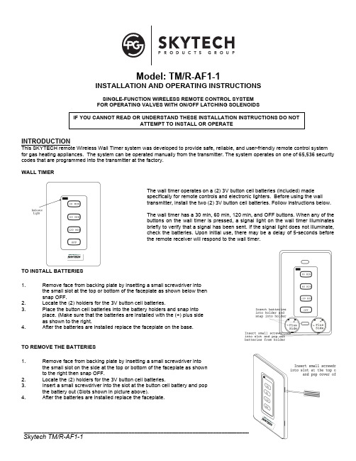
Model: TM/R-AF1-1INSTALLATION AND OPERATING INSTRUCTIONSSINGLE-FUNCTION WIRELESS REMOTE CONTROL SYSTEM FOR OPERATING VALVES WITH ON/OFF LATCHING SOLENOIDSINTRODUCTIONThis SKYTECH remote Wireless Wall Timer system was developed to provide safe, reliable, and user-friendly remote control system for gas heating appliances. The system can be operated manually from the transmitter. The system operates on one of 65,536 security codes that are programmed into the transmitter at the factory.WALL TIMERThe wall timer operates on a (2) 3V button cell batteries (included) made specifically for remote controls and electronic lighters. Before using the wall transmitter, install the two (2) 3V button cell batteries. Follow instructions below.The wall timer has a 30 min, 60 min, 120 min, and OFF buttons. When any of the buttons on the wall timer is pressed, a signal light on the wall timer illuminates briefly to verify that a signal has been sent. If the signal light does not illuminate, check the batteries. Upon initial use, there may be a delay of 5-seconds before the remote receiver will respond to the wall timer.TO INSTALL BATTERIES1. Remove face from backing plate by insetting a small screwdriver into the small slot at the top or bottom of the faceplate as shown below then snap OFF.2. Locate the (2) holders for the 3V button cell batteries.3. Place the button cell batteries into the battery holders and snap into place. (Make sure that the batteries are installed with the (+) plus side as shown to the right.4. After the batteries are installed replace the faceplate on the base.TO REMOVE THE BATTERIES1. Remove face from backing plate by insetting a small screwdriver into the small slot on the side at the top or bottom of the faceplate as shown to the right then snap OFF.2. Locate the (2) holders for the 3V button cell batteries.3. Insert a small screwdriver into the slot at the button cell battery and pop the battery out (Slots shown in picture above).4. After the batteries are installed replace the faceplate.IF YOU CANNOT READ OR UNDERSTAND THESE INSTALLATION INSTRUCTIONS DO NOT ATTEMPT TO INSTALL OR OPERATEWALL MOUNTING THE TIMER 1. Remove face from backing plate by insetting a small screwdriver into the small slot at the top or bottom of the faceplate as shown to the right then snap OFF. 2. Locate the (2) two mounting holes and mark the holes on the wall. 3. Use the (2) two dry wall anchors and screws (that are supplied) to mount the base plate to the wall as shown. 4. The wall transmitter can also be mounted onto an existing (Plastic) electrical box. 5. Base plate should be mounted level on the wall for best operation.REMOTE RECEIVERIMPORTANTTHE REMOTE RECEIVER SHOULD BE POSITIONED WHERE AMBIENTTEMPERATURES DO NOT EXCEED 130° F.The remote receiver (right) operates on (4) 1.5-volt AA batteries. It isrecommended that ALKALINE batteries be used for longer battery life and maximum microprocessor performance. IMPORTANT: New or fully charged batteries are essential to proper operation of the remote receiver as a latchingsolenoid power consumption is substantially higher than standard remote controlsystems.NOTE : The remote receiver will only respond to the transmitter when the 3-position slide button on the remote receiver is in theREMOTE position. The remote receiver houses the microprocessor that responds to commands from the transmitter to control system operation.FUNCTIONS:1. With the slide switch in the REMOTE position, the system will onlyoperate if the remote receiver receives commands from the transmitter. Upon initial use or after an extended period of no use, the ON button may have to be pressed for up to three seconds before activating solenoid. If the system does not respond to the transmitter on initial use, see LEARNING TRANSMITTER TO RECEIVER section. 2. Slide switch to ON for manual operation.3. With the slide in the OFF position, the system is OFF.4. It is suggested that the slide switch be placed in the OFF position ifyou will be away from your home for an extended period of time.Placing the slide switch in the OFF position also functions as a safety "lock out" by both turning the system OFF and rendering the transmitter inoperative.INSTALLATION INSTRUCTIONSWARNINGDO NOT CONNECT REMOTE RECEIVER DIRECTLY TO 110-120VAC POWER. THIS WILLBURNOUTTHE RECEIVER. FOLLOW INSTRUCTIONS FROM MANUFACTURER OF GAS VALVE FOR CORRECT WIRING PROCEDURES. IMPROPER INSTALLATION OF ELECTRIC COMPONENTS CAN CAUSE DAMAGE TO GAS VALVE AND REMOTE RECEIVER.INSTALLATIONThe remote receiver can be mounted on or near the fireplace hearth. PROTECTION FROM EXTREME HEAT IS VERY IMPORTANT. Like any piece of electronic equipment, the remote receiver should be kept away from temperatures exceeding 130º F inside the receiver case. Battery life is also significantly shortened if batteries are exposed to high temperatures.Make sure the remote receiver switch is in the OFF position. For best results it is recommended that 18 gauge stranded wires should be used to make connections and no longer than 20-feet.WIRING INSTRUCTIONSCONNECTING THE RECEIVER TO A VALVE WITH THE LATCHING SOLENOID1. Connect the BLACK 18 gage stranded wire with the 1/4’ female terminal from the receiver to the BLACK wire with the 1/4” maleterminals from the valve solenoid.2. Connect the RED 18 gage stranded wire with the 1/4’ female terminal from the receiver to the RED wire with the 1/4” male terminalsfrom the valve solenoid.3. After receiver wires are connected to the valve solenoid wire make sure the receiver shield is located over the receiver and thenlocate the receiver in an area that will not exceed the 130° F.IMPORTANT NOTE: Operation of these controls is dependent on which wire is attached to which terminal. If operation of controldoes not correspond to operating buttons on transmitter, reverse wire installation at the receiver or at the control.NOTE: Up to 6.3 VDC of power is provided at the receiver terminal.GENERAL INFORMATIONLEARNING TRANSMITTER TO RECEIVEREach transmitter uses a unique security code. It will be necessary to press the LEARN button on the receiver to accept the transmitter security code upon initial use, if batteries are replaced, or if a replacement transmitter is purchased from your dealer or the factory. In order for the receiver to accept the transmitter security code, be sure the slide button on the receiver is in the REMOTE position; the receiver will not LEARN if the slide switch is in the ON or OFF position. The LEARN button in located on the front face of the receiver; inside the small hole labeled LEARN. Using a small screwdriver or end of a paperclip gently Press and Release the black LEARN button inside the hole. When you release the LEARN button the receiver will emit an audible “beep”. After the receiver emits the beep press ANY transmitter button and release. The receiver will emit several beeps indicating that the transmitter’s code has been accepted into the receiver.The microprocessor that controls the security code matching procedure is controlled by a timing function. If you are unsuccessful in matching the security code on the first attempt, wait 1 - 2 minutes before trying again--this delay allows the microprocessor to reset its timer circuitry--and try up to two or three more times.OPERATION4. This remote control will operate the gas valves latching solenoid to open the gas flow to full ON.5. When the ON button is depressed the transmitter sends a RF signal to the receiver. The receiver then sends apulse of 6-volts of power to the solenoid. The solenoid then opens the gas flow to the burner then to full ON.6. When the OFF button is depressed the transmitter sends a RF signal to the receiver. The receiver then sends apulse of 6-volts of power to the solenoid. The solenoid then closes the gas flow to the burner then to full OFF.7. The remote control will only work with the hand held transmitter. The receiver slide switch is only for positive OFF or REMOTEoperation.NOTE: Extensive use of the Latching Solenoid (ON/OFF) will reduce the receiver's battery life significantly.BATTERY LIFELife expectancy of the alkaline batteries in the TM/R-AF1 can be up to 12 months depending on use of the solenoid function. Replace all batteries annually. When the transmitter no longer operates the remote receiver from a distance it did previously (i.e., the transmitter's range has decreased) or the remote receiver does not function at all, the batteries should be checked. It is important that the remote receiver batteries are fully charged, providing combined output voltage of at least 5.0 volts. The transmitter should operate with as little as 2.4 volts battery power. NOTE: Extensive use of the Solenoid will reduce the receiver's battery life significantly.TROUBLE SHOOTINGIf you encounter problems with your fireplace system, the problem may be with the fireplace itself or it could be with the TM/R-AF1 remote system. Review the fireplace manufacturer's operation manual to make sure all connections are properly made. Then check the operation of the remote in the following manner:1. Make sure the batteries are correctly installed in the RECEIVER. One reversed battery will keep receiver from operating properly.2. Check battery in TRANSMITTER to ensure contacts are touching (+) and (-) ends of battery. Bend metal contacts in for tighter fit.3. Be sure RECEIVER and TRANSMITTER are within 20 to 25-foot operating range.4. Keep RECEIVER from temperatures exceeding 120° F. Battery life shortened when ambient temperatures are above 115° F.5. If RECEIVER is installed in tightly enclosed metal surround, the operating distance will be shortened.NOTE:1. Heat conditions can cause batteries to discharge when temperatures exceed 1150 F. Studies show that alkaline batteries, whenexposed to a constant temperature of 1200 F, can lose up to 50% of their operating power. When the battery cools down, it will partially recharge itself, but constant heating and cooling will reduce the battery’s normal life expectancy. SPECIFICATIONSBATTERIES: Transmitter 12V - (A23)Remote Receiver 6V - 4 ea. AA 1.5 Alkaline FCC ID No.'s: transmitter - K9LTMR2A; receiver - K9L330IRX Operating Frequency: 303.8 MHZ Canadian ISC ID No.'s: transmitter – 2439A-TMR2A; receiver – 2439A 3301RX FCC REQUIREMENTSNOTE: THE MANUFACTURER IS NOT RESPONSIBLE FOR ANY RADIO OR TV INTERFERENCE CAUSED BY UNAUTHORIZED MODIFICATIONS TO THIS EQUIPMENT. SUCH MODIFICATIONS COULD VOID THE USER’S AUTHORITY TO OPERATE THE EQUIPMENT.FOR TECHNICAL SERVICE, CALL: U. S. INQUIRIES CANADIAN INQUIRIES(855) 498-8324 or (260) 459-1703 (877) 472-3923For Sales: (888) 672-8929WEBSITE: MANUFACTURED EXCLUSIVELY FOR SKYTECH II, Inc。
无线控制器简易配置手册
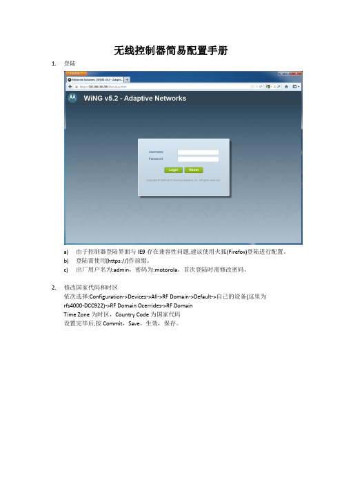
无线控制器简易配置手册1.登陆a)由于控制器登陆界面与IE9存在兼容性问题,建议使用火狐(Firefox)登陆进行配置。
b)登陆需使用[https://]作前缀。
c)出厂用户名为:admin,密码为:motorola。
首次登陆时需修改密码。
2.修改国家代码和时区依次选择:Configuration->Devices->All->RF Domain->Default->自己的设备(这里为rfs4000-DCC922)->RF Domain Ocerrides->RF DomainTime Zone为时区,Country Code为国家代码设置完毕后,按Commit,Save。
生效,保存。
注意:a)国家代码必须选择,并按Commit生效。
为选择国家,控制器上做的一切配置都不会生效!3.添加/修改WLAN设置a)添加WLAN依次选择:Configuration->Wireless->Wireless LANs按右下角的’Add’可添加新的WLAN按’Add’后,会跳转到WLAN设置页。
输入WLAN号、SSID后,按OK才可以进行进一步操作。
b)修改密码/加密模式单击’Security’,在’Select Encryption’项目中勾选需要的加密模式,在’Key Settings’中按要求填入密码(注:不同加密模式的密码填入框会有区别),按’OK’保存配置.按’Commit’,’Save’,生效,保存。
4.AP设置在Configuration->Profiles的左下角,Configuration->Devices->Device Configuration中均可看到所有已上线的设备,可双击进行单个AP配置,或在Profile中选择拥有AP型号的default-apxxxx进行统一配置(注:AP300的配置在Configuration->Devices->AP300 Devices 中)。
- 1、下载文档前请自行甄别文档内容的完整性,平台不提供额外的编辑、内容补充、找答案等附加服务。
- 2、"仅部分预览"的文档,不可在线预览部分如存在完整性等问题,可反馈申请退款(可完整预览的文档不适用该条件!)。
- 3、如文档侵犯您的权益,请联系客服反馈,我们会尽快为您处理(人工客服工作时间:9:00-18:30)。
Ruckus Wireless™
ZoneDirector
配置指导手册
一、仪表盘——查看系统运行情况及日志信息
二、监控——监控系统运行情况
三、配置
3.1系统配置,配置AC的IP地址
3.2WLAN配置
WLAN配置(无线SSID)点击新建创建一个新的SSID,点击编辑对当前SSID进行相应设置
3.3新建WLAN
3.4高级选项
3.5接入点配置
3.6编辑接入点
四、来宾访问
4.1新建来宾接入服务
4.2来宾通行证生成
4.3新建WLAN,类型选择“来宾访问”
4.4配置来宾通行证生成管理用户名与密码4.4.1配置角色
4.4.2配置用户
证生成管理页面
来宾通行证生成-------单个生成
来宾通行证生成-------多个生成
五、终端登录界面
PC端
移动终端。