4, Initial_Configuration
installation

Installation, Initial Configuration, and Platform TroubleshootingModule Objectives☐After completing this module, you will be able to:◆List the important chassis installation issues◆Describe the boot sequence for Juniper Networks routers◆Perform initial configuration◆Describe software upgrade packages and how to back-up existingrouter software◆Describe the difference between jinstall and jbundle, and explain wheneach is needed◆Use show commands to troubleshoot and monitor the router’soperation◆Configure and view system logs◆Describe the location and handling of core files◆Recover lost passwordsGetting the Router Up and Running☐Where we are going…◆Chassis installation◆Power up and power down◆Visible activity at startup◆Boot devices and media◆Boot sequence◆Troubleshooting◆Initial configurationChassis Installation☐AXI 520/580-series product weight◆Typical AXI 580 weighs 300 pounds (135 kg)◆Typical AXI 520 weighs 220 pounds (100 kg)◆Typical AXI 520-4 weighs 120 pounds (53 kg)◆Lifting requires three or more people☐Remove heavier components before lifting◆Power supplies◆FPCs◆Fan trays☐Lift into rack◆Do not lift AXI 520 by Routing Engine handles ☐Replace componentsPower Up and Power Down☐Power up◆Connect all cables◆Turn on one power supply◆Turn on second power supply☐Power down◆Shutdown JUNOS Internet software●CLI request system halt command◆Turn off power suppliesVisible Activity at Startup☐AXI 520, 520-4, 520e, 580, 590 Craft Interface displays:◆Starting Routing Engine◆Starting Packet Forwarding Engine◆Starting PICs☐FPC LEDs◆Blink green while testing◆Become solid green when tests pass☐Alarm LEDs illuminate as neededBoot Devices and Media☐Three media types:◆Removable media●Used for install and upgrade, normally left empty●AXI 520: 120 MB high-capacity floppy drive●All other AXI 520/580-series: 110 MB PCMCIA flash card◆Flash drive●Solid-state nonrotating media●Primary source for booting software◆Hard drive●Traditional rotating media●Secondary source for booting softwareBoot Sequence☐Hardware controlled◆Software notifies hardware when boot completesSuccess?Removable MediaHaltDoneYesNoPrimary Boot Media Secondary Boot MediaSuccess?Solid-State Flash DriveDoneYesNoSuccess?Hard DriveDoneYesNoTroubleshooting☐Craft Interface◆Red LEDs indicate failure◆AXI 520/AXI 580 LCD displays all major and minor alarms ☐Syslog messages◆Contain more detailed information●CLI show log messages command☐CLI◆Interactive failure analysis using show commands◆Monitor log files using monitor commandInitial Configuration☐Upon installation, you should configure:◆Root account●Root is the only pre-defined account●Root password NOT set at factory●Must use console to configure root password◆Host name◆Management interface IP address and prefix length◆Default router IP address◆Domain name and DNS server address◆Remote Access◆User Accounts◆Time☐Log in as rootamnesiac (ttyd0)login: rootLast login: date on ttyd0Copyright (c) 1980, 1983, 1986, 1988, 1990, 1991, 1993, 1994The Regents of the University of California. All rights reserved.---JUNOS 4.4R1 built 2000-07-24 09:29:44 UTC#☐Start CLI# cliroot@amnesiac>☐Enter configuration moderoot@amnesiac> configure[edit]root@#☐Set root password◆Plain textroot@amnesiac# set system root-authentication plain-text-password◆Pre-encrypted passwordroot@amnesiac# set system root-authentication encrypted-password encrypted-password◆Secure Shell (SSH) keyroot@amnesiac#set system root-authentication ssh-rsa key☐Set router name[edit]root@amnesiac#set system host-name lab2☐Set router domain name[edit]root@amnesiac#set domain-name ☐Commit changes so far[edit]root@# commitcommit complete[edit]root@lab2#☐Set management Ethernet IP address and prefix[edit]root@lab2# set interfaces fxp0 unit 0 family inet address ip-address/prefix-length☐Set default route[edit]root@lab2# set system backup-router gateway-address ☐Set name server address[edit]root@lab2# set system name-server ns-address☐Set remote access[edit]root@lab2# set system services ssh☐Set user accounts◆Use predefined login class or create your own◆Configure user name and password[edit system]login {user philip {full-name “Philip of Macedonia”;uid 1001;class superuser;authentication {encrypted-password “$1$poPPeY”;}}☐Configuring time◆Set date and time with set date YYYYMMDDhhmm.ss◆Set Time Zone with set time-zone time-zone◆Configure NTP[edit system]ntp {authentication-key number type type value password;boot-server address;broadcast address key key-number version value ttlvalue;broadcast-client;multicast-client address;peer address key key-number version value<prefer>;server address key key-number version value<prefer>;trusted-key [ key-numbers];}Software Upgrades and Installation☐Where we are going…◆Software installation◆Software upgrade packages◆Package naming convention◆Upgrade software using jbundle◆Backup existing software◆jinstall vs. jbundle◆Upgrade software using jinstall◆Reinstalling JUNOS software from removable media◆Creating image on removable media◆Password recovery process☐Preinstalled from factory onto:◆Flash drive◆Hard drive (alternate copy)◆Removable LS-120 floppy or PCMCIA flash card (use as a last resort)☐Can boot from alternate copy◆If flash drive fails, router can still boot from hard drive or removablemedia●Booting from removable media reformats the hard disk-usewith caution☐Upgrading◆Upgrade packages available through the Internet or on removablemedia☐Software updates◆JUNOS software updates are contained in these packages●jkernel:operating system●jbase:additions to the operating system●jroute:Routing Engine software●jpfe:Packet Forwarding Engine software●jdocs:on-line documentation●jcrypto:security software (in domestic software only)●jbundle:all upgrade packages combined●jinstall-to:upgrade or downgrade to/from 5.0◆Packages can be upgraded individually, but are upgraded most oftentogether with jbundle◆CLI show system software command displays installed packagesPackage Naming Convention☐Software packages have standard namesnumber.tgz◆m.n is the major version number◆Z is a single uppercase letter●A–Alpha●B–Beta●R–Release●I–Internal◆number is the release number, which might include the build numberfor that release◆For example: jbundle-4.4R1.2.tgzUpgrade Software Using jbundle☐Download current package from software download page at: ◆Add new package and store on hard driveroot@lab2> request system software add new-package-name rebootChecking available free disk space...11200k available,6076k suggested.◆Reboot router (if reboot switch not included when software wasadded)root@lab2> request system rebootInstallation Sanity Check☐Incoming software is validated against the current configuration◆Catch potential configuration issues during a software downgraderequest system software add package-name validaterequest system software validate package-namelab@sanjose> ...lidate jbundle-5.3B3.2-domestic-signed.tgzChecking compatibility with configurationInitializing...Using /packages/jbase-5.3R1.2Using /var/home/lab/jbundle-5.3R1.2-domestic-signed.tgzVerified MD5 checksum of /var/validate/tmp/jbundle/jbundle-5.3R1.2-domestic.tgzUsing /var/validate/tmp/jbundle-signed/jbundle-5.3R1.2-domestic.tgz Using /var/validate/tmp/jbundle/jbase-5.3R1.2.tgzUsing /var/validate/tmp/jbundle/jkernel-5.3R1.2.tgzUsing /var/validate/tmp/jbundle/jcrypto-5.3R1.2.tgzUsing /var/validate/tmp/jbundle/jpfe-5.3R1.2.tgzUsing /var/validate/tmp/jbundle/jdocs-5.3R1.2.tgzUsing /var/validate/tmp/jbundle/jroute-5.3R1.2.tgzValidating against /config/juniper.confBack Up Existing Software☐System software and configuration can be backed up to rotating disk. Best used:◆Before major upgrade to ensure system recovery if necessary◆After upgrade when system is judged to be stable☐CLI request system snapshot command◆When booted from the flash drive, this command copies the flash driveenvironment to the rotating disk◆When booted from the rotating disk, this command copies the hard diskenvironment to the router’s flash memory☐Can also direct hard drive to mirror contents of flash with the mirror flash on disk statement◆You cannot issue the request system snapshot command whenyou enable flash disk mirroringjinstall versus jbundle☐When to use jinstall◆Upgrade any Release 4 to any Release 5◆Downgrade any Release 5 to any Release 4☐When to use jbundle◆ 4.x to 4.y or 5.x to 5.y◆ 4.xRx to 4.xRy or 5.xRx to 5xRy☐Downgrading might be two-step processReinstalling JUNOS from Removable Media☐Reinstall JUNOS software if storage media fails or is corrupted◆Future major software revisions might require a full installation ☐Three steps◆Prepare to reinstall JUNOS software◆Reinstall JUNOS software◆Configure JUNOS software☐Preparation◆Record basic information●Router name●Management interface IP address and prefix length●Default router IP address●Domain name and DNS server IP address◆Copy existing configuration file to a safe place on the network●Located in /config/juniper.conf●Full installation erases both flash and rotating drives◆Locate your Juniper Networks installation media●LS-120 floppy or PCMCIA card contains entire JUNOSsoftware distribution☐Final steps◆Insert installation media into Routing Engine●AXI 520—LS-120 floppy●All others—PCMCIA flash card◆Reboot router●Use the CLI from the serial console: root@lab2>requestsystem halt●Power-cycle router◆Follow prompts●System reboots automatically after installation completes◆Restore original configuration●Configure management port and copy original configuration(FTP/SCP)●Use load override termi nal to paste configuration usingthe console portUpdating Removable Media☐Updating process◆FTP the image to the router’s /var/tmp directory, and insertremovable media into the router’s drive◆Escape to the shell and type su to become a super user, if notalready in the super-user class◆Change to the /var/tmp directory, and issue the followingcommands (example is for PCMCIA media v4.x):root@router% dd if=/dev/zero of=/dev/rwd4count=20root@router% tar xzOf 4.4R2.3-export.pcm110.tgz | dd of=/dev/rwd4 bs=64k◆See the Software Download website for LS-120 syntaxMonitoring the Router’s Operation☐Where we are going…◆user@host> show chassis…: displays informati on about thechassis components●FPCs●PICs●FEB, SCB, SFM, SSB●Fans●Power supplies◆user@host> show system…: displays i nformation about thesoftware processes◆user@host> show log…: displa ys information in the log file specified●Default log file is messages●Various daemons write to specific log files (for example,chassisid and sampled)Display Chassis InventoryDisplays chassis inventoryuser@host> show chassis hardwareHardware inventory:Item Version Part number Serial number DescriptionChassis 20824 M40Backplane REV 02 710-001348 AB6500Maxicab REV 07 710-000229 AC7313Minicab REV 01 710-001739 AD3777Display REV 08 710-000150 AC1216SCB REV 03 710-001061 AB0484 Internet Processor IIFPC 0 REV 01 710-001292 AC5304PIC 0 REV 03 750-000611 AA3974 4x OC-3 SONET, MM PIC 1 REV 03 750-000612 AD4885 2x OC-3 ATM, MMListing Alarm ConditionsLists conditions that have triggered alarmsuser@host> show chassis alarms1 alarm is currently activeAlarm time Class Description2001-05-09 21:30:07 UTC Major Power Supply B not providing powerDisplaying Environmental Information Displays environmental information about chassisuser@host>show chassis environmentClass Item Status MeasurementPower Power Supply A OKPower Supply B FailedTemp FPC Slot 0 OK 25 degrees C / 77 degrees F FEB OK 26 degrees C / 78 degrees FPS Intake OK 21 degrees C / 69 degrees FPS Exhaust OK 24 degrees C / 75 degrees F Fans Left Fan 1 OK Spinning at normal speed Left Fan 2 OK Spinning at normal speedLeft Fan 3 OK Spinning at normal speedLeft Fan 4 OK Spinning at normal speedMisc Craft Interface OKDisplaying Contents of LCD Display user@host>show chassis craft-interfaceRed alarm: LED on, relay onYellow alarm: LED off, relay offHost OK LED: OnHost fail LED: OffFPCs 0----------Green *Red .LCD screen:+--------------------+|SanFran ||1 Alarm active ||R: Supply B FAIL |+--------------------+System Controller Board Status☐show chassis (feb|scb|sfm slot|ssb slot)◆Displays information about the system controller boards (either FEB, SCB, SFM, or SSB) user@host>show chassis febFEB status:Temperature 26 degrees C / 78 degrees FCPU utilization 1 percentInterrupt utilization 0 percentHeap utilization 16 percentBuffer utilization 44 percentTotal CPU DRAM 64 MbytesInternet Processor II Version 1, Foundry IBM, Part number 9 Start time: 2001-05-09 17:31:52 UTCUptime: 27 days, 1 hour, 25 minutes, 9 secondsDisplaying FPC StatusDisplays status of installed FPCsuser@host>show chassis fpcFPC status:Temp CPU Utilization (%) Memory Utilization (%) Slot State (C) Total Interrupt DRAM (MB) Heap Buffer0 On-line 35 1 0 8 0 21 On-line 34 65 0 8 0 22 On-line 32 2 0 8 0 23 Unknown 0 0 0 0 0 04 Probed 33 1 0 8 0 25 Unknown 0 0 0 0 0 06 Unknown 0 0 0 0 0 07 Unknown 0 0 0 0 0 0Displaying a Specific FPC’s StatusDisplays detailed view of an FPCuser@host>show chassis fpc detail 0Slot 0 information:State OnlineLogical slot 0Temperature 26 degrees C / 78 degrees FTotal CPU DRAM 8 MbytesTotal SRAM 1 MbytesTotal SDRAM 128 MbytesTotal notification SDRAM 24 MbytesI/O Manager ASIC information Version 2.0, Foundry IBM, Part number 0 Start time: 2001-05-29 21:25:02 UTCUptime: 8 days, 1 hour, 39 minutes, 19 secondsDisplaying PIC Status Displays information for all PICs or for PICs in a particular slot user@host>show chassis fpc pic-statusSlot 0 OnlinePIC 0 4x OC-3 SONET, MMPIC 1 2x OC-3 ATM, MMSlot 1 OnlinePIC 0 1x OC-12 SONET, SMIRPIC 2 1x G/E, 1000 BASE-SXSlot 2 OnlinePIC 1 4x OC-3 SONET, SMIRPIC 2 2x OC-3 ATM, SMIRPIC 3 4x T3Displaying Routing Engine Status Displays information about the Routing Engineuser@host> show chassis routing-engineRouting Engine status:Temperature 29 degrees C / 84 degrees FDRAM 768 MbytesCPU utilization:User 0 percentBackground 0 percentKernel 0 percentInterrupt 0 percentIdle 100 percentStart time 2001-05-29 21:23:33 UTCUptime 8 days, 1 hour, 44 minutes, 58 seconds Load averages: 1 minute 5 minute 15 minute0.04 0.02 0.00Displaying System ProcessesDisplays information and status of all system software processesuser@host> show system processes extensivelast pid: 7090; load averages: 0.06, 0.01, 0.00 06:55:4828 processes: 1 running, 27 sleepingMem: 47M Active, 5516K Inact, 16M Wired, 8350K Buf, 182M FreeSwap: 528M Total, 64K Used, 528M FreePID USERNAME PRI NICE SIZE RES STATE TIME WCPU CPU COMMAND 7088 root 2 0 1704K 788K select 0:00 0.04% 0.04% mgd220 root 2 0 3888K 3332K select 19:37 0.04% 0.04% rpd7090 root 32 0 596K 720K RUN 0:00 0.00% 0.00% top3 root 28 0 0K 12K psleep 0:00 0.00% 0.00% vmdaemon4 root 28 0 0K 12K update 1:52 0.00% 0.00% update173 root 18 0 332K 532K pause 0:03 0.00% 0.00% cron 212 root 18 0 204K 76K pause 0:05 0.00% 0.00% watchdog35 root 10 0 512M 16344K mfsidl 0:00 0.00% 0.00% mount_mfs1 root 10 0 632K 332K wait 0:00 0.00% 0.00% init [additional process list]Displaying Boot MessagesDisplays system boot messagesuser@host> show system boot-messagesCopyright (c) 1992-1998 FreeBSD Inc.Copyright (c) 1996-2000 Juniper Networks, Inc.All rights reserved.Copyright (c) 1982, 1986, 1989, 1991, 1993The Regents of the University of California. All rights reserved. JUNOS 4.4R1.5 #0: 2001-04-20 04:48:50 UTC.[additional boot messages].fxp0: Ethernet address 00:a0:a5:12:12:82fxp1: Ethernet address 00:a0:a5:12:12:81swapon: adding /dev/wd1s1b as swap deviceAutomatic reboot in progress.../dev/rwd0s1a: clean, 26738 free (106 frags, 3329 blocks, 0.1% fragmentation) /dev/rwd0s1e: clean, 17298 free (10 frags, 2161 blocks, 0.1% fragmentation) /dev/rwd0s1a: clean, 26738 free (106 frags, 3329 blocks, 0.1% fragmentation) /dev/rwd1s1f: clean, 7103768 free (504 frags, 887908 blocks, 0.0% fragmentationDisplaying System StatisticsDisplays system-wide protocol-related statistics for packets processed by the Routing Engine user@host> show system statisticsip:476559 total packets received0 bad header checksums0 with size smaller than minimum0 with data size < data length0 with header length < data size[additional protocol information]icmp: ...tcp: ...udp: ...igmp: ...arp: ...Displaying System StorageDisplays amount of storage available on flash and rotating disksuser@host> show system storageFilesystem 1K-blocks Used Avail Capacity Mounted on/dev/ad0s1a 65687 26494 33939 44% /devfs 16 16 0 100% /dev//dev/vn1 9270 9270 0 100% /packages/mnt/jbase/dev/vn2 1448 1448 0 100%/packages/mnt/jcrypto5.0R1.4/dev/vn3 764 764 0 100% /packages/mnt/jdocs-5.0R1.4 /dev/vn4 8392 8392 0 100%/packages/mnt/jkernel5.0R1.4/dev/vn5 11400 11400 0 100% /packages/mnt/jpfe-5.0R1.4 /dev/vn6 5698 5698 0 100% /packages/mnt/jroute-5.0R1.4mfs:181 762223 3 701243 0% /tmp/dev/ad0s1e 25263 13 23229 0% /configprocfs 4 4 0 100% /proc/dev/ad1s1f 7156052 233376 6350192 4% /varDisplaying System ConnectionsLists active IP sockets on Routing Engineuser@host> show system connectionsActive Internet connections (including servers)Proto Recv-Q Send-Q Local Address Foreign Address (state)tcp 0 0 10.0.0.1.21 10.0.0.5.1148 ESTABLISHED tcp 0 0 192.168.0.1.2605 10.0.16.1.179 ESTABLISHED tcp 0 0 *.179 *.* LISTENtcp 0 0 *.79 *.* LISTENtcp 0 0 *.22 *.* LISTENtcp 0 2 10.0.0.1.23 10.0.0.5.1146 ESTABLISHED udp 0 0 *.123 *.*udp 0 0 *.161 *.*[additional information]Displaying Port NumbersWhat is that port number? Pipe to match to simplify your searchuser@host> file show /etc/services# Network services, Internet style## Note that it is presently the policy of IANA to assign a single well-known # port number for both TCP and UDP; hence, most entries here have two entries # even if the protocol doesn't support UDP operations.# Updated from RFC 1700, ``Assigned Numbers'' (October 1994). All ports# are included.# WELL KNOWN PORT NUMBERS#rtmp 1/ddp #Routing Table Maintenance Protocoltcpmux 1/tcp #TCP Port Service Multiplexertcpmux 1/udp #TCP Port Service Multiplexernbp 2/ddp #Name Binding Protocolcompressnet 2/tcp #Management Utilitycompressnet 2/udp #Management Utilitycompressnet 3/tcp #Compression Process---(more)---Displaying System UptimeDisplays system and protocol uptimeuser@host> show system uptimeCurrent time: 2001-08-29 20:28:23 UTCSystem booted: 2001-08-20 01:37:26 UTC (1w2d 18:50 ago) Protocols started: 2001-08-20 01:37:51 UTC (1w2d 18:50 ago)Last configured: 2001-08-22 05:40:43 UTC (1w0d 14:47 ago) by lab 8:28PM up 9 days, 18:51, 2 users, load averages: 0.00, 0.01, 0.00Restarts selected process, for example the routing protocol daemonuser@host> restart ?Possible completions:gracefully Gracefully restart the daemonimmediately Immediately restart (SIGKILL) the daemon interface-control Interface processmib-process SNMP MIB-II processrouting Routing protocol processsampling Traffic sampling control processsnmp SNMP processsoft Soft reset (SIGHUP) the daemonuser@host> restart routingRouting protocol daemon started, pid 1539Restarts the systemuser@host> request system rebootReboot the system ? [yes,no] (no) yesshutdown: [pid 1542]Shutdown NOW!Shutting Downuser@host>request system haltHalt the system ? [yes,no] (no) yesshutdown: [pid 4616]Shutdown NOW!*** FINAL System shutdown message from root@host *** System going down IMMEDIATELYFeb 16 10:25:26 init: alarm-control (PID 300) terminated by signal number 15!. . .rdp keepalive expired, connection dropped -src 0:1020 dest 2:2049if_pfe_listener: soreceive() mute, error 64Feb 16 10:25:31 init: routing (PID 4232) terminated by signal number 9!syncing disks... 3 2 doneThe operating system has halted.Please press any key to reboot.Displaying the Software VersionDisplays host name and release information about the software running on the routeruser@host> show versionHostname: hostModel: m40JUNOS base [4.4R1.5] (Export restricted edition)JUNOS Kernel Software Suite [4.4R1.5]JUNOS Routing Software Suite [4.4R1.5]JUNOS Packet Forwarding Engine Support [4.4R1.5]JUNOS Online Documentation Files [4.4R1.5]KERNEL 4.4R1.5 #0 built by builder on 2001-04-20 04:48:50 UTC.[additional version information].jkernel-dd release 4.4R1.5 built by builder on 2001-04-20 04:44:53 UTC jroute-dd release 4.4R1.5 built by builder on 2001-04-20 05:12:45 UTC jdocs-dd release 4.4R1.5 built by builder on 2001-04-20 05:20:31 UTCMonitoring Traffic☐Monitoring traffic◆Provides CLI-based access to tcpdump utility◆Only displays traffic originating or terminating on local RElab@host> monitor traffic ?Possible completions:<[Enter]> Execute this commandabsolute-sequence Display absolute TCP sequence numbersbrief Show brief outputcount Number of packets to receive (0..1000000 packets) detail Display detailed outputextensive Display extensive outputinterface Monitor traffic on a given interfacematching Receive packets whose headers match this expression no-domain-names Don't display the domain portion of host names no-resolve Don't attempt to print addresses symbolicallyno-timestamp Don't print a timestamp on each dump lineprint-ascii When printing in hex, print in ASCII tooprint-hex Print each packet in hexsize Receive the given number of bytes for each packet (bytes)| Pipe through a command。
微机(Microchip)EV96C70A 55W双输出转换器操作手册说明书

EV96C70A 55W Dual Output Converter from 36V–54V Input EVB IntroductionThis document provides the description and operating procedures for Microchip's dual output 55V/30W and 5V/25W board from 36V–54V input EV96C70A. This board type is used for evaluating the performance of Microchip PoE systems and the Microchip PWM controller LX7309, which is an integral part of Microchip PoE PD controllersPD70201 and PD70211.Microchip’s PD70201 and PD70211 devices are a part of a family of devices that support the IEEE® 802.3af, IEEE 802.3at, and HDBaseT standards PD interface.The PD interface includes the following family of devices.Table 1. Microchip Powered Device Products OfferingsMicrochip’s EV96C70A evaluation board provides designers with the environment needed for evaluating the performance and implementation of PoE PD applications.The board uses two PWM LX7309, which are an integral part of Microchip PD controllers PD70201 and PD70211. This document provides all necessary procedures and instructions to install and operate this board.Figure 1. EV96C70A Block DiagramThe board can be powered through an input connector J6 by a lab supply or by an output of PoE PD front end. See section 1.3. Electrical Characteristics for the input voltage range. The external load is connected to the evaluation board using the J1 (5V/25W) and J7 (55V/30W) output connectors. The following figure shows the location of input and output connectors.D5 is the 55V indication LED and D9 is the 5V indication LED. These LEDs indicate the presence of the corresponding outputs.The following figure shows a top view of the evaluation board.Figure 2. EV96C70A Evaluation BoardTable of Contents Introduction (1)1. Product Overview (4)1.1. Evaluation Board Features (4)1.2. Evaluation Board Connectors (4)1.3. Electrical Characteristics (5)2. Installation (6)2.1. Initial Configuration (6)3. Schematic (7)4. Bill of Materials (9)5. Board Layout (16)6. Ordering Information (20)7. Revision History (21)The Microchip Website (22)Product Change Notification Service (22)Customer Support (22)Microchip Devices Code Protection Feature (22)Legal Notice (22)Trademarks (23)Quality Management System (24)Worldwide Sales and Service (25)1. Product OverviewThis section provides the product overview of the evaluation board.1.1 Evaluation Board Features•Input DC voltage connector and two output voltage connectors.•Onboard “output present” LED indicators.•36 V DC to 54 V DC input voltage range.•Evaluation board working temperature: 0 ℃ to 70 ℃.•RoHS compliant.1.2 Evaluation Board ConnectorsThe following table lists the evaluation board connectors.Table 1-1. Connector Details1.2.1 Input ConnectorThe following table lists pinout of input connector.Table 1-2. J1 Connector•Manufacturer: On Shore Technology.•Manufacturer part number: ED700/2.1.2.2 Output ConnectorsAn external load is connected to the evaluation board using the J1 and J7 output connectors. The following tables list pinouts of the output connector.The manufacturer and manufacturer part number details of the J1 and J7 output connectors are as follows:•Manufacturer: Kaifeng Electronic.•Manufacturer part number: KF350V-02P-14.Table 1-3. J1 ConnectorTable 1-4. J7 Connector1.3 Electrical CharacteristicsThe following table lists the electrical characteristics of the EV96C70A evaluation board.Table 1-5. Electrical CharacteristicsInstallation 2. InstallationThis section provides information about the installation procedure of the EV96C70A evaluation board.Note: Ensure that power source of the board is turned OFF before all peripheral devices are connected.2.1 Initial ConfigurationPerform the following steps for initial configuration:1.Connect load to the board (using J1 and J7).2.Connect a DC supply to input connector J6.3.Turn ON the DC supply.Schematic 3.l4. Bill of MaterialsThe following table lists the bill of materials.Table 4-1. Bill of MaterialsNote: Third-party components can be replaced by approved equivalents. N.C = not installed (optional).5. Board LayoutThis section describes the layout of the evaluation board. This is a four-layer board with 2 Oz copper. The following figures show the silk of the board for tracking devices placements.Figure 5-1. Top SilkFigure 5-4. Bottom CopperOrdering Information 6. Ordering InformationThe following table lists the evaluation board ordering information.Table 6-1. Evaluation Board Ordering InformationRevision History 7. Revision HistoryThe Microchip WebsiteMicrochip provides online support via our website at /. This website is used to make files and information easily available to customers. Some of the content available includes:•Product Support – Data sheets and errata, application notes and sample programs, design resources, user’s guides and hardware support documents, latest software releases and archived software•General Technical Support – Frequently Asked Questions (FAQs), technical support requests, online discussion groups, Microchip design partner program member listing•Business of Microchip – Product selector and ordering guides, latest Microchip press releases, listing of seminars and events, listings of Microchip sales offices, distributors and factory representativesProduct Change Notification ServiceMicrochip’s product change notification service helps keep customers current on Microchip products. Subscribers will receive email notification whenever there are changes, updates, revisions or errata related to a specified product family or development tool of interest.To register, go to /pcn and follow the registration instructions.Customer SupportUsers of Microchip products can receive assistance through several channels:•Distributor or Representative•Local Sales Office•Embedded Solutions Engineer (ESE)•Technical SupportCustomers should contact their distributor, representative or ESE for support. Local sales offices are also available to help customers. A listing of sales offices and locations is included in this document.Technical support is available through the website at: /supportMicrochip Devices Code Protection FeatureNote the following details of the code protection feature on Microchip products:•Microchip products meet the specifications contained in their particular Microchip Data Sheet.•Microchip believes that its family of products is secure when used in the intended manner, within operating specifications, and under normal conditions.•Microchip values and aggressively protects its intellectual property rights. Attempts to breach the code protection features of Microchip product is strictly prohibited and may violate the Digital Millennium Copyright Act.•Neither Microchip nor any other semiconductor manufacturer can guarantee the security of its code. Code protection does not mean that we are guaranteeing the product is “unbreakable”. Code protection is constantly evolving. Microchip is committed to continuously improving the code protection features of our products. Legal NoticeThis publication and the information herein may be used only with Microchip products, including to design, test,and integrate Microchip products with your application. Use of this information in any other manner violates these terms. Information regarding device applications is provided only for your convenience and may be supersededby updates. It is your responsibility to ensure that your application meets with your specifications. Contact yourlocal Microchip sales office for additional support or, obtain additional support at /en-us/support/ design-help/client-support-services.THIS INFORMATION IS PROVIDED BY MICROCHIP "AS IS". MICROCHIP MAKES NO REPRESENTATIONSOR WARRANTIES OF ANY KIND WHETHER EXPRESS OR IMPLIED, WRITTEN OR ORAL, STATUTORYOR OTHERWISE, RELATED TO THE INFORMATION INCLUDING BUT NOT LIMITED TO ANY IMPLIED WARRANTIES OF NON-INFRINGEMENT, MERCHANTABILITY, AND FITNESS FOR A PARTICULAR PURPOSE, OR WARRANTIES RELATED TO ITS CONDITION, QUALITY, OR PERFORMANCE.IN NO EVENT WILL MICROCHIP BE LIABLE FOR ANY INDIRECT, SPECIAL, PUNITIVE, INCIDENTAL, OR CONSEQUENTIAL LOSS, DAMAGE, COST, OR EXPENSE OF ANY KIND WHATSOEVER RELATED TO THE INFORMATION OR ITS USE, HOWEVER CAUSED, EVEN IF MICROCHIP HAS BEEN ADVISED OF THE POSSIBILITY OR THE DAMAGES ARE FORESEEABLE. TO THE FULLEST EXTENT ALLOWED BY LAW, MICROCHIP'S TOTAL LIABILITY ON ALL CLAIMS IN ANY WAY RELATED TO THE INFORMATION OR ITS USE WILL NOT EXCEED THE AMOUNT OF FEES, IF ANY, THAT YOU HAVE PAID DIRECTLY TO MICROCHIP FOR THE INFORMATION.Use of Microchip devices in life support and/or safety applications is entirely at the buyer's risk, and the buyer agrees to defend, indemnify and hold harmless Microchip from any and all damages, claims, suits, or expenses resulting from such use. No licenses are conveyed, implicitly or otherwise, under any Microchip intellectual property rights unless otherwise stated.TrademarksThe Microchip name and logo, the Microchip logo, Adaptec, AnyRate, AVR, AVR logo, AVR Freaks, BesTime, BitCloud, CryptoMemory, CryptoRF, dsPIC, flexPWR, HELDO, IGLOO, JukeBlox, KeeLoq, Kleer, LANCheck, LinkMD, maXStylus, maXTouch, MediaLB, megaAVR, Microsemi, Microsemi logo, MOST, MOST logo, MPLAB, OptoLyzer, PIC, picoPower, PICSTART, PIC32 logo, PolarFire, Prochip Designer, QTouch, SAM-BA, SenGenuity, SpyNIC, SST, SST Logo, SuperFlash, Symmetricom, SyncServer, Tachyon, TimeSource, tinyAVR, UNI/O, Vectron, and XMEGA are registered trademarks of Microchip Technology Incorporated in the U.S.A. and other countries. AgileSwitch, APT, ClockWorks, The Embedded Control Solutions Company, EtherSynch, Flashtec, Hyper Speed Control, HyperLight Load, IntelliMOS, Libero, motorBench, mTouch, Powermite 3, Precision Edge, ProASIC, ProASIC Plus, ProASIC Plus logo, Quiet- Wire, SmartFusion, SyncWorld, Temux, TimeCesium, TimeHub, TimePictra, TimeProvider, TrueTime, WinPath, and ZL are registered trademarks of Microchip Technology Incorporated in the U.S.A.Adjacent Key Suppression, AKS, Analog-for-the-Digital Age, Any Capacitor, AnyIn, AnyOut, Augmented Switching, BlueSky, BodyCom, CodeGuard, CryptoAuthentication, CryptoAutomotive, CryptoCompanion, CryptoController, dsPICDEM, , Dynamic Average Matching, DAM, ECAN, Espresso T1S, EtherGREEN, GridTime, IdealBridge, In-Circuit Serial Programming, ICSP, INICnet, Intelligent Paralleling, Inter-Chip Connectivity, JitterBlocker, Knob-on-Display, maxCrypto, maxView, memBrain, Mindi, MiWi, MPASM, MPF, MPLAB Certified logo, MPLIB, MPLINK, MultiTRAK, NetDetach, NVM Express, NVMe, Omniscient Code Generation, PICDEM, , PICkit, PICtail, PowerSmart, PureSilicon, QMatrix, REAL ICE, Ripple Blocker, RTAX, RTG4, SAM-ICE, Serial Quad I/O, simpleMAP, SimpliPHY, SmartBuffer, SmartHLS, SMART-I.S., storClad, SQI, SuperSwitcher, SuperSwitcher II, Switchtec, SynchroPHY, Total Endurance, TSHARC, USBCheck, VariSense, VectorBlox, VeriPHY, ViewSpan, WiperLock, XpressConnect, and ZENA are trademarks of Microchip Technology Incorporated in theU.S.A. and other countries.SQTP is a service mark of Microchip Technology Incorporated in the U.S.A.The Adaptec logo, Frequency on Demand, Silicon Storage Technology, Symmcom, and Trusted Time are registered trademarks of Microchip Technology Inc. in other countries.GestIC is a registered trademark of Microchip Technology Germany II GmbH & Co. KG, a subsidiary of Microchip Technology Inc., in other countries.All other trademarks mentioned herein are property of their respective companies.© 2022, Microchip Technology Incorporated and its subsidiaries. All Rights Reserved.ISBN: 978-1-5224-9978-7Quality Management SystemFor information regarding Microchip’s Quality Management Systems, please visit /quality.Worldwide Sales and Service。
Dell EMC NX440 系统设置指南说明书

• Your system is configured with a default system name of D<ServiceTag>, where <ServiceTag> is the Service Tag.
• To locate the Service Tag of your system, see the section Locating your system Service Tag in this document.
Starting remote desktop
NOTE: Make sure that you have completed the Initial Configuration tasks before connecting to the NAS system using remote desktop.
network settings. You can start remote desktop from a client and remotely access the NAS system using either the default system name or the IP address. For example, in the Remote Desktop Connection dialog box, type D<ServiceTag>, where <ServiceTag> is the Service Tag. To locate the Service Tag of your system, see the section Locating your system Service Tag in this document. NOTE: The default password is Stor@ge!
Dell PowerVault 网络连接存储 (NAS) 系统 故障排除指南说明书

Dell™ PowerVault™Network Attached Storage(NAS) 系统故障排除指南注、小心和警告注:“注”表示可以帮助您更好地使用计算机的重要信息。
小心:“小心”表示如果不遵循说明,就有可能损坏硬件或导致数据丢失。
警告:“警告”表示可能会造成财产损失、人身伤害甚至死亡。
____________________本说明文件中的信息如有更改,恕不另行通知。
©2010Dell Inc.版权所有,翻印必究。
未经 Dell Inc. 书面许可,严禁以任何形式复制这些材料。
本文中使用的商标:Dell、DELL徽标、 PowerEdge、PowerVault和 OpenManage 是 Dell Inc. 的商标;Microsoft和Windows是 Microsoft Corporation 在美国和/或其它国家和地区的商标或注册商标。
本说明文件中述及的其它商标和产品名称是指拥有相应商标和产品名称的公司或其制造的产品。
Dell Inc. 对其它公司的商标和产品名称不拥有任何所有权。
2010 年 4 月修订版 A00目录安装问题 (5)部署问题 (10)管理问题 (12)更新问题 (15)目录34目录安装问题表 1.安装问题问题说明临时解决 / 解决方案在替换了硬盘驱动器或重安装了操作系统之后,附随 RAID 5 的系统配置默认为RAID 1 配置。
或在操作系统重安装之后系统上的 RAID 配置与原始出厂配置不匹配。
如果操作系统重安装DVD 无法在磁盘 0 上找到 80 GB 或更大的操作系统分区,则会默认为RAID1 配置。
要解决此问题,请执行以下步骤:注:操作系统仅可安装在内部控制器的 LUN 0 上。
要配置不同于 RAID 1 的 RAID 配置,在重安装操作系统之前创建一个带有LUN ID 0 的虚拟磁盘。
1如果可能,请备份在虚拟磁盘上的所有数据。
2重引导系统然后输入 Dell™PowerEdge™ RAID controller(PERC) BIOS。
jedisconnectionconfiguration lookup method -回复

jedisconnectionconfiguration lookup method-回复Jedis Connection Configuration: A Comprehensive GuideIntroduction:In the world of distributed systems and scalable applications, a key component is the ability to connect and interact with various data stores and backend systems efficiently. One popular choice for connecting to the Redis data store is Jedis, a Java client library that provides a simple and intuitive interface for accessing Redis. In this article, we will dive deep into the internals of Jedis connection configuration, focusing on the lookup method and its significance.Understanding Jedis Connection Configuration:Jedis connection configuration plays a critical role in establishing a connection to the Redis server and managing related settings. It acts as a bridge between the application and the Redis server, allowing seamless communication and interaction.The lookup method is a fundamental part of the Jedis connectionconfiguration. It is responsible for resolving the connection parameters required to establish a connection with the Redis server. Let's explore the lookup method in detail:1. Initial Configuration:The first step in establishing a connection is to define the initial configuration for Jedis. This includes specifying the Redis server host, port, and other relevant connection parameters. The lookup method is invoked at the beginning of the connection setup process to fetch this initial configuration.2. Configuration Resolution:After fetching the initial configuration, the lookup method performs configuration resolution. This involves evaluating any dynamic properties or system variables that may impact the connection settings. For example, if the Redis server's IP address changes or if there is a need to switch to a different server dynamically, the lookup method identifies and updates the configuration accordingly.3. Connection Pooling and Load Balancing:One of the key features of Jedis is its ability to utilize connection pooling and load balancing for improved performance and scalability. The lookup method is responsible for determining the appropriate connection pool size and load balancing strategy. It takes into account factors such as the number of connections required, server capacity, and network conditions to make an informed decision.4. Failover Handling:Redis servers can experience failures or become unresponsive due to various reasons. The lookup method in Jedis connection configuration detects such failures and performs failover handling. It can be configured to automatically redirect requests to the backup Redis server or handle failover manually based on predefined rules. The lookup method ensures uninterrupted access to the Redis data store even in the event of server failures.5. Timeout and Retry Settings:In distributed systems, network delays and intermittent failures are common. The lookup method allows for setting timeout and retry configurations to handle such scenarios seamlessly. It determines the timeout duration for establishing a connection, executing commands, and reading responses. Additionally, it manages the number of retries and the duration between retries to ensure reliable and robust communication with the Redis server.6. Security and Authentication:To protect sensitive data stored in Redis, authentication mechanisms are often required. The lookup method provides a way to configure and manage authentication settings for connecting to password-protected Redis servers. It securely handles authentication credentials, encrypts communication, and verifies the identity of the Redis server.7. Ongoing Monitoring and Configuration Updates:The Jedis connection configuration is not a one-time setup process. It requires continuous monitoring and configuration updates to adapt to evolving requirements and changing conditions. Thelookup method periodically checks for configuration changes, such as server updates or new Redis instances being added, and applies the necessary adjustments without disrupting ongoing connections.Conclusion:The lookup method in Jedis connection configuration is an essential component that enables seamless, efficient, and reliable communication between applications and Redis servers. It handles resolution of connection parameters, connection pooling, load balancing, failover handling, timeout and retry settings, security, and ongoing monitoring. Understanding and effectively utilizing the lookup method empowers developers to build scalable and performant distributed systems using Jedis and Redis as their data store.。
完整的JMETER使用手册

JMETER中文手册1. 简介Apache JMeter是100%纯java桌面应用程序,被设计用来测试客户端/服务器结构的软件(例如web应用程序)。
它可以用来测试包括基于静态和动态资源程序的性能,例如静态文件,Java Servlets,Java 对象,数据库,FTP 服务器等等。
JMeter可以用来在一个服务器、网络或者对象上模拟重负载来测试它的强度或者分析在不同的负载类型下的全面性能。
另外,JMeter能够通过让你们用断言创建测试脚本来验证我们的应用程序是否返回了我们期望的结果,从而帮助我们回归测试我们的程序。
为了最大的灵活性,JMeter允许我们使用正则表达式创建断言。
1.1 历史Apache软件组织的Stefano Mazzocchi是JMeter的创始人。
他编写它起初是为了测试Apache JServ的性能(一个已经被Apache Tomcat工程所替代的工程)。
我们重新设计JMeter来增强用户界面并增加功能测试的能力。
1.2 未来我们希望看到作为开发者利用它的可插入架构使JMeter的功能快速扩展。
未来发展的主要目标是在没有影响JMeter的负载测试能力的情况下尽可能使JMeter 成为最实用的回归测试工具。
2. 入门开始使用JMeter最容易的方法是首先下载最新版并且安装它。
这个版本包含所有你在构建和运行Web,FTP,JDBC,和JNDI等测试时使用需要的所有文件。
如果你想执行JDBC测试,你当然需要从供应商得到适当的JDBC驱动。
JMeter 没有提供任何JDBC驱动。
你可能需要下载的其它软件:∙BeanShell- BeanShell函数和测试元件需要∙Java Activation Framework- JavaMail需要∙Java Mail- Mail可视化,Mail Reader 和WebService(SOAP)取样器需要∙JMS- JMS 取样器需要∙General Java download page详细参见JMeter Classpath一章安装附加的jar包∙下一步, 开始使用JMeter并且参见用户手册创建一个测试计划一章使自己更加熟悉JMeter基础 (例如,添加和删除元件)。
最初的英语短语

最初的英语短语最初这个词,有多少个英语短语?下面是店铺给大家整理的最初的英语短语,供大家参阅!最初initial的英语短语1Once the excitement, the motivation and the initial momentum subside (and they will), what willkeep you doing what you need to do, to create the change you want to see in your world?人一旦兴奋,动机和最初的动力就会减弱(他们会这样),什么会让你保持做你要做的,去创造出这种在你的世界里你想看到的改变?If this is the initial configuration, the server should not be running .如果这是初始配置,则服务器不应该在运行。
This extends into every aspect of your application, from initial design right down to thedeployment layer.从最初的设计到开发阶段,它们可以延伸到你应用程序的每一个方面。
So the US should set a deadline for the suspension of enrichment. The initial deal should tradesuspension of enrichment for suspension of sanctions.所以美国应该对停止浓缩行为设定一个最后期限.最初的交易是以暂停浓缩铀以换取制裁的中止.I know that all state machines must start in some initial state.我知道,所有状态机必须在某些初始状态下启动。
It has an initial size and a growth parameter.它有一个初始的大小和一个增长参数。
NETGEAR 交换机设置指南说明书
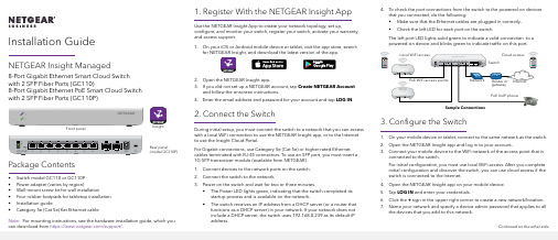
Installation Guide 4. To check the port connections from the switch to the powered-on devicesthat you connected, do the following:• Make sure that the Ethernet cables are plugged in correctly.• Check the left LED for each port on the switch.The left port LED lights solid green to indicate a valid connection to apowered-on device and blinks green to indicate traffic on this port.3. Configure the Switch1. On your mobile device or tablet, connect to the same network as the switch.2. Open the NETGEAR Insight app and log in to your account.3. Connect your mobile device to the WiFi network of the access point that isconnected to the switch.For initial configuration, you must use local WiFi access. After you complete initial configuration and discover the switch, you can use cloud access if the switch is connected to the Internet.4. Open the NETGEAR Insight app on your mobile device.5. Tap LOG IN and enter your credentials.6. Click the + sign in the upper right corner to create a new network/location.7. Name your network and specify a device admin password that applies to allthe devices that you add to this network.NETGEAR Insight Managed8-Port Gigabit Ethernet Smart Cloud Switch with 2 SFP Fiber Ports (GC110)8-Port Gigabit Ethernet PoE Smart Cloud Switch with 2 SFP Fiber Ports (GC110P)Package Contents• Switch model GC110 or GC110P• Power adapter (varies by region)• Wall-mount screw kit for wall installation• Four rubber footpads for tabletop installation• Installation guide• Category 5e (Cat 5e) flat Ethernet cable 1. Register With the NETGEAR Insight AppUse the NETGEAR Insight App to create your network topology, set up, configure, and monitor your switch, register your switch, activate your warranty, and access support.1. On your iOS or Android mobile device or tablet, visit the app store, searchfor NETGEAR Insight, and download the latest version of the app.2. Open the NETGEAR Insight app.3. If you did not set up a NETGEAR account, tap Create NETGEAR Accountand follow the onscreen instructions.4. Enter the email address and password for your account and tap LOG IN. 2. Connect the SwitchDuring initial setup, you must connect the switch to a network that you can access with a local WiFi connection to use the NETGEAR Insight app, or to the Internet to use the Insight Cloud Portal.For Gigabit connections, use Category 5e (Cat 5e) or higher-rated Ethernet cables terminated with RJ-45 connectors. To use an SFP port, you must insert a1G SFP transceiver module (available from NETGEAR).1. Connect devices to the network ports on the switch.2. Connect the switch to the network.3. Power on the switch and wait for two or three minutes.• The Power LED lights green, indicating that the switch completed its startup process and is available on the network.• The switch receives an IP address from a DHCP server (or a router that functions as a DHCP server) in your network. If your network does notinclude a DHCP server, the switch uses 192.168.0.239 as its default IPaddress.Sample Connections Front panelRear panel(model GC110P)InsightNote: For mounting instructions, see the hardware installation guide, which youcan download from https:///support/.Continued on the other side.NETGEAR, Inc.350 East Plumeria DriveSan Jose, CA 95134, USA NETGEAR INTL LTDBuilding 3, University Technology Centre Curraheen Road, Cork, Ireland© NETGEAR, Inc., NETGEAR and the NETGEAR Logo are trademarks of NETGEAR, Inc. Any non‑NETGEAR trademarks are used for reference purposes only.October 20188. Tap NEXT .9. To add the switch to your account, use one of these options:• Enter the serial number.• Scan the serial number bar code.•Tap Switch as the device type and follow the prompts to scan the network or scan the QR code.You are prompted to add the switch to a network.10. Either select a network or create a new one.11. When prompted, name the switch.The switch automatically updates to the latest firmware (if needed). This might take several minutes. When the blue Cloud LED lights on the switch, you can begin configuring it.Other Configuration MethodsYou can also use the NETGEAR Insight Cloud Portal to set up your network and manage your devices as well as your subscription. A Premium subscription is required to use the Insight Cloud Portal. (A limited time, free trial is included with 24-port and larger Insight switch purchases.) When using the Insight Cloud Portal, the configuration steps are the same except that you manually enter the serial number of the device when prompted. For more information on NETGEAR Insight, visit https:///#/login .For more information about how to connect a NETGEAR Insight managed switch to an existing network, visit https:///000044341.Note: We do not recommend using the switch’s local browser–basedmanagement interface to configure the switch offline. Changes made using this method are not pushed to the cloud, so they are not reflected in the NETGEAR Insight app or the Insight Cloud Portal, and might create conflicts with the Insight-managed network to which the switch is connected. If you cannotconnect your switch to a network with Internet access, and you want to use the local-only browser interface to access the switch, see the user manual.To download the user manual, visit /support/product/GC110 or /support/product/GC110P .If you cannot discover or configure the switch, you might need to temporarily disable the firewall, Internet security, or antivirus programs. Make sure to reenable these security services after discovering and configuring the switch.PoE Troubleshooting for Model GC110PHere are some tips for correcting simple problems that might occur:•Make sure that the PoE Max LED is off. The switch provides a total power budget of 62 watts. If the PoE Max LED is solid amber, disconnect one or more powered devices (PDs) to prevent PoE oversubscription. Start by disconnecting the PD from the highest-numbered port.Note: You can manually override the amount of power that is reserved for each PoE port and attached PD by using the NETGEAR Insight app or the Insight Cloud Portal. •Check the right LED for the port on the switch that is connected to apowered PD. The right port LED on the switch lights solid green to indicate that PoE is being delivered to the PD. If the right port LED lights solid amber, a PoE fault occurred.SupportThank you for purchasing this NETGEAR product. You can visit/support to register your product, get help, access the latest downloads and user manuals, and join our community. We recommend that you use only official NETGEAR support resources.Si ce produit est vendu au Canada, vous pouvez accéder à ce document en français canadien à https:///support/download/.(If this product is sold in Canada, you can access this document in Canadian French at https:///support/download/.)For regulatory compliance information including the EU Declaration of Conformity, visit https:///about/regulatory/.See the regulatory compliance document before connecting the power supply.Do not use this device outdoors. If you connect cables or devices that are outdoors to this device, see https:///000057103 for safety and warranty information.。
- 1、下载文档前请自行甄别文档内容的完整性,平台不提供额外的编辑、内容补充、找答案等附加服务。
- 2、"仅部分预览"的文档,不可在线预览部分如存在完整性等问题,可反馈申请退款(可完整预览的文档不适用该条件!)。
- 3、如文档侵犯您的权益,请联系客服反馈,我们会尽快为您处理(人工客服工作时间:9:00-18:30)。
8
Initial Configuration Checklist
Have the following information ready when performing the initial setup through the CLI or the EZsetup option:
•Hostname (optional) •Root password •System time (optional) •Details regarding how the switch will be accessed for management (in band or out of band, and VLAN assignment) •Management interface and default gateway IP addresses •Remote access protocols to be used (Telnet, SSH) •SNMP contact and community information (optional)
•Remember to commit!
[edit] user@switch# rollback rescue load complete [edit] user@switch# commit commit complete [edit] user@switch#
Activates rescue configuration
There might be times when you want to return to a factory configuration Use the load factory-default configuration command and set a root password:
©2008 Juniper Networks, Inc. All rights reserved.
6
Factory-Default Configuration
Enables family ethernet-switching for all ports Enables default system logging Enables LLDP and RSTP Enables PoE on all supported ports Loads one-time factory-settings option
©Hale Waihona Puke 008 Juniper Networks, Inc. All rights reserved.
4
Saving a Rescue Configuration
Two methods of saving rescue configuration:
• request system configuration rescue save CLI command •J-Web Maintain > Config Management > Rescue option
3
Rescue Configuration
A rescue configuration is designed to restore basic connectivity in the event of configuration problems
•The user defines the contents
• Include a root password!
•By default, there is no rescue configuration •Save rescue configuration using J-Web or the CLI •Retrieve with rollback rescue CLI command •View with file show/config/rescue.conf.gz CLI command
Saves current active configuration as rescue configuration.
©2008 Juniper Networks, Inc. All rights reserved.
5
Loading the Rescue Configuration
Retrieve the rescue configuration by using the rollback rescue CLI configuration-mode command
…
©2008 Juniper Networks, Inc. All rights reserved.
11
Initial Configuration Using J-Web EZsetup (1 of 2)
Easy deployment option for new switches
•Boot switch with factory-default configuration •Navigate the LCD menu and select Enter EZsetup •Connect laptop or PC to ge-0/0/0 •Point Web browser to http://192.168.1.1
Activates the factory-default configuration
Navigate the LCD menu by pressing the menu button and choose Restore to Factory Default
©2008 Juniper Networks, Inc. All rights reserved.
Installation and Initial Configuration
4-1
Copyright © 2005 Juniper Networks, Inc. Proprietary and Confidential
General Installation Guidelines
©2008 Juniper Networks, Inc. All rights reserved.
13
Initial Configuration Using the CLI (1 of 6)
Log in as root with a null password
Amnesiac (ttyu0) login: root
Amnesiac prompt indicates a factory-default configuration
--- JUNOS 9.1R2.10 built 2008-07-01 04:34:43 UTC root@%
Start the CLI
UNIX shell prompt
root@% cli root>
•Initiated using the LCD menu
CLI
•Manually configure the switch using the JUNOS CLI
©2008 Juniper Networks, Inc. All rights reserved.
10
Initial Configuration Using Console EZsetup
Obtain console connection to switch Enter ezsetup from the shell prompt
Amnesiac (ttyu0) login: root Password: --- JUNOS 9.1R2.10 built 2008-07-01 04:34:43 UTC root@% ezsetup Initial Setup Configuration --------------------------Enter System hostname [Optional]:switch Enter new root password: Re-enter the new password: Enable Telnet service? [yes|no]. Default [yes]:
Rebooting the system with the LCD menu:
•System reboot option under Maintenance mode
Automatic power-on feature
©2008 Juniper Networks, Inc. All rights reserved.
©2008 Juniper Networks, Inc. All rights reserved.
12
Initial Configuration Using J-Web EZsetup (2 of 2)
EZsetup in J-Web automates initial management configuration options
2
Power On and Power Off
JUNOS software is a multitasking environment
•A graceful shutdown of the operating system ensures file system integrity
• Use the J-Web Maintain > Reboot page or the request system halt CLI command to gracefully halt JUNOS software • Power is maintained to the system; reboot with console activity
[edit] user@switch# load factory-default warning: activating factory configuration [edit] user@switch# set system root-authentication plain-text-password New password: Retype new password: [edit] user@switch# commit commit complete