精密空调维修手册s[1]
艾美康精密空调维修手册

艾美康精密空调维修手册摘要:一、前言二、精密空调概述1.精密空调的定义2.精密空调的作用三、精密空调的组成结构1.压缩机2.冷凝器3.膨胀阀4.蒸发器5.风机四、精密空调的维修流程1.维修前准备2.故障排查3.故障维修4.维修后的检查五、精密空调的常见故障及处理方法1.压缩机故障2.冷凝器故障3.膨胀阀故障4.蒸发器故障5.风机故障六、精密空调的维护保养1.日常维护2.定期检查3.清洁保养七、结语正文:【前言】艾美康精密空调维修手册旨在为用户提供一个详细的维修指南,帮助用户了解精密空调的组成结构、维修流程以及常见故障处理方法。
通过本手册,用户可以更好地对精密空调进行维护保养,确保设备的正常运行。
【精密空调概述】精密空调是一种具有高精度、高可靠性的空调设备,广泛应用于通信、电子、医疗等领域。
其主要作用是提供恒温、恒湿、洁净的空气环境,以保证设备或物品的性能和寿命。
【精密空调的组成结构】精密空调主要由压缩机、冷凝器、膨胀阀、蒸发器和风机等部件组成。
这些部件相互配合,共同完成空调的制冷、制热、加湿、除湿等功能。
【精密空调的维修流程】精密空调的维修流程包括维修前准备、故障排查、故障维修和维修后的检查。
在维修前,需要对设备进行充分了解,并准备好相应的工具和材料。
故障排查是找出设备存在的问题,有针对性地进行维修。
维修过程中应遵循安全操作规程,确保设备不受损坏。
维修后,应对设备进行检查,确认故障已排除,设备正常运行。
【精密空调的常见故障及处理方法】精密空调的常见故障包括压缩机故障、冷凝器故障、膨胀阀故障、蒸发器故障和风机故障等。
针对不同故障,应采取相应的处理方法。
例如,对于压缩机故障,需要检查压缩机的工作电流、压力和噪音等参数,找出问题所在并进行修复或更换。
【精密空调的维护保养】为了确保精密空调的正常运行,需要进行定期的维护保养。
日常维护包括观察设备运行状况、清洁设备表面和保持设备周围环境整洁。
定期检查主要是对设备的各项参数进行检查,确保其在正常范围内。
精密空调日常维护维修
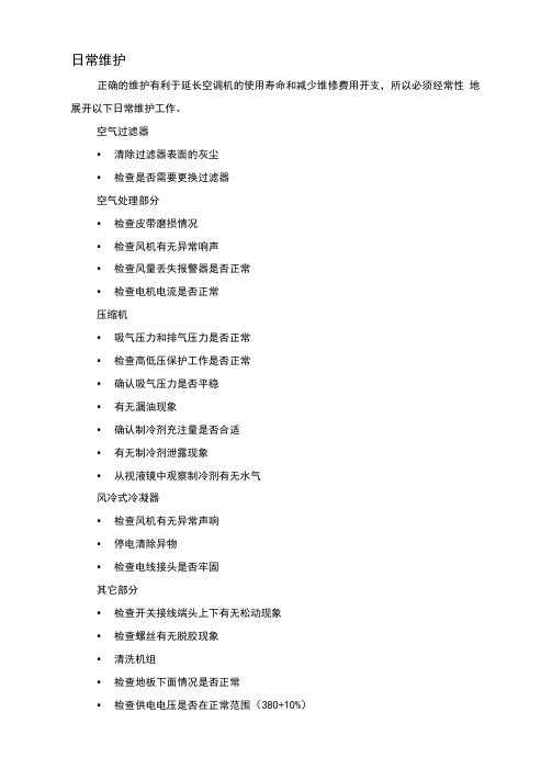
日常维护正确的维护有利于延长空调机的使用寿命和减少维修费用开支,所以必须经常性地展开以下日常维护工作。
空气过滤器•清除过滤器表面的灰尘•检查是否需要更换过滤器空气处理部分•检查皮带磨损情况•检查风机有无异常响声•检查风量丢失报警器是否正常•检查电机电流是否正常压缩机•吸气压力和排气压力是否正常•检查高低压保护工作是否正常•确认吸气压力是否平稳•有无漏油现象•确认制冷剂充注量是否合适•有无制冷剂泄露现象•从视液镜中观察制冷剂有无水气风冷式冷凝器•检查风机有无异常声响•停电清除异物•检查电线接头是否牢固其它部分•检查开关接线端头上下有无松动现象•检查螺丝有无脱胶现象•清洗机组•检查地板下面情况是否正常•检查供电电压是否在正常范围(380+10%)•切换电源时,要注意相序一致•加湿器供水应保持清洁,出水管道要畅通•加湿器要注意除垢•保持室内气流畅通9. 2维修工具1常用工具2十字螺丝刀;一字螺丝刀3钳子:鲤鱼钳:尖嘴钳:钢丝钳:封口钳4扳手:梅花扳手;套筒扳手各一套;活动扳手5铿刀:圆铿;平铿:三角锤:什锦铿一套6锤子:铁榔头:木榔7温度计8专用设备和工具⑴制冷剂(R22)⑵三通修理阀⑶真空泵⑷气焊设备⑸管子割刀⑹扩管器⑺弯管器⑻电烙铁⑼万用表(10)钳形电流表(1D兆欧表⑫测漏仪9.3 故障分析及处理Denco空调机常见报警内容:1.High/Low Room Temperature2.High/Low Room Humidify (室温过高/低)(室内湿度过高/3.HP Circuit 14.HP Circuit 25.LP Circuit 16.LP Circuit 27.Airflow Fail9.Kli Xion10.Dirty Filter11.Hum Lack of current (1号压缩机高压)(2号压缩机高压)(1•号压缩机低压)(2号压缩机低压)(失风,8.气流丢失)(加热器超负荷)(滤网堵塞)(加湿器故障)注:当报警发生时,红色的发光二极管闪烁并且发生蜂鸣声,用静音键可消除蜂鸣声,这时发光二极管报警灯停止闪烁,但仍发亮,表示报警。
空调的维修保养手册

空调的维修保养手册目录1. 介绍2. 维修2.1 常见问题2.2 维修步骤3. 保养3.1 定期清洁3.2 检查电线和插头3.3 检查滤芯3.4 保持通风4. 总结5. 附录1. 介绍本手册为空调的维修保养指南,旨在帮助用户了解如何保持空调设备的正常运行,并解决一些常见的问题。
2. 维修2.1 常见问题在使用空调过程中,可能会遇到以下常见问题:- 空调无法启动- 空调不制冷或制热效果不佳- 空调产生异味或噪音- 空调漏水2.2 维修步骤当您遇到以上问题时,您可以按照以下步骤进行维修:1. 检查电源是否正常连接,并确保电源开关打开。
2. 检查空调的温度设置是否正确。
3. 清理空调内外部的灰尘和杂物。
4. 检查空调的滤芯是否需要更换或清洁。
5. 检查空调的冷凝水管是否堵塞。
6. 如果问题仍然存在,请联系专业的维修人员。
3. 保养保养空调设备可以延长其使用寿命并确保正常运行。
以下是一些常见的保养步骤:3.1 定期清洁定期清洁空调设备可以防止灰尘和杂物堆积,影响空调的散热效果。
您可以使用干净的布或吹尘器清洁空调内外部的表面。
3.2 检查电线和插头定期检查空调设备的电线和插头是否有损坏或松动。
如发现问题,请及时修复或更换,并确保安全使用。
3.3 检查滤芯滤芯是空调设备中的重要组成部分,可以过滤空气中的灰尘和污染物。
定期检查滤芯的清洁程度,如有需要,请更换或清洗。
3.4 保持通风确保空调设备周围有良好的通风,避免堵塞空气流通的通道。
4. 总结通过按照本手册提供的维修保养指南,您可以保持空调设备的正常运行,并解决一些常见的问题。
如果遇到更复杂或严重的问题,建议尽快联系专业的维修人员进行处理。
5. 附录- 常见问题解答- 维修服务联系方式- 相关安全注意事项。
精密空调日常维护使用手册
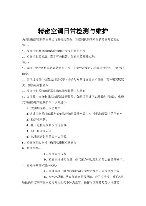
精密空调日常检测与维护
为保证精密空调的正常运行及使用寿命,对空调机的简单维护是非常必要的
每日:
1、检查控制器显示的温度和相对湿度值是否相符;
2、检查控制器记录,查看有关报警,如有报警及时处理;
每月:
1、风机:检查风机马达运转是否正常(有无异常噪声、轴承是否发热),检查耗油量;
2、空气过滤器:检查过滤器状态(必要时对其进行清洁和替换,若环境灰度较大,需要经常检查);
3、检查控制系统的屏幕显示单元和报警工作状态;
4、加湿器:检查电极式加湿器是否结垢,如结垢需拆下加湿器进行清洗。
电极式加湿器罐的更换按如下步骤进行:
1)关闭加湿器上水总开关;
2)通过控制系统的服务菜单执行加湿器排水若干次,排除加湿器中的所有水;
3)松开蒸汽管;
4)松开电极电线和水位传感器;
5)向上松开固定夹
6)从底部密封压盖拔出加湿器。
5、检查电源的各相(确保电路接点紧密);
6、制冷剂循环:
a、检查运行压力;
b、检查压缩机耗电量、排气压力和温度以及是否有异常噪声。
7、室外冷凝器和室外风机:
a、室外风机:检查风机转动有无异常噪声,运行电路正常;
b、室外冷凝器:从底部观察是否已脏,若脏应清洗,拆下风机顺散热片方用高压水枪方向由上向下冲洗盘管,操作时应注意避免损坏盘管。
常见故障排除对应表。
RC集团neXt精密空调安装维护手册

NEXT 系列
RC GROUP S.p.A
...............................................................................................................................................................................4 前言 ......................................................................................................................................................................................5 第一章 概述 ........................................................................................................................................................................6
1.1 质量保证 ................................................................................................................................................................6 1.2 开机调试 .........................................
机房精密空调的日常维护与主要故障处理
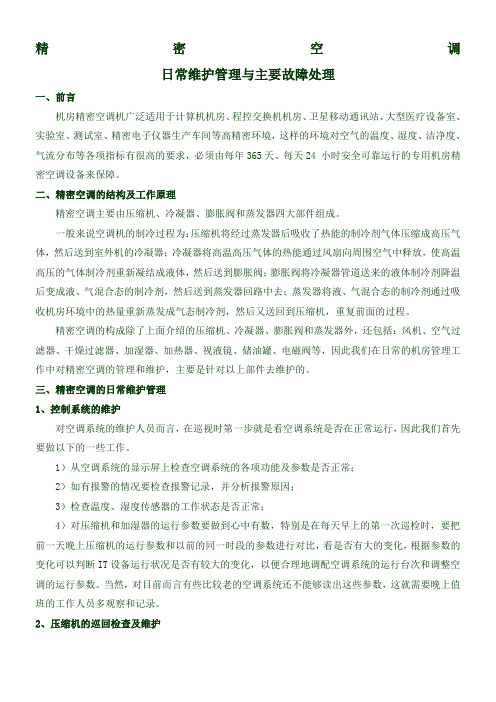
精密空调日常维护管理与主要故障处理一、前言机房精密空调机广泛适用于计算机机房、程控交换机机房、卫星移动通讯站、大型医疗设备室、实验室、测试室、精密电子仪器生产车间等高精密环境,这样的环境对空气的温度、湿度、洁净度、气流分布等各项指标有很高的要求,必须由每年365天、每天24 小时安全可靠运行的专用机房精密空调设备来保障。
二、精密空调的结构及工作原理精密空调主要由压缩机、冷凝器、膨胀阀和蒸发器四大部件组成。
一般来说空调机的制冷过程为:压缩机将经过蒸发器后吸收了热能的制冷剂气体压缩成高压气体,然后送到室外机的冷凝器;冷凝器将高温高压气体的热能通过风扇向周围空气中释放,使高温高压的气体制冷剂重新凝结成液体,然后送到膨胀阀;膨胀阀将冷凝器管道送来的液体制冷剂降温后变成液、气混合态的制冷剂,然后送到蒸发器回路中去;蒸发器将液、气混合态的制冷剂通过吸收机房环境中的热量重新蒸发成气态制冷剂,然后又送回到压缩机,重复前面的过程。
精密空调的构成除了上面介绍的压缩机、冷凝器、膨胀阀和蒸发器外,还包括:风机、空气过滤器、干燥过滤器、加湿器、加热器、视液镜、储油罐、电磁阀等,因此我们在日常的机房管理工作中对精密空调的管理和维护,主要是针对以上部件去维护的。
三、精密空调的日常维护管理1、控制系统的维护对空调系统的维护人员而言,在巡视时第一步就是看空调系统是否在正常运行,因此我们首先要做以下的一些工作。
1)从空调系统的显示屏上检查空调系统的各项功能及参数是否正常;2)如有报警的情况要检查报警记录,并分析报警原因;3)检查温度、湿度传感器的工作状态是否正常;4)对压缩机和加湿器的运行参数要做到心中有数,特别是在每天早上的第一次巡检时,要把前一天晚上压缩机的运行参数和以前的同一时段的参数进行对比,看是否有大的变化,根据参数的变化可以判断IT设备运行状况是否有较大的变化,以便合理地调配空调系统的运行台次和调整空调的运行参数。
当然,对目前而言有些比较老的空调系统还不能够读出这些参数,这就需要晚上值班的工作人员多观察和记录。
山特精密空调一体机架空调用户手册说明书

客服热线:400-830-3938/800-830-3938Rack Type Air Conditioner User Manual 一体机架空调用户手册产品防伪为了切实保障您的用电安全,帮助您购买到真正的山特精密空调,请注意以下事项:1. 认准山特注册商标:、、、、。
2. 山特所有产品机身上均贴有“产品序列号”(产品序列号是唯一的,一个产品对应一个序列号);如果您购买到有疑问的山特产品,可通过以下途径向本公司反馈1.客服热线:400-830-3938/800-830-39382.品牌保护邮箱:*************************版权声明山特公司致力于技术创新,不断提供更好的产品和服务满足客户需求,对产品设计、技术规格的更新,恕不另行通知。
产品以实物为准。
请到山特网站w 下载最新版的产品说明书。
版权所有© 2020山特电子(深圳)有限公司1.1F OREWORD (1)1.2A IR CONDITIONER DESCRIPTION (1)1.2.1Principles of function (1)1.2.2Operating Conditions (1)1.3S TANDARDS (2)2.SAFETY NOTICES (2)3.INSTALLATION AND OPERATION (2)3.1M ECHANICAL INSTALLATION (2)3.2E LECTRICAL INSTALLATION (3)3.3P OWER-ON STEPS (4)4.SYSTEM FUNCTION INTRODUCTION4 4.1C OOLING (4)4.2H EATING (O PTION) (5)4.3D OOR ALARM (5)4.4C OMPONENT CONTROL MODE (5)4.5U NIT SEQUENCING CONTROL (OPTION) (5)4.5.1T IME S WITCHING (5)4.5.2T EMPERATURE SWITCH (5)4.5.3B OTH WORKING WITH HIGH TEMPERATURE (5)4.5.4D ISTURBANCE SWITCHING (5)4.6S ELF TESTING (6)4.7H YDROGEN DISCHARGING/EMERGENCY FAN (OPTION) (6)4.8A LARM (6)4.9U NIT MENU STRUCTURE (7)4.9.1Operation interface (7)4.9.2Menu structure (7)5.MAINTENANCE (8)5.1D AILY MAINTENANCE (8)5.2C OMPRESSOR MAINTENANCE (8)5.3C OMMON FAULT (9)1.简介 (15)1.1前言 (15)1.2空调器描述 (15)1.2.1工作原理 (15)1.2.2运行条件 (15)1.3符合标准 (16)2.安全注意事项 (16)3.安装和操作 (17)3.1空调器机械安装 (17)3.2电气安装 (17)3.3开机步骤 (18)4.系统功能介绍 (18)4.1制冷功能 (19)4.2制热功能(选配) (19)4.3门禁功能 (19)4.4器件控制模式 (19)4.5双机切换控制(选配) (19)4.5.1定时切换 (19)4.5.2温度切换 (19)4.5.3高温同开 (19)4.5.4故障切换 (20)4.6自测 (20)4.7排氢/应急风扇(选配) (20)4.8故障 (20)4.9机组菜单结构 (21)4.9.1操作界面 (21)4.9.2菜单结构 (21)5.维护 (22)5.1日常维护表 (22)日常维护表 (22)5.2压缩机维护 (22)5.3故障及恢复措施 (23)常见故障及恢复措施 . E RROR!B OOKMARK NOT DEFINED.6.产品有毒有害物质申明 (29)附录1.维修保证 (30)附录2.合格证 (31)Introduction1.1 ForewordNote: All of the operations of this product shall be performed by professional engineers and technicians.This manual can only be used to guide the installation and operation of EF series of industry cabinet air-conditioners. The manual content includes the functional description and regular maintenance of the unit. In this manual, the safety tips and warning signs are described as follows:DANGER!If the measures described in the following are not strictly observed there is danger to life and health.HAZARD!If the measures described in the following are not strictly observed there is danger to life and health due to electrical shock.CAUTION!If the measures described in the following are not strictly observed material damage may be caused.1.2 Air conditioner descriptionThe EF series outdoor cabinet air conditioner is a cooling product developed for cabinet. This air conditioner’s frequency can be regulated. It has cooling capacity regulating function, and the fans can regulate speed automatically.Function Diagram 1.2.1 Principles of functionThe refrigerant is compressed by compressor (1) into high temperature and high pressure gas; To the condenser (3), and suctioned by the cooling fan (2) from the bottom part into outdoor air, where the heat is forced through the condenser (3) to spread to the surrounding environment in the air, and the refrigerant becomes into a liquid through the throttling element (4), the refrigerant pressure drops, and in the evaporator (6), the refrigerant absorbs the heat inside the control cabinet and evaporates; The hot air is suctioned by the evaporation fan (5) from inside the control cabinet, and through the evaporator, the air is cool and forced to discharge into the inside of the control cabinet. At the same time, the air inside the control cabinet is dehumidified.This series can be used a variety of installations.This is shown in the pictures below:Working Principle Diagram1.2.2 Operating Conditions⚫Power system220VAC±15%,50/60Hz⚫External cycle temperature:-40℃~ 50℃Note: Please read the nameplate parameters on the air conditioner carefully. The actual technicalparameters shall be subject to the nameplate name.1.3 StandardsStandard DescriptionGB/T17626.7-1998EMCGB4706.1Safety of household appliances or similar electric applianceGB4798.1Environmental conditions existing in the application of electric and electronic product –StorageGB4798.2Environmental conditions existing in the application of electric and electronic product –TransportationGB4798.3Environmental conditions existing in the application of electric and electronic product –Use2. Safety noticesThe following safety notices are to be observed in their entirety for the correct use of the equipment: 2.1 Transport⚫Keep the air conditioner in a horizontal state during transportation.⚫If the cabinet needs to be transported, please remove the air conditioner and pack itseparately before transportation.2.2 Storage⚫Storage environment should not exceed 70 °. ⚫Keep the air conditioner in a horizontal state during storage.2.3 Unpacking⚫Prior to and during unpacking make a visual inspection of the air conditioner to seewhether any damage has occurred duringtransport. Especially pay attention to looseparts,dents,visible loss of oil etc.⚫Any damage mast be reported immediately to the forwarding agent (follow the instructionsin“Rules For Damage Claims”).Moreover,thelatest ed ition of the “After sales Service Letterof Commitment”⚫Before disposing of packing material ensure that it does not contain any loose components.2.4 Installation ⚫The site for the enclosure, and hence the arrangement of the air conditioner, is selected so as to ensure good ventilation;⚫The location is free from excessive dirt and moisture;⚫The ambient temperature does not exceed +45℃;⚫The enclosure is sealed on all sides(IP54).Condensation will occur if the enclosure isleakage;⚫Air inlet and outlet are not obstructed on the inside of the enclosure;⚫The duct size outside the air conditioner cabinet should not be less than the limit value in the following figure.⚫Units are only fitted horizontally in thespecified position.Max. Deviation from the true horizontal:2°;⚫Losses from the components installed in the enclosure must not exceed the specificrefrigeration capacity of the air conditioneritself;⚫The customer must not modify the airconditioner in any way.Distance Diagram3. Installation and Operation3.1 Mechanical installationBefore the installation of air conditioner, the fitting surface of cabinet shall be properly opened withvent and screw hole, where the hole size shall refer to the appearance size figure as provided by the manufacturer.CAUTION!If the required cutouts are only made in the switch cabinet just before mounting of the air conditioner, make sure that swarf is not allowed to enter the device hood by using a cover sheet. Mounting:1) Insert the air conditioner into the cabinet alongthe guide rail direction.2) The installation flange of the air conditionerand the installation surface inside the cabinetare fixed, as shown in the figure below:Installation Diagram3.2 Electrical installationCAUTION!As the cabinet air conditioner is connected to the power supply via the circuit protection device, the appropriate circuit protection device and the power cable should be chosen according to the air conditioning nameplate and technical parameters.CAUTION!Too high voltage may lead to damage of cabinet air conditioner. Please follow the voltage requirement marked on the nameplate to switch on the air conditioner.CAUTION!In order to avoid any damaging effects, before turning on the power supply, the cabinet air conditioner must be reliably earthed.Note: The power input port identifier is subject to the specific unit screenprintingReferences to common (copper wire) selection: RatedCurrent≤5A≤10A≤15A≤25A Power linediameter1.0mm1.5mm2.5mm4mmConnecting interface (The power input terminal will be subject to application instructions)Connecting interface:Port DefinitionPowerinputL1/LL:220VAC power input cable L;L1:110VAC power input cable L L2/NN:220VAC power input cable N;L2:110VAC power input cable L PEGrounding wire of the airconditionerAlarm outputNC The first public alarm dry nod (NC) COMThe first public alarm dry nod(COM)NOThe first public alarm dry nod(NO)(Option)1The second public alarm dry nod(COM)(Option)2The second public alarm dry nod(NO) (Option)Signal input 3 N/A4Hydrogen discharge / emergencyfan dry contact (FG) (Option)5Hydrogen discharge / emergencyfan dry contact (NO) (Option)6Hydrogen discharge / emergencyfan dry contact (COM) (Option) 7Door open alarm input (option)8comm unicati on ports +RS485 communication ports (+)(Option)-RS485 communication ports (-)(Option)⚫Alarm output (option):The unit provides alarm output dry contact. Ifthere is no alarm, the dry contact is close.When there is alarm, the dry contact will open.Contact capacity: resistive load5A@30VDC/5A@250VAC.⚫Hydrogen discharge / emergency fan electricity connecting.(option):Note: Contact capacity: max load 2A@-48VDC; 8A@230VAC.➢Hydrogen discharge / emergency fan(AC input) connecting interface diagram;AC input connecting interface diagram➢Hydrogen discharge / emergency fan(DC input) connecting interface diagram;DC input connecting interface diagramDC input connecting interface diagram(FG:optional)3.3 Power-on stepsFirstly make sure the AC voltage is in accordance with the standard, and then close the power input switch. 30s later the internal cycle fan of the unit will be started. After delay time about 3min, the unit select operation mode according to the unit’s. 4. System function introductionAir conditioner running is automatically controlled completely according to the temperature inside the cabinet, and through the inner loop temperature sensor, the controller detects the cabinet return air temperature and the set point for judgment, to control the work of compressor or the fan.4.1 CoolingCooling stop point=cooling start point-cooling sensitivity. When the cabinet internal temperature exceeds the cooling start-up point, the cooling will be started; when the cabinet internal temperature is lower than the cooling stop point, the cooling Parameter Default value Setting rangeCoolSP 25℃[15~50]Cool△T 5℃[1~10]INHT 65℃[20~80]stops.Setting point description:CoolSP:Point when cooling starts.Cool△T:Temperature control sensitivity.INHT:Internal high Temp. alarm point.CAUTION!For the reliable operation of the unit and the maximum energy efficiency, it is recommended that the users should not randomly change the temperature set point. The above set point is not on behalf of the factory settings.4.2 Heating (Option)Heating stop point=heating point+heating sensitivity. When the temperature inside the cabinet is lower than the heating start-up point, the heating will start; when the temperature inside the cabinet is higher than the heating stop point, the heating will stop.Parameters Default value Setting range HeatSP 0℃[-5~15]Heat△T 10℃[1~15]Setting point description:HeatSP:Point when heating starts.Cool△T:Temperature control sensitivity.CAUTION!For the reliable operation of the unit and the maximum energy efficiency, it is recommended that the users should not randomly change the temperature set point. The above set point is not on behalf of the factory settings.4.3 Door alarmTo avoid an increase in condensation, a door operated switch should be used which will switch the air conditioner off when the switch the air conditioner off when the enclosure door is opened. After judging whether the cabinet door is opening or not by the sign sent by the door magnetic switch ,the air conditioner will alarm and stop. CAUTION:When door opened, the door magnetic switch will be triggered to shut down the air conditioner after one minute. After door closed, the door magnetic switch will be released, then the air conditioner will start work after three minutes when the temperature inside is higher than the set point.4.4 Component control mode1) Control modern of internal fan:The inner fan runs in normal speed when system runs normally.2) Control mode of external fan:Air circulation mode: The external fan stops.Cooling mode:The external fan’s running speed depends on the condenser’s temperature. The higher the temperature is, the higher the fan speed is; the lower the temperature is, the lower the fan speed is.3) Control mode of compressor:Air circulation mode: Compressor stops.Cooling mode: The compressor’s running speed depends on the temperature differences between return air and setting value. The higher the difference is, the higher the compressor speed is; the lower the difference is, the lower the compressor speed is.4.5 Unit sequencing control(option)The equipment has linkage function including time switching, disturbance switching, high temperature switching.4.5.1 Time SwitchingTwo air conditioners switch as setting time.4.5.2 Temperature switch1) When cabinet temp reach the setting point cooling point only one air-con will work. When temp lower than cooling stop point, the air-con stops working.2) When cabinet temp reach the setting point high temp point, two air-cons will work together. When temp lower than (high temp point - sensitivity), one air-con stops working, only one air-con will work alone.4.5.3 Both working with hightemperatureWhen one appears high temperature alarm, the other will work at the same time. If high temperature alarm is cleared, one air conditioner will be closed, it will recover to time and temperature switching status.4.5.4 Disturbance switching1) When one air conditioner has a problem, the other will start immediately.2) If the fault that is come up in the switching time is cleared, it do not switch to other until time switch is finished.3) If the fault is not cleared, the other will work all the time.4.6 Self testingThe unit provides the self testing function for on site test and it will automatically goes to self-testing procedure if choosing self-testing function in the system function menu, the procedures are as below:1) If the compressor doesn’t stop, stop thecompressor.2) The internal fan runs for 60 seconds.3) The external fan runs for 60 seconds.4) The compressor runs for 60 seconds with lowlimit speed, meanwhile the external fan runs with 50% full speed.5) The compressor runs for 60 seconds withupper limit speed, meanwhile the external fan runs with full speed.6) If configured with heater, starts heater andruns for 120s.7) If configured with hydrogen discharging fan,starts the fan and runs for 120s.8) The compressor, internal fan & external fan,electric heater, hydrogen discharging fan stops.9) Self-testing procedures finished, the unit worksaccording to the normal logic.4.7 Hydrogendischarging/emergency fan(option)Discharge hydrogen at regular times: according to the requirement for environment inside the cabinet, the hydrogen discharging fan realizes automatic cycle hydrogen discharging and forced ventilation. The interval time of each automatic cycle hydrogen discharging is 24 hours and the discharging time is 5 minutes.2) Forced ventilation:when the compressor does not have cooling capacity (including compressor failure, power failure), the temperature inside the cabinet is higher than the start up point (emergency point + sensitivity) of emergency fan , start the emergency fan.4.8 AlarmThe cabinet air conditioner provides the following alarm information. Please refer to table for the setting point.Diagram for alarm triggeredIf the alarm hasn’t been recovered, t he alarm information will be still on, until the alarm has been eliminated. And you can check the alarm statistics through entering the alarm menu shown as Figure.Sensor Failure4.9 Unit menu structure4.9.1 Operation interfaceThe unit controller adopts the 96x32 LCD, which contains 7 buttons for the setting. The operation interface is as shown in the following figure:ON/OFF:ON/OFF button (press the button 5s), this can be used to turn on/off the unit.: Up button, which is used to increase the setting value or select the previous record/menu.: Down button, which is used to decrease the setting value or select the next record/menu. 4.9.2 Menu structure: Left button, which is used to select the previous bit of the data.: Right button, which is used to select the next bit of the data.ENTER: ENTER button, which is used to confirm the entry.ESC: Quit button, which is used to return to the previous page menu.If there is no keyboard operation for consecutively 60s under any interface after start-up, it will automatically return to the normal display interface. When any button is pressed after the system is powered up, the backlight will turn on. If there is no keyboard operation for consecutively 60s, the backlight will be off.The factory default operation password of the unit is “0001”. To change it, you need to press ENTER on the normal display interface to enter the password input interface, press the LEFT button or RIGHT button to select the bits for change, and press the UP/DOWN button to change the relevant digits, and finally press ENTER button to confirm the change. If the password is incorrect, the interface will display the error message, and the unit setting cannot be changed. If the password is correct, you can enter the main menu and edit the unit setting.Remarks:InT: Internal return temperature sensorTp: Evaporator coil temperature sensorTe: Compressor exhaust pipetemperature sensorCond: Condenser coil temperaturesensorUnit menu structureNote: This diagram is unit menu structure, not the real factory setting.中文EnglishON/OFF ENTER ESC5. MaintenanceTo ensure the normal operation of the airconditioner, please perform regular maintenance for it by referring to Table 5.1.Hazard!All the maintenance should be performed by qualified professionals. Please disconnect thepower and communication & alarm output cables of the air conditioner before any maintenance and do not reconnect them until the maintenance is completed.5.1 Daily maintenanceDaily maintenance table5.2 Compressor maintenanceWhen the compressor is faulted, the solution is replaced with new unit.DISPOSAL :Do not dispose this product as unsorted municipal waste. Collection of such waste separately for special treatment is necessary.City Trash CanCheck item Step descriptionMaintenance cycle Wiring Visually check if the wiring is looseOne year Fan abnormalities Turn the fan to check if it is smooth and if there is any abnormal noiseOne year Drainage pipe Visually check if the drainage mouth is blockedSix monthsCondenser Check the cleanness of the condenser and clean it with compressed airSix monthsFilterCheck visually and clean. If there is dustaccumulation, it can be blown or washed and driedSix months5.3 Common faultCommon fault and recovery measure.can not work5.4 Charge RefrigerantUnits sold outside mainland China do not contain refrigerant. Please refer to the following operations to charge refrigerant on site.1 Tools PreparationTable 5-1Tools preparationTool Illustration FunctionScrewdriver ⚫Dedicated screwdriver is used to remove the anti-theft screws.⚫Flat-blade screwdriver is used to remove the connecting wire from the controller.⚫Phillips screwdriver is used to remove screws from other parts.Diagonal pliers Used to process cables on site and remove the fixed cable ties. Portable vacuumpumpUsed to vacuum on site.Pressure gauge Used to monitor system pressure, maintain pressure, and charge refrigerant for use.Refrigerant R410A refrigerant.Electronic scale Used to charge refrigerant and monitor the weight of the refrigerant charged. Protective gloves Wear gloves when charging refrigerant and vacuuming.Goggles Used to protect the eyes.2 Disassemble the Unit⚫Figure 5-1Disassemble the unitStep 1 Use a small flat-blade screwdriver to remove the air conditioner power cables (L,N, PE). See A in Error! Reference source not found..Step 2 Use a small flat-blade screwdriver to remove the air conditioner signal lines(RS485+, RS485-). See B in Error! Reference source not found..Step 3 Remove the signal line fixed buckles and the drainage pipe binding ties. See C in Error! Reference source not found..Step 4 Open the front door of the cabinet and use a Phillips screwdriver to remove thefour installation screws of the air conditioner. See D in Error! Reference sourcenot found..Step 5 Grasp the two handles on the front panel of the air conditioner and slowly pull out the air conditioner. See E in Error! Reference source not found..Step 6 Use a flat-blade screwdriver to remove the screws of the upper cover and remove the upper cover. Find the refrigerant charging port, as shown in F in Error!Reference source not found..CAUTIONThe charging port is divided into a high-pressure charging port and a low-pressure charging port, and therefrigerant is charged from the low-pressure port. See G in Error! Reference source not found..3 Charge RefrigerantStep 1 Connect the vacuum pump.Use a pressure gauge to connect the high-pressure charging port (red pipe) and low-pressure charging port (blue pipe) of the air conditioner, and the middle pipe is connected to the vacuum pump.⚫Figure 5-2Connect to the vacuum pump(1) Low pressure gauge (2) High pressure gauge (3) Zero adjustment screw(4) Low pressure valve (5) Sight window (6) High pressure valve(7) Low pressure side interface (8) High pressure side interface (9) Vacuum pump or refrigerantinterfaceStep 2 Use a vacuum pump to vacuum the refrigeration system.After confirming that the pipeline connection is completed, turn on the vacuum pump to start vacuuming. Thevacuum degree of the system is required to be below 35Pa.⚫Figure 5-3Power on the vacuum pumpStep 3 Maintain pressure on the system.After the vacuum is completed, power off the vacuum pump, close all the pressure gauges and tighten theconnection between the pressure gauge and the vacuum pump. Keep the pressure of the system for 20-30 minutes and observe whether the pointer of the pressure gauge does not move. If the value of the pressure gauge needleremains unchanged (maintained at -0.1MPa), it proves that the system is well sealed and can be filled withrefrigerant.⚫Figure 5-4Maintain pressureStep 4 Refrigerant charge.After the system pressure is maintained, remove the vacuum pump from the pipeline, and connect the pipeline to the refrigerant tank to charge the refrigerant.1. Move the gas pipe connecting the vacuum pump to the refrigerant tank and tighten it, thenloosen the connection of the middle pipe of the pressure gauge by 4-5 turns.⚫Figure 5-5Connect to the refrigerant tank2. Turn on the switch of the refrigerant tank, let the gas pour into the pipe and rush out from theconnection. The process lasts for about 10 seconds, and then tighten the pressure gaugeconnection so that the air in the pipe is discharged to the outside.3. After exhausting the air from the pipeline, the refrigerant charge is started. Please turn therefrigerant tank upside down when charging, and you must use an electronic scale to ensurethe quality of the refrigerant charged.⚫Figure 5-6Charge refrigerant4. After the refrigerant charging is completed, close the valve on the low pressure port side of thepressure gauge, do not remove the pipeline connection for the time being, and perform thepower-on operation and refrigeration operation.⚫Figure 5-7Close the low pressure charging value4 Power On and Test the Air ConditionerPower on the unit and adjust the cooling point of the unit to below the temperature detected by the indoor sensor. Run the unit for half an hour to see if the cooling of the unit is operating normally.⚫When the ambient temperature reaches the cooling point of the air conditioner, the air conditioner will automatically enter the cooling state when the air conditioner ispowered on for 3 minutes.⚫If the ambient temperature does not meet the cooling conditions, you can turn on the load to make the air conditioner enter the cooling state.After the unit is operating normally, quickly remove the high and low pressure connections. A small amount of refrigerant will be sprayed out during the dismantling process, which is normal. Screw the bonnet back to complete the refrigerant charging.⚫Figure 5-8Remove the refrigerant charging port connection5 Reinstall the Air Conditioner Into the CabinetLift the air conditioner and slowly push it into the cabinet from the front, avoiding the air conditioner limit blocks on the left and right sides of the cabinet until the mounting flange is close to the cabinet column, and then install the air conditioner in the reverse order according to 2 Disassemble the Unit.1. 简介1.1 前言注意:任何针对本产品的操作必须由专业的工程技术人员进行。
S11空调维修手册定型-推荐下载

汽车空调出现故障时,重要的是要确切诊断故障, 实施适当的修理。确诊症状时,请参考 “冷媒充填”的 内容。
1 冷冻回路气体不足
在视窗看得见气泡,如右表-1,高压、低压的压力都 不足时,可以确定是气体不足。这时即使补充冷媒,仍 会气体不足。气体总是不足现象发生时,可以考虑是从 接管的接头等部位发生了泄漏。气体泄漏时,油也会一 起泄漏,请注意察看附近是否有油渗漏出来。另外,用 检漏仪等工具可以容易地检测出泄漏的地方。
型式 规格
R134a
12000
1200
12
3500
手动高/中/低三档
500
S11 汽车空调维修手册
SP-10
斜盘式
110
10
27.7 PAG105
150
800~7800
4400
108×165
平行流式 520×319.5×20
层叠式 235×208.4×50
பைடு நூலகம்
F型 1.0T(USA)
重庆超力高科技实业公司
7蒸发器结霜
症
状
高压侧表压
低压侧表压
高
高
在视窗中看不见气泡 (表-3)
结霜,是蒸发器上快速冷却的空气中的水份被冻结成霜凝集在散热片上,引起热交换能力下降的现 象。在A/C使用中,吹出的温度虽然很冷,但吹出口的风量阵阵减弱,好象制冷不足的样子出现时,要怀 疑是结霜了。风量微弱时,将A/C开关打到OFF,将送风马达开到最大,要是出现大量且连续的雨水样时, 要考虑是结霜。因此,为防止结霜,恒温器的功能要发挥好。恒温器检测蒸发器出口的温度,或是散热 片的温度,具有不让温度下降到蒸发器结霜的功能。至于为何出现风量微弱、散热片表面不干净、恒温 器状态不良、感温筒的接触不良(松动)等的原因,使空气中的水份在蒸发器表面凝结成霜而阻住风口, 首先要重点检查图示这些地方。
- 1、下载文档前请自行甄别文档内容的完整性,平台不提供额外的编辑、内容补充、找答案等附加服务。
- 2、"仅部分预览"的文档,不可在线预览部分如存在完整性等问题,可反馈申请退款(可完整预览的文档不适用该条件!)。
- 3、如文档侵犯您的权益,请联系客服反馈,我们会尽快为您处理(人工客服工作时间:9:00-18:30)。
精密空调维修手册s[1] 精密空调维修手册
目录:
1、空调基础知识
1.1 空调的工作原理
1.2 空调系统的组成部分
1.3 空调维护的基本原则
2、空调故障诊断
2.1 常见故障及排除方法
2.2 故障代码及解决方案列表
2.3 故障排查步骤及方法
3、空调维护与保养
3.1 清洁空调室内机及室外机的步骤
3.2 更换空调滤网的方法
3.3 定期检查及保养空调系统
4、空调安装与调试
4.1 安装前的准备工作
4.2 室内机及室外机的安装方法
4.3 空调系统的真空抽气及制冷剂充注
5、其他问题与注意事项
5.1 噪音问题的解决
5.2 水漏问题的排查与解决
5.3 使用注意事项及常见问题解答
6、附件
6.1 空调维修工具清单
6.2 空调安装图纸及说明书
6.3 其他参考资料及联系方式
法律名词及注释:
- 空调:空气调节设备,用于控制环境温度、湿度等参数。
- 维护:对设备进行常规保养和检修,以确保设备的正常运行。
- 故障排查:通过检查和分析来确定设备故障的过程。
- 保养:通过清洁、调整和替换零部件等方式,保持设备在良
好状态的过程。
本文档涉及附件:
1、空调维修工具清单:详细列出了进行空调维修所需的各种工具及其规格。
2、空调安装图纸及说明书:包括了空调的安装示意图和安装过程的详细说明。
3、其他参考资料及联系方式:提供了其他有关空调维修和安装的参考资料及联系方式。