迪比科移动阳光S1太阳能移动电源
STI Group Model 5500 太阳能动感应安全灯说明书

© 2006 STI Group, Inc.For further information, including parts, warranty repair or general inquiries, please contact the STI Group, Inc. at:Intellectual PropertyThis product is covered by one or more international and US patents pending.All logos, designs and colors are copyrights and trademarks of STI Group, Inc. All rights reserved 2006Please register your product online at our website:/registrationUSA Corporate OfficeTel:847.918.8558Address:1203 Loyola Drive •Libertyville, IL 60048Email:********************Website:STI Group Inc. Locations:CHICAGO LOS ANGELES ATLANTA SHENZHEN, CHINAModel 5500Solar Motion Sensor Security LightPowerful 10 Watt Halogen Security LightCONTENTS1. I ntroduction2. Security instructions3. Components4. Mounting I nstructions5.Initial Charging Set-up6. Understanding the Motion Sensor Controls7. Adjusting Lamp Housing8. Replacing Bulb & Battery9. General Electrical and Safety Warnings10. Cleaning11. Storage12. Troubleshooting13. Technical Data14. Spare Parts15. One Year Limited WarrantyThese instructions relate ONLY to this Solar Motion Sensor Set and contain important information for using the product for the first time. Please keep these instructionsfor later reference. They should always accompany the product in the event of transfer to a new user.1. INTRODUCTIONThank you for purchasing this Solar Motion Sensor Security Light. You have purchased a product that complies with the latestand most up-to-date solar technology available.This product complies with the European and National Standards. The relevant certificates of conformity are held by STI Group.To preserve these standards and in order to maintain safety you should adhere to the instructions for use detailed in this manual.2. SECURITY INSTRUCTIONSIn the event of any problems arising or damage occurring as a result of misuse the manufacturers warranty will be deemed cancelled. The manufacturer is not responsible for any claims or damages arising from the misuse of this product.For safety reasons and in order to maintain standards (CE) you are prohibited from altering or changing any component in this Solar Motion Sensor Security Light.Please follow the instructions very carefully.For commercial applications due care and attention must be paid to the Health and Safety Standards in your jurisdiction.Figure AFigure B3. COMPONENTS4. MOUNTING INSTRUCTIONS1.Mounting Bracket2. AdjustmentSupport3. Power Cable4. Solar Cell MountingScrews (x3)5. Solar Cell6. Main Battery Unit7. Main Unit8. Mounting Screws (x2)9. P R Sensor10. AUTO / OFFSwitch11.AC-DC AdaptorInterface (requires9VDC/500mA outputadaptor (not included)12.TransparentLight CoverHOW TO DETERMINE WHERE TO MOUNTYOUR SOLAR MOTION SENSOR SECURITY LIGHTNote:In the FIGURE B position, it is important not to let rainenter the main unit. Make sure it is mounted in a covered area.Please note that: DIRECT SUNLIGHT is important for theoperation of SOLAR MOTION SENSOR SECURITY LIGHT. Themore direct sunlight the solar cell receives in daytime, the longerthe light will operate. (Else, you have to charge it through theAdaptor hole on the main body’s side)Main Unit:The main unit contains the lamp (10Watt/6V G5.3halogen bulb), motion sensor and battery (sealed Lead-AcidRechargeable battery, 6V, 4Ah). When determining where tomount this unit, consider that the motion sensor has a detectionscope of around 39 feet (in front of the light) to 26 feet(aroundthe light). See FIGURE C on the next page. Sensor has ahorizontal field of vision of 180°. T o mount the unit vertically as asecurity light, attach the unit to a solid surface as shown in FIGUREA. T o mount the unit horizontally as convenience lighting, attachthe unit as shown in FIGURE B. Use the two wood/ sheet metalscrews provided in the package.Solar Cell:The solar cell is the main power source for theSOLAR MOTION SENSOR SECURITY LIGHT. It converts thesunlight’s energy into electricity that charges the battery in mainunit. It requires DIRECT SUNLIGHT onto the surface of solar cellfor as long as possible during the daytime.SOUTHSOUTHSOUTHSolar Panel Unit Lighting/Sensor UnitUse the three wood/sheet metal screws provided in the package (#4 on parts list) to mount the solar cell unit onto a solid surface. Make sure it is mounted fixed into the solid surface.You can adjust the angle of the solar cell by moving the adjustment bracket to the appropriate hook on themounting base. It should face as much DIRECT SUNLIGHT as possible during the daytime.At last route the solar cell’s power cord to the main unit and plug it into the side hole for solar cell. Additionally, the side hole for adaptor is for the secondary charging during raining season.Important: if the main unit is mounted horizontally, it must be mounted in a covered area so rain water can not get into the unit through the exposed vents.5. INITIAL CHARGING SET-UPAfter you successfully installed your SOLAR MOTION SENSOR SECURITY LIGHT, you are almost ready for carefree operation with a few final steps:Initial 3-days Charge:On the main unit there is a slide switch with 2 positions:• OFF • AUTOAUTO - Position for normal operationOFF - Position for delivery or long periods of non-usePosition for initial 3-day charge before first use. Then, turn the slide switch to OFF position. The solar cell will charge the battery without activating the unit. Leave the switch in this position for 3 sunny days to ensure that the battery has a full charge for motion sensor adjustment and normal operation.6. UNDERSTANDING THEMOTION SENSOR CONTROLSAfter the initial 3-day charge, turn the switch to AUTO position.In the motion sensor the following 3 specifics TIME / SENS /LUXare pre-set in factory. TIME -Duration time of the light to run after motion isdetected in the field, the duration time is set to 30 seconds. On a fully charged battery, it can light up to 300illuminations of 30 seconds each. Note: Once the light is activated by the PIR sensor, any subsequent detection will restart the timed period again from the beginning.Vertical MountingSet-upHorizontal MountingSet-upSlide SwitchAC-DC Adaptor Interface. Requires 9VDC/500mAoutput adaptor (not included).SENS -The infra-red sensor’s detection range is preset todetect movement from 26 to 39 feet away. This can be affected by environmental temperature. The lower environmental temperature and humidity, the more sensitive the PIR sensor.Refer to FIGURE C for detection range.LUX -The Lux control module has a built-in sensing device (photocell) that detects daylight and darkness. The control level is pre-set to 30 LUX, which denotes the dawn or dust environmental level. When the environment is darker than 30LUX, the sensor will start to work.Walking test:Point the motion sensor to facing the area you want to detect motion in. Walking slowly in its detection area when it isevening or when the environment is dark, the built-in infra-red sensor detects movement by measuring the radiation given off by the human body and then turns on the light. Test the coverage of the area by walking around slowly until the light does not switch on.7. ADJUSTING LAMP HOUSINGPoint the lamp housing facing the area you wish to illuminate.8. REPLACING BULB & BATTERYCaution:When replacing the bulb or battery, the slide switch on the main unit must be in the OFF position.Bulb Replacement:Depending on the amount of use, the bulb in your SOLAR MOTION SENSOR SECURITY LIGHT is designed to have an average life of about one year. When it becomes necessary to replace the bulb, you can obtain a replacement from location agent. The old bulb can be easily replaced by popping the transparent light cover (#8 in parts list) off with a screwdriver (there is a slot at one end of the cover) and pulling the bulb from its base. Reverse this procedure with the new bulb to reassemble.IMPORTANT:The bulb will be hot when the light is on, please let the bulb cool when replacing the bulb. Be extremely careful when handing the bulb, especially if it is broken. Also, do not touch the bulb with bare hands / fingers as this will shorten bulb life.)Battery Replacement:The battery in your SOLAR MOTION SENSOR SECURITY LIGHT is designed to last for about 3 years. When it becomesnecessary to replace the battery, you can obtain a replacement from your local distributor or STI Group.Figure CSENSORDETECTION RANGE 26 FT.39FT.。
Ceyone 太阳能充电器套件用户手册说明书

SOLAR KITA SUSTAINABLE BATTERY CHARGING GEAR User ManualWSBC-50Contents1. General Information (1)1.1 Key Design Features (1)1.2 Warnings (2)2. Components and accessories (3)2.1 Accessories (3)3. Specifications (4)3.1 Module electrical specifications (4)3.2 Module mechanical specifications (4)3.3 Charge controller specifications (4)3.4 Rooftop box specifications (5)4. Packaging information (6)5. Installation (7)5.1 Wiring guidelines (7)5.2 Kit fixation guidelines (8)6. Operating Instructions (9)6.1 Charge controller (9)6.2 Features of charge controller (9)6.3 Display symbols (9)6.4 Special Instructions (10)7. Troubleshooting (10)8. Frequently Asked Questions (11)9. Limited Warranty (11)User manual – Ceyone solar kit1.General InformationPlease read this user manual carefully before using the product.Dear Customer,Thank you for purchasing Ceyone solar kit.We hope that you get best results from our product which has been manufactured with high quality and state of the art technology. Please read this entire user manual and all its accompanying documents carefully before using the product. Keep this manual and its accompanying documents safe/stored to refer them in the future.1.1 Key Design FeaturesSuperior product efficiencies as per international benchmarksOur high quality components are designed for best in class product durabilityMaximizes the state of charge of the battery which ensures that the lifetime ofbattery is extendedAdequate protection ensuring hazard free operationDesigned for off-grid applications1.2 WarningsPlease read all the warnings carefully before operating the product. It is necessary to understand and keep them in mind when the system is in use. Any negligence may lead to severe damage to you and your surroundings.Disconnect all the operating battery Exceeding current and voltage rating Use in presence ofponents and accessories2.1 Accessories3.Specifications3.1 Module electrical specificationsThe figure below shows the performance curve of 50Wp module under Standard Test Conditions (STC): 1000 W/m 2 irradiance, Air Mass 1.5 and 25°C cell temperature.3.2 Module mechanical specifications3.3 Charge controller specifications3.4 Rooftop box specifications3.5 Mounting kit specifications4.Packaging information1.Rooftop box2.Charge controller3.Mounting bracket & fixing ancillariesNote: These additional inclusions are kept in position by utilizing double sided tape. Exercise caution whenremoving/ detaching the accessories.5. Installation5.1 Wiring guidelinesIn order to achieve optimized output, it is recommended to that the electrical connections are made in the correct manner using 14 gauge wire. Verify that the connections are secure to ensure safe operation of the kit. It is recommended to use a 10 amp rated fuse before the battery for enhanced safety. As a precaution use properly insulated tools & appropriate PPE’s.Line Diagram Of ConnectionExterior Wiring Guide10 Amp Fuse 14 GaugeWire5.2 Kit fixation guidelinesThe following steps should be adhered to for kit installation/ fixation.1.Connecting the rooftop box: The solar panel need to be connected to the rooftop box as shown in wiringdiagram. Please use appropriate mating connectors between the inter-connecting wire(s) to ensure safe operation.2.Fixing rooftop box atop vehicle: The rooftop box should be fixed atop the vehicle. It is recommended touse appropriate sealant & dispenser for this operation. Kindly allow the sealant to dry for minimum of 6~8 hours in a moisture free environment to obtain a permanent bond.3.Fixing the mounting structure on solar module: Use the 4 mounting clamps and fix each of themalongside the mounting hole as provided in the rear side of the module.4.Fixing ancillaries: Follow the mounting process by utilizing M6 bolt, M6 split lock washer, M6 flat washeron one side of the mounting clamp Lock the bolt by in position by utilizing M6 flat washer and M6 nut on the other side. Use appropriate tools like Spanner, Plier, etc. for obtaining a perfect fit. Connecting the rooftop box Fixing rooftop box atop vehicleModule fixation guide Mounting kit fixation guide6.Operating Instructions6.1 Charge controllerBefore making initial connections, please ensure thatthe battery has enough charge or is at adequatevoltage level such that the controller can sense thebattery.The controller is only suitable for LEAD ACIDBATTERIES: OPEN, AGM, and GEL type. It is notsuited for nickel metal hydride, lithium ions or otherbatteries. Charge controller is only suitable ofcontrolling solar PV modules as input. Never connectanother charging source to the charge controller.6.2 Features of charge controller1.The PMW charge controller is IP 68 with built-in open circuit and reverse protection2.It is equipped with dual mosfet for reverse current and low heat protection3.It has enhanced size of display for clearly observing and recording the dataDisplay the battery voltageIndication that the solar panel is charging the batteryDisplays the battery state of chargeonce its voltage is above 12.6V6.4 Special Instructions3.To obtain maximum output it is suggested that the panel’s direction is adjusted such that it faces the sun.4.Locate a clear sunlit area, free from overhanging branches, wires or obstructions to ensure maximumgeneration5.Broken modules cannot be repaired and contact with any module surface or frame can lead to electricalshock. Do NOT use a module with broken glass or torn substrate6.Do not disassemble the modules or remove any part of the module7.Do not drop Module or allow objects to fall on the Module. Do not stand or step on the Module8.Ensure the battery clamps/ connectors do not come in contact with one another to avoid short circuiting9.Ensure that all the electrical connections are secured before using the kit. Verify that the battery is beingcharged by the kit10.V erify the tightness of mechanical connections before using the kit11.P lease connect any type of load via the battery only7.TroubleshootingThe common problems are listed below. For any additional technical support, please get in touch with the local sales coordinator.1)PV Array Short CircuitIn case of array short circuit, check all the interconnections. In case of fault, immediately disconnect the faulty connection. Please take help of local sales coordinator if you find it difficult to repair the fault.2)Load Short CircuitCheck the continuity of fuse placed before battery. If blown, replace the faulty fuse and the faulty wire as necessary.3)Battery Reverse PolarityThe controller has protection against battery reverse polarity. It is however suggested to immediately correct the wiring to prevent any mishap.4)Overheating ProtectionIf the temperature of the controller heat sink exceeds 85 °C, the controller will automatically start overheating protection. However in case the system temperature rises, please keep in cool place such that its temperature drops before re-using it.5)High Voltage TransientsIf you are using this system in lightning prone areas, it is suggested that additional externalsuppression (such as using the system in range of lightening arrestor, etc.) is used.Question 1: Can the kit charge two or more 12 V batteries connected in parallel?Answer: Yes, it is possible if the batteries have the same type & capacity and are wired in parallel as a single 12V battery bank.Question 2: Is there any risk that the solar kit will over charge my battery?Answer: One of the functions of the solar charge controller is to ensure that your battery is not over charged. Question 3: Do I need to clean the solar panels?Answer: Yes, it is recommended for better performance. Dust and dirt should first be swept off the panel surface using a soft brush. When the sweeping is complete, use a wet cloth to wipe the panel surface to remove remaining dirt and/or stains.Question 4: Can I place my solar panels anywhere?Answer: To maximize generation, ensure that the tilt angle of system resembles the latitude of the place. If this is not possible, kindly ensure that the module is facing the sun and receives maximum irradiation. Further the solar module should not be operated under shadow.9.Limited WarrantyThe solar module of the kit has a 5 years of limited warranty and 10 years of power output warranty. The controller & rooftop box comes with a 1 year limited warranty. This warranty is valid against defects in materials and workmanship. It is not valid against defects resulting from, but not limited to:•Misuse and/or abuse, neglect or accident.•Improper installation, including but not limited to, improper environmental protection and improper hook-up•Damage in handling, including damage encountered during shipment or installation•Acts of God, including lightning, floods, earthquakes, fire, high winds, etc.•Exceeding the unit’s design limitNote:1.Warranty would stand void for module(s) whose type or serial numbers appears to be changed, erased,removed, illegible or in any manner altered or tampered.2.This warranty does not cover any cost associate with on-site labour and any cost associated with theinstallation, removal, reinstallation, shipping or transportation of the kit(s), any customs clearance or any other cost of return or re-shipment of kit(s).3.Any damages caused by abrasion, artificial damage or animals are exempt from this warranty.4.Defects and/or failures caused by unauthorized maintenance, operation or modification regardless ofwhether such act is wilful misconduct or negligence are exempted from warranty。
驭光者·火鸟ELITE太阳能手提式移动电源箱 用户指南说明书

PHOENIX ELITE PORTABLE SOLAR GENERATOREN01 USER GUIDE驭光者·火鸟ELITE太阳能手提式移动电源箱CN18PHOENIX ELITE PORTABLE SOLAR GENERATORUser GuideIMPORTANT SAFETY INSTRUCTIONS PACKAGE CONTENTS FEATURESRECHARGING PHOENIX ELITE LCD SCREENPRODUCT OVERVIEW SPECIFICATIONS TROUBLESHOOTINGFREQUENTLY ASKED QUESTIONS WARRANTYOPERATING PHOENIX ELITE MAINTENANCE 171613131108070604030302Please read the User Guide carefully before recharging or operating your PHOENIX Elite.IMPORTANT SYMBOLSIndicates potentially dangerous conditions that could result in personal injury Indicates conditions or practices that could result in damages to the unit or other equipmentIndicates procedures or functions that are important for proper and safe operation of the unit and/or other equipmentCAUTIONCAUTION CAUTION CAUTIONWARNINGWARNINGWARNINGWARNINGWARNINGWARNINGNOTEDO NOT submerge the unit in water or operate the unit in the rain. Doing so may cause short-circuits, electric shocks, and/or fire.DO NOT place the unit near fire and/or heat the unit. Doing so may cause irreversible damages to the unit and/or battery explosion.DO NOT overload the unit. Please check the specifications of output ports and devices before operation.Please turn off the output ports when no devices are connected to the unit to prevent electric shocks.DO NOT dismantle or modify the unit. Doing so may cause irreversible damages to the unit and void warranty.CAUTIONDO NOT place the unit in high-temperature situations. Doing so may cause unit malfunction or component degradation.CAUTIONDO NOT expose the unit to strong electrostatic fields, strong magnetic fields, and/or radiation.CAUTIONPlease check the unit before each use. Stop using the unit if you notice unusual smells, heating, distortion, or any other abnormalities.DO NOT drop or strike the unit. Doing so may cause circuit failures and cracks in the casing.Please dispose of the product according to the local recycling and environmental regulations.Keep the unit out of the reach of young children.PORTABLE DESIGNFeaturing a portable briefcase design with a sturdy carrying handle, the PHOENIX Elite is the top choice for a weekend trip or an emergency.RENEWABLE ENERGYDesigned for off-grid applications, the PHOENIX Elite combines two highly efficient 10W monocrystalline solar panels for effortless battery replenishment.DIVERSE RECHARGING OPTIONSEngineered with convenience and versatility in mind, the PHOENIX Elite supports recharging from car sockets, AC adapters, USB-C wall chargers, and external solar panels.RELIABLE POWER SOURCEEquipped with a 300Wh rechargeable lithium-ion battery pack and multiple output ports, the PHOENIX Elite is ready to provide long-lasting power for a wide range of mobile devices and small appliances.1 x Renogy PHOENIX Elite Portable Solar Generator1 x AC/DC Adapter1 x Cigarette Lighter Plug to 5.5mm DC Adapter Cable1 x Solar Panel Connectors to 5.5mm DC Adapter Cable1 x USB-C to USB-C Cable1 x User Guide76 12345891011121314CIG Port Output Side DoorDC Output Ports QC USB-A Port USB-A Ports Hinges Input Side Door 15DC Input Port 16USB-C PD Port 17LED Flashlight 18Carrying Handle1914131211109Flashlight On/Off Button Main Power ButtonAC Output Mode On/Off Button DC Output Mode On/Off Button LCD Screen Built-in Solar Panels Latches AC Outlet 876543211516171819InputBatteryGeneralLithium-ion 14.4V20800mAh / 299.5Wh Battery Type Battery Voltage Battery CapacityBuilt-in Solar Panel DC Input Port USB-C PD Port Total9.8V / 2.04A, 20W Max 9-16.8V, 55W Max 16.8-30V, 100W Max5V / 3A, 9V / 3A, 12V / 3A, 15V / 3A, 20V / 3A, 60W Max 180W Max 413 x 308 x 100 mm / 16.3 x 12.1 x 3.9 inch 5.3 kg / 11.7 lb.ABS + PC 3W LED0-45 ℃ / 32-113 ℉-10-60 ℃ / 14-140℉20-90%Dimension Weight Material FlashlightNormal Operating Temperature Storage Temperature Operating / Storage HumidityOutputUSB-A Port (2)QC USB-A Port USB-C PD Port CIG PortDC Output Port (2)AC OutletTotal5V / 2.4A Max5V / 3A, 9V / 2A, 12V / 1.5A, 18W Max5V / 3A, 9V / 3A, 12V / 3A, 15V / 3A, 20V / 3A, 60W Max 13.6V / 9A Max 13.6V / 4.5A Max 110V / 60Hz (US, JP, CA)220V / 50Hz (AU, EU, CN)200W Rated, 300W Surge Pure Sine Wave300W MaxThe LCD Screen will be lit when the PHOENIX Elite is being recharged or turned on to display the recharging and operating status of the PHOENIX Elite. Please refer to the following table to interpret the information displayed on the LCD Screen.The Battery Level is displayed as a ring composed of 10 segments with a percentage in the center. The ring and percentage appear when the PHOENIX Elite is being recharged or is turned on. When recharging the PHOENIX Elite, a lightning bolt will appear above the percentage. The ring will be lit segment by segment with the increasing percentage until the PHOENIX Elite has been fully recharged. As the PHOENIX Elite is used to power other devices, the ring segments will go out one by one with the decreasing percentage. When the battery level is lower than 10%, the last ring segment and the percentage will flash.IconNameDescriptionBattery LevelThe AC Output Mode is displayed as a rectangle with the words ‘AC Output’ inside. The rectangle appears when the AC output mode is activated with the AC Outlet turned on. The rectangle disappears when the AC output mode is deactivated with the AC Outlet turned off.AC Output ModeAC Output The DC Output Mode is displayed as a rectangle with the words ‘DC Output’ inside. The rectangle appears when the DC output mode is activated with the USB-A Ports, QC USB-A Port, USB-C PD Port, CIG Port, and DC Output Ports turned on. The rectangle disappears when the DC output mode is deactivated with the USB-A Ports, QC USB-A Port, USB-C PD Port, CIG Port, and DC Output Ports turned off.DC Output ModeThe Built-in Solar Panel Input is displayed as a sun with 5 bars below it. The sun and bars appear when the PHOENIX Elite detects input power from the Built-in Solar Panel. The number of bars demonstrates the strength of solar irradiance.Built-in Solar Panel InputThe Input Power is displayed as a wattage with the word ‘Input’ above it. The wattage appears when the PHOENIX Elite is being recharged.Input PowerThe Output Power is displayed as a wattage with the word ‘Output’ above it. The wattage appears when the AC output mode or the DC output mode is activated.Output PowerThe Error Code is displayed as a 3-digit code starting with the letter ‘E’. The code appears when the PHOENIX Elite encounters abnormal conditions.Error CodeDC OutputIf the [Error Code] icon appears, the PHOENIX Elite may need special attention. Please refer to the TROUBLESHOOTING section for help.CAUTIONTo maximize the battery life, please ensure that the PHOENIX Elite is fully recharged before operating or storing.To shorten the recharge time, it is highly recommended to disconnect all loads while recharging the PHOENIX Elite.CAUTIONNOTEThe above recharge times are based on conditions when the PHOENIX Elite is recharged at full speed with no loads connected to it.NOTEThe LCD Screen will go out if the input power of the Built-in Solar Panels is lower than 5W and no operations are made within 60 seconds. Press the AC Output Mode On/Off Button or DC Output Mode On/Off Button to relight the LCD Screen.NOTEThe recharge time via the Built-in Solar Panels is highly dependent on solar irradiance and ambient temperature.NOTERecharge TimeRecharge via Built-in Solar Panel: 20 Hours Recharging via Built-in Solar PanelFor optimal recharging performance, it is highly recommended to recharge the PHOENIX Elite using the Built-in Solar Panels on bright sunny days free of scattered clouds.Recharging via External Solar PanelFor optimal recharging performance, it is highly recommended to recharge the PHOENIX Elite using an external solar panel (not included) on bright sunny days free of scattered clouds.Place the external solar panel under direct sunlight. Steer clear of trees or branches that can shade the external solar panel and slow down the recharging process.Place the PHOENIX Elite in an open area. Open the Latches and adjust the angle of the Hinges to expose the Built-in Solar Panels to direct sunlight. Steer clear of trees or branches that can shade the Built-in Solar Panel and slow down the recharging process.The PHOENIX Elite will begin to recharge automatically. The LCD Screen will be lit with the [Battery Level] icon, [Built-in Solar Panel Input] icon, and [Input Power] icon appearing.Recharge via External Solar Panel: 4 HoursRecharge via both Built-in Solar Panel and External Solar Panel: 3.5 Hours Recharge via AC/DC Adapter: 6 Hours Recharge via Car Socket: 6 HoursRecharge via USB-C PD Wall Charger: 6 HoursRecharge via both AC/DC Adapter and USB-C PD Wall Charger: 3 HoursUse the included Solar Panel Connectors to 5.5mm DC Adapter cable to connect the external solar panel to the DC Input Port of the PHOENIX Elite. Place the PHOENIX Elite in the shade to prevent it from overheating.The PHOENIX Elite will begin to recharge automatically. The LCD Screen will be lit with the [Battery Level]icon and [Input Power] icon appearing.Compatible External Solar Panels:Renogy Monocrystalline Solar Panel: 50W, 80W, 100W, 160WRecharging via AC/DC Adapter Plug the PHOENIX Elite into a wall outlet through the DC Input Port using the included AC/DC Adapter.Renogy Polycrystalline Solar Panel: 50W, 100WRenogy ECLIPSE Series Solar Panel: 100WRenogy Monocrystalline Foldable Solar Suitcase w/o Controller: 100WRenogy ECLIPSE Series Foldable Solar Panel w/o Controller: 100W, 200WRenogy Flexible Solar Panel: 50W, 100W, 160W, 175WRenogy E.FLEX Series Portable Solar Panel: 50W, 100W, 120W CAUTION WARNING NOTEElectrical shock can occur if the Solar Panel Connectors to 5.5mm DC Adapter Cable isdamaged or frayed. DO NOT use a damaged or frayed cable to recharge the PHOENIX Elite.Please ensure that the open circuit voltage of the external solar panel does not exceed 30V orfall short of 9V.The recharge time via the external solar panel is highly dependent on solar irradiance andambient temperature.The PHOENIX Elite will begin to recharge automatically. The LCD Screen will be lit with the [Battery Level] icon and [Input Power] icon appearing.Recharging via Car SocketPlug the PHOENIX Elite into a car socket through the DC Input Port using the included Cigarette Lighter Plug to 5.5mm DC Adapter Cable.The PHOENIX Elite will begin to recharge automatically. The LCD Screen will be lit with the [Battery Level] icon and [Input Power] icon appearing.WARNINGElectrical shock can occur if the AC/DC Adapter is damaged. DO NOT use a damaged AC/DC Adapter to recharge the PHOENIX Elite.WARNING DO NOT use a third-party AC/DC adapter to charge the PHOENIX Elite. Doing so may cause the AC/DC adapter to overheat and/or fire.WARNING Electrical shock can occur if the Cigarette Lighter Plug to 5.5mm DC Adapter Cable is damaged or frayed. DO NOT use a damaged or frayed cable to recharge the PHOENIX Elite.CAUTIONPlease disconnect the PHOENIX Elite from the car socket when starting the engine. Electricalsurges from the alternator when starting may damage the PHOENIX EliteRecharging via USB-C PD Wall ChargerFor optimal recharging performance, it is highly recommended to recharge the PHOENIX Elite using a USB-C PD wall charger (not included) with a high power rating.Plug the PHOENIX Elite into a wall outlet through the USB-C PD Port using the USB-C PD wall charger and the included USB-C to USB-C Cable.The PHOENIX Elite will begin to recharge automatically. The LCD Screen will be lit with the [Battery Level] icon and [Input Power] icon appearing.WARNINGElectrical shock can occur if the USB-C PD wall charger is damaged. DO NOT use a damagedUSB-C PD wall charger to recharge the PHOENIX Elite.Recommended USB-C PD Wall Chargers:Apple USB-C Power Adapter: 30W, 61W, 87W, 96WOperation Time Battery Powered Devices:Google USB-C Power Adapter: 45WOperating the PHOENIX Elite at high temperature above 113℉ (45℃) or at low temperatures below 32℉ (0℃) can result in battery performance degradation and service life shortening. Foroptimal battery performance and maximum battery life, it is highly recommended to operate the PHOENIX Elite at room temperatures. CAUTION OPERATING PHOENIX ELITENumber of Full Charges =Device Battery Capacity (Wh)299.5Wh x 70%Powering DevicesPress the Main Power Button to turn on the PHOENIX Elite. The LCD Screen will be lit with the [Battery Level] icon appearing.Compatible DevicesUSB-A Ports / QC USB-A Ports: Smart Watch, Electronic Book, Smart Phone, Tablet, Action Camera, Digital Camera, Bluetooth Speaker, Wireless Headphone, Drone, and other USB-A enabled devicesUSB-C PD Ports: Smart Phone, Tablet, Laptop, Handheld Game Console, DSLR Camera, and other USB-C enabled devicesCIG Port: Portable Refrigerator, Car Vacuum, Car Air Fan, CPAP Machine, and other car powered devices DC Output Ports: LED Strip Light, Modem, Router, Motor, and other DC powered devicesAC Outlet: Laptop, Monitor, TV, Game Console, Inkjet Printer, Portable Projector, Light Bulb, and other AC Powered DevicesTo use the USB-A Ports, QC USB-A Port, USB-C PD Port, CIG Port, or DC Output Ports, first press the DC Output Mode On/Off Button to activate the DC output mode. The [DC Output Mode] icon and [Output Power] icon will appear. Then, connect the device(s) to the port(s) for power. The [Output Power] icon will show the real-time output power. When not using the port(s), long press the DC Output Mode On/Off Button to deactivate the DC output mode. The [DC Output Mode] icon and [Output Power] icon will disappear.To use the AC Outlet, first press the AC Output Mode On/Off Button to activate the AC output mode. The [AC Output Mode] icon and [Output Power] icon will appear. Then, connect the device to the outlet for power. The[Output Power] icon will show the real-time output power. When not using the outlet, long press the AC Output Mode On/Off Button to deactivate the AC output mode. The [AC Output Mode] icon and [Output Power] icon will disappear.When no device is connected to the PHOENIX Elite, press the Main Power Button again to turn it off.DC Powered Devices:Working Hours =Device Power Rating (W )299.5Wh x 95%AC Powered Devices:Working Hours =Device Power Rating (W )299.5Wh x 85%NOTE The above estimation formulas only apply when the PHOENIX Elite has been fully recharged and the device does not draw too much power.NOTEActual number of full charges and working hours may vary due to different powering methods and device operation status.WARNINGThe PHOENIX Elite can provide up to 300W total output power. Allocate the total output powerrationally and follow the specifications of each output port. DO NOT overload the PHOENIXElite. If the total output power should exceed 300W, the AC Outlet will be shut off.Using LED FlashlightPress the Main Power Button to turn on the PHOENIX Elite. The LCD Screen will be lit with the [Battery Level] icon appearing.When not using the LED Flashlight, press the Main Power Button to turn off the PHOENIX Elite.The LED Flashlight has three lighting modes: bright (100% brightness), dim (50% brightness), and SOS. Press the Flashlight On/Off Button to turn on the LED Flashlight, switch lighting modes, and turn off the LED Flashlight. Long press the Flashlight On/Off Button to turn off the LED Flashlight no matter what lighting mode it is on.To prolong the service life of the PHOENIX Elite, keep it away from water, dust, and dirt. DO NOT leave the PHOENIX Elite in harsh environments.Keep the PHOENIX Elite away from corrosives, fire, and heat sources.Keep the PHOENIX Elite recharged when not in use and avoid connecting devices with high power ratings when the battery level is low.If the PHOENIX Elite does not operate normally, please refer to the following table for possible causes and corrective steps.If the following corrective steps do not work, please contact the Renogy technical support team for help. Refer to the last page of the User Guide for contact information.If the PHOENIX Elite is not used frequently, keep its battery level at around 50%. Store the PHOENIX Elite in a clean, dry, and well-ventilated environment with a temperature around 77℉ (25℃) and a humidity no higher than 75%. Recharge the PHOENIX Elite at least once every two months.NOTE The PHOENIX Elite may not be compatible with the devices that require high current impulses despite their conformity with the output ports specifications.NOTEThe PHOENIX Elite may not be able to deliver exactly 299.5Wh of energy when poweringdevices with high power ratings. Battery high temperature protection may be triggered when the PHOENIX Elite is operating at full load. Cool down the PHOENIX Elite before resuming operation. CAUTIONWhen using the AC Outlet, keep 4 inches of space on either side of the PHOENIX Elite to guarantee efficient heat dissipation.CAUTION When the battery level drops to 0%, the PHOENIX Elite will turn off automatically. Please recharge the PHOENIX Elite as soon as possible to avoid permanent damage to the battery.CAUTION When the battery level drops below 10%, use of the AC Outlet will be disabled. If the total outputpower still exceeds 200W, use of the CIG Port and DC Output Ports will be subsequentlydisabled. DO NOT connect devices with high power ratings to the PHOENIX Elite when the battery level is low. CAUTIONDisconnect all the power source(s). Discharge the unit untilthe [Error Code] icon disappears.Error CodePossible Causes Corrective Steps E01Battery Over-voltage Disconnect all the electrical load(s). Recharge the unit untilthe [Error Code] icon disappears.E02Battery Under-voltage Stop using the unit. Contact the Renogy technical supportteam for help.E03Battery Cell Imbalance Stop using the unit. Contact the Renogy technical supportteam for help.E04BMS Communication Failure Disconnect all the power source(s) and electrical load(s).Cool down the unit until the [Error Code] icon disappears.E05Battery High Temperature (Charge)Disconnect all the power source(s) and electrical load(s).Warm up the unit until the [Error Code] icon disappears.E06Battery Low Temperature (Charge)Disconnect the power source. Check the voltage rating ofthe power source. Connect only the power source withcompliant voltage rating to the unit.E07DC Input Port Over-voltage Disconnect the power source. Check the voltage rating ofthe power source. Connect only the power source withcompliant voltage rating to the unit.E08DC Input Port Under-voltage Disconnect the power source. Check the voltage rating ofthe power source. Connect only the power source withcompliant voltage rating to the unit.E09USB-C PD Port Input Over-voltage Disconnect the power source. Check the voltage rating ofthe power source. Connect only the power source withcompliant voltage rating to the unit.E10USB-C PD Port Input Under-voltage Reconnect all the power source(s). If the [Error Code] iconpersists, stop using the unit. Contact the Renogy technicalsupport team for help.E11Charge Over-current Disconnect all power source(s) and electrical load(s). Cooldown the unit until the [Error Code] icon disappears.E12Battery High Temperature (Discharge)Disconnect all power source(s) and electrical load(s). Warmup the unit until the [Error Code] icon disappears.E13Battery Low Temperature (Discharge)Disconnect the electrical load(s). Reactivate the DC outputmode. If the [Error Code] icon persists, stop using the unit.Contact the Renogy technical support team for help.E14USB-A Ports Output Over-voltageContact the Renogy technical support team for help.Under-voltage Disconnect the electrical load(s). Remove the shortcircuit(s). Press the DC Output Mode On/Off Button to clearthe [Error Code] icon. Connect only the electrical load(s)with compliant current ratings to the unit.E16USB-A Ports Output Over-current/Short-circuit Disconnect the electrical load(s). Reactivate the DC outputmode. If the [Error Code] icon persists, stop using the unit.Contact the Renogy technical support team for help.E17DC Output Ports/CIG Port Output Over-voltage Disconnect the electrical load(s). Reactivate the DC outputmode. If the [Error Code] icon persists, stop using the unit.Contact the Renogy technical support team for help.E18DC Output Ports/CIG Port Output Under-voltage Disconnect the electrical load(s). Remove the shortcircuit(s). Press the DC Output Mode On/Off Button to clearthe [Error Code] icon. Connect only the electrical load(s)with compliant current ratings to the unit.E19DC Output Ports/CIG Port Output Over-cur-rent/Short-circuit Disconnect the electrical load. Reactivate the DC outputmode. If the [Error Code] icon persists, stop using the unit.Contact the Renogy technical support team for help.E20QC USB-A Port Output Over-voltage Disconnect the electrical load. Reactivate the DC outputmode. If the [Error Code] icon persists, stop using the unit.Contact the Renogy technical support team for help.E21QC USB-A Port Output Under-voltage Disconnect the electrical load. Remove the short circuit.Press the DC Output Mode On/Off Button to clear the [ErrorCode] icon. Connect only the electrical load with compliantcurrent ratings to the unit.E22QC USB-A Port Output Over-current/Short-circuit Disconnect the electrical load. Reactivate the DC outputmode. If the [Error Code] icon persists, stop using the unit.Contact the Renogy technical support team for help.E23USB-C PD Port Output Over-voltage Disconnect the electrical load. Reactivate the DC outputmode. If the [Error Code] icon persists, stop using the unit.Contact the Renogy technical support team for help.E24USB-C PD Port Output Under-voltage Disconnect the electrical load. Remove the short circuit.Press the DC Output Mode On/Off Button to clear the [ErrorCode] icon. Connect only the electrical load with compliantcurrent ratings to the unit.E25USB-C PD Port Output Over-current/Short-circuit Disconnect the electrical load. Remove the short circuit. Letthe unit stand for 10 seconds. Press the AC Output ModeOn/Off Button to clear the [Error Code] icon. Connect onlythe electrical load with compliant power ratings to the unit.E26AC Outlet Output Overload/Short-circuitFirst, make sure that the unit has been turned on by pressing the Main Power Button. If the LCD Screen does not light up after pressing the Main Power Button, please recharge the unit as soon as possible. Then, make sure that the output ports have been turned on by pressing the AC Output Mode On/Off Button and/or DC Output Mode On/Off Button. Finally, make sure that the connected devices conform to the specifications of the output ports. If the [Error Code] icon appears, please see the TROUBLESHOOTING section or contact the Renogy technical support team for help. Refer to the last page of the User Guide for contact information.Contact the Renogy technical support team for help.Over-voltageDisconnect the electrical load. Reactivate the AC output mode. If the [Error Code] icon persists, stop using the unit.Contact the Renogy technical support team for help.E28AC Outlet OutputUnder-voltage Disconnect all the power source(s) and electrical load(s).Cool down the unit to the room temperature. Press the ACOutput Mode On/Off Button to clear the [Error Code] icon.E29Inverter High Temperature Disconnect all the electrical load(s). Press the AC OutputMode On/Off Button to clear the [Error Code] icon.Reallocate the total output power. E30Total Output Overload1. Why doesn't the PHOENIX Elite power external devices?No, the battery in PHOENIX Elite is not replaceable. Do not try to dismantle the PHOENIX Elite and replace the battery by yourself. Doing so may cause irreversible damages to the unit and/or battery explosion.2. Can I replace the battery in the PHOENIX Elite?No, the PHOENIX Elite cannot be chained together or with other rechargeable AC power supplies. If you are looking for a rechargeable AC power supply with a large capacity,, please visit our website or contact us for more options. Refer to the last page of the User Guide for contact information.3. Is the PHOENIX Elite chainable?No, the PHOENIX Elite is not waterproof. Please keep the unit away from moisture. Do not submerge the unit into water or operate the unit in the rain. Doing so may cause short-circuit, electric shocks, and fire.4. Is the PHOENIX Elite waterproof?The battery capacity of the PHOENIX Elite is rated at 0.2C. When the PHOENIX Elite is powering devices with high power ratings, the internal resistance of the battery will turn more energy into heat and lower the energy conversion efficiency. As a result, you may not get exactly 299.5Wh of energy.5. Why doesn't the PHOENIX Elite last as long as I expect?RENOGY products are covered by a 12-month limited warranty from the original purchase date. If any problems occur, please contact us for assistance. Refer to the last page of the User Guide for contact informa-tion.We only provide after-sales services for products that are sold by RENOGY or retailers and distributors authorized by RENOGY. If you have purchased your unit from other channels, please contact your seller for more information about return and warranty.Please register your purchase(s) directly at /support/tickets/new or your region’s corresponding website so that we can stay in touch and contact you in the unlikely event that a safety recall is required.驭光者·火鸟ELITE太阳能手提式移动电源箱用户指南安全操作准则产品配件产品特性为火鸟Elite充电LCD 屏幕产品概况产品参数故障排除常见问题售后质保使用火鸟Elite 维护343331312926252422212120请在为本机充电或使用本机前仔细阅读用户指南。
太阳能系统测试仪 CE CAT II 1000V CAT III 300V说明书
PROVA 1011太阳能系统测试仪CE CAT II 1000VCAT III 300V特点:■ 太阳能系统I-V特性曲线测试。
■ 最大测试电压电流为1000V及12A,瓦特数为12000W。
■ 测试仪与远程太阳能侦测器 (RSD)以蓝牙 (Bluetooth) 无线连接,蓝牙规格Bluetooth 2.1 + EDR Class 1,远程太阳能侦测器具备防潮功能。
■ 太阳能系统最大功率 (Pmax)搜寻,自动扫描判读。
■ 智能型最大功率自动扫描,自动追踪太阳照度直到阳光够强时再进行测量记录。
■ 最大功率时,电压 (Vpm)判读。
■ 最大功率时,电流 (Ipm) 判读。
■ 开路电压 (Voc)量测。
■ 短路电流 (Isc) 量测。
■ 太阳能系统效率 (Efficiency)计算 (%)。
■ 太阳能板温度、照度 (Irradiance) 及串联电阻 (Rs)量测。
■ I-V特性曲线具光标功能(能移动光标,以判读所在位置的电压、电流、瓦特等读值)。
■ 具有数据记录/开启功能,可定时分析记录太阳能系统特性曲线。
■ 根据IEC规定转换标准环境 (STC) I-V曲线及参数显示。
■ 标准环境 (STC) 测试报告与工作环境 (OPC) 测试报告,判断太阳能板OK/NO OK。
■ 太阳能板参数数据库设定。
■ 设定太阳能板串联数量 (Nms),一次测量多个太阳能板参数。
■ 可连续量测、监控及记录太阳能板照度及温度。
■ 内建万年历与时钟。
■ 附变压器与可充电式锂电池,电池低电压警示。
■ Optical (光学式) USB通讯线与计算机通讯联机。
■ 选配(另购)直流电流转换器(型号:Solar 15) 及交流电力转换器(型号:Solar 21) 可连续量测、监控及记录太阳能系统直流输出,逆变器(单相或平衡三相) 交流输出,显示直流转交流效率,太阳能系统最大输出功率效率。
电器规格:(23℃±5℃, 照度≥ 800 W/m2, 四线式量测, 最大功率限制为12000W)DC (直流) 电压量测范围分辨率准确度1 ~ 1000 V 0.01V / 0.1V / 1V ±1% ± (1% of Voc ± 0.1V)Voc:太阳能板或单芯片的开路电压。
泰康移动太阳能可移动电源系统说明书
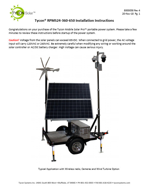
Tycon® RPMS24-360-650 Installation Instructions Congratulations on your purchase of the Tycon Mobile Solar Pro™ portable power system. Please take a few minutes to review these instructions before startup of the power system.Caution! Voltage from the solar panels can exceed 65VDC. When connected to grid power, the AC voltage input will carry 120VAC or 240VAC. Be extremely careful when modifying any wiring or working around the solar controller or AC/DC battery charger. High Voltage can cause serious injury.Typical Application with Wireless radio, Cameras and Wind Turbine OptionNotes:1.The basic trailer systemcomes complete with abattery control box outfittedwith eight 6V 180Ahbatteries, a 40A MPPT solarcontroller with 20A loadoutput, a 900W AC/DCBattery Charger, a 24VDC to56VDC 5A converter, aTPDIN-Monitor-WEB2 remotepower monitor, a 18’pneumatic extension mastwith 12V air-pump, a junctionbox at top of pole with a 5Port Gigabit versatile PoEswitch, and 650W of solarpanels with travel cover.2.When travelling, werecommend to always usethe solar panel cover to helpprotect the solar panels fromflying road debris. Make sureall bolts and nuts are tight.Also, the solar panels need tobe set for 10° position (nearlyhorizontal) and secured withthe included ratchet straps.3.When parked, even forstorage, we recommend toalways extend the 4stabilizers to prevent trailer damage from high winds.4.There are multiple components included in the trailer system. Each component has its ownuser guide; therefore, this user guide will just touch on the system basics.Procedures:1) Trailer Startupa) Park the trailer in such a way that when deployed, the solar panels won’t be shaded by theextension mast during peak sun. This usually means that the front of the trailer will be facing North. Solar panels need to be facing due South in the northern hemisphere.b) There are 4 outrigger stabilizers thatca n be extended 15” or 30”. Extendthese outriggers and use them to levelthe trailer.c) Make sure both red disconnectswitches are set to the OFF position.d) Set solar panels to face South and setthe tilt angle. Tighten all the adjustmentbolts. Optimum Solar panel tilt dependson latitude and time of year. There is ahandy calculator on to help you determine the best tilt anglefor your area.2) Powering up the systema) Note: The solar controller should always be connected to the batteries before being suppliedwith solar power.b) The system ships with two 30A fuses removed from the batterycables. Install both fuses to power up the system. The fusemay spark when inserted. This is normal.c) Turn the red battery disconnect switch to ON, then turn on thered solar disconnect switch to ON. The MPPT solar controllerwill powerup. The MPPT solar controller has a load outputwhich supplies power to the TPDIN-Monitor and the 24VDC to56VDC converter. Press the red SET button on the MPPT solarcontroller to turn the load on and off.d) The TPDIN-Monitor-WEB2 controls the power going to the topof the extension pole through two of the on-board relays. RelayCH1 controls the 56V supply. Relay CH2 controls the 24V supply. By default, these relays are closed. The TPDIN-Monitor-WEB2 allows control of the relays using manual control or based on measured parameters or ping. To find out more about the TPDIN-Monitor-WEB2 features and use, refer to the individual product user guide. The unit ships with DHCP client enabled and fallback IP is 192.168.1.63) Pneumatic Extension Mast - Raisinga) The pneumatic extension mast is raised using a 12V automotive air pump. The 12V for thepump is supplied from the 24V batteries using a 24V to 12V DCDC converter. There is apressure regulator with air valve used to raise or lower the mast. The mast has mechanical locks at 9’,12’,15’ and 18’ positions so the mast can be raised to any of these pre-definedheights. It takes about 1 minute to fully extend the mast using the air pump.b) Near the top of the mast, there is a die cast aluminum enclosurehousing a TP-SW5G-VERSA PoE gigabit switch. The input tothe switch is 56VDC and the outputs are as follows: Port 1 60WHigh PoE(4 pair); Port 2-4 802.3at 30W; Port 5 24V 12WPassive PoE. If it is necessary to connect a laptop orcomputer to the switch, connect to port 2,3 or 4 only.Connecting to port 1 or 5 could cause damage to yourcomputer Ethernet port.c) A wire terminal is included inside the housing to supply 24VDC15A unregulated and 56VDC 5A regulated.d) Turn off the voltage output from the MPPT solar controller by pressing the SET button. Mountequipment and connect the equipment to either the PoE switch or the wire terminal, asrequired. Power up the load by pressing the SET button on the MPPT solar controller. Once the equipment is connected and tested, the mast can be raised.e) Raise the mast by turning the air flow valve to the “UP” position. Turnon the 12V air-pump using the toggle switch. Note: The pressureregulator at the airflow valve should be set to 30PSI.f) You will hear the mechanical locks click into position as the mast israised. You can turn off the 12V air-pump at an intermediate height orafter the mast is fully extended. Once the mast is extended turn theairflow valve to the center position.4) Pneumatic Extension Mast - LoweringNote: If mast has been extended for a long time it may become depressurized and will need to firstbe pressurized using the air pump before attempting to lower it.a) Lowering the mast is a little tricky. Don’t relieve all the pressure then pull themechanical lock rings. This will cause the mast to fall and bang against thelower section. This could damage equipment mounted on the mast.b) To lower the mast slowly:i) Turn the air flow valve to the “DOWN” position. Immediately pull the bottom lock ring. Themast will begin to collapse.ii) When the mast section is about half way down, pull the next lock ring. Repeat till all the lock rings are pulled and the mast has collapsed fully.5) Charging the batteries from AC powera) The batteries can be charged using 115VAC or 230VAC grid power. This is useful if you wantto fully charge the batteries before each deployment.b) CAUTION: Make sure to set the voltage switch on the TP-BC48-900 battery charger to the correct AC voltage. Default is115VAC. Failure to set the correct voltage will damage thebattery charger.c) Connect an extension cord to the weatherproof AC receptacleon the back of the battery/equipment box. Connect theextension cord to the proper 10A AC voltage outlet. The battery charging process will startwithin a few minutes. It should take about 5hrs minimum to fully charge the dischargedbatteries.6) MPPT Solar Controllera) The advanced MPPT solar controller measures solar voltage andcurrent, battery voltage, load current and temperature. You can scrollthrough the various readings on the display by pressing the up anddown arrow keys on the controller. Please refer to the solar controlleruser guide for detailed info.b) There is a Bluetooth interface included so you can check status of thesystem using your smartphone without having to open the equipmentenclosure. The range is about 15’. Please refer to the TP-SC-BT1user guide for more info.7) Misc. Informationa) The enclosure includes a thermostatically controlled fan. The fan will turn on automatically ifthe temperature inside the enclosure exceeds 45C.b) The batteries used in the system are GEL type sealed lead acid batteries. They aremaintenance free and should last at least 5 years. Caution: Never store the batteries in adischarged state, especially in cold temperatures or else the battery life will be reduced.Always store the batteries fully charged.c) A second locking enclosure can be added to the trailer platform in order to store userequipment.d) A wind turbine option is available to add a second source of power to the system. The windturbine mounts to a separate foldable mast system which is included in the optional kit.e) Replacement fuses:i) Battery Cables: ATC/ATO (.75”) Automotive Fuse 30Aii) AC/DC Battery Charger: 6x30mm 25A glass fuseSchematic:。
亚特兰蒂斯·科波克 QAS 25-45 ID T4F 移动电源说明书

Standard Scope ofSuppl yMobile GeneratorThe Atlas Copco QAS 25 & QAS 45 ID T4F generators are prime power, multi-voltage, sound attenuated, mobile generators. They are powered by an Isuzu Tier 4 Final, liquid-cooled, four cylinder diesel engine.The units consist of an alternator, diesel engine, cooling system, electrical distribution and control systems - all enclosed within a sound attenuated enclosure fabricated from powder coated galvanealed steel. A broad range of undercarriage formats and options are available.Special attention has been given to the overall product quality, user friendliness, ease of serviceability, and economical operation to ensure best in class total cost of ownership.Available ModelsQAS 25 ID Multiple voltage – 25kVA prime power – Isuzu engi ne QAS 45 IDMultiple voltage – 45kVA prime power – Isuzu engi neStandard FeaturesB enefits•Compact, sound attenuated, corrosion resistant enclosure with single point lifting and 110% fluid containment•Extremely durable and environmentally sensitive,designed to be used for everything from the oil patch to special event power•Available as a skid mounted unit with forklift pockets, or on a single axle trailer•Versatility, giving you the flexibility to match your machine to the correct application•Heavy Duty alternator with AREP excitation and marine grade protection•Start-up power for the most demanding sites with 300% over load starting capabilities•“DeepSea” controller•Reliable and intuitive controls for ease of use and diagnostic capabilities•Single side servicing with long run filters and 500 hour service intervals•Heavy duty oil, air and fuel filters extend the maintenance interval to 500 hours for reduced total cost of ownership•Reduces maintenance costs with long intervals easy access for mechanics•Extremely reliable and durable Isuzu 4LE engine with EGR &DOC after-treatment and limited 5 year limited warranty •Proven engine platform with high reliability, a simple maintenance free Diesel Oxidization Catalyst only after treatment•Identical enclosures and maintenance points between both models•Reduces stock of service kits and inventory of parts with rental ROI kept in mind•Emergency Stop •External, recessed emergency stop for increased safety •Remote Start / Stop•Allows connection as a critical back-up unit via a 2 wire dry contact connection in the distribution panelTechnical Data 11 All ratings are at a reference condition of 0’ altitude and 20°C (72°F)2 Please see receptacle voltage configuration in Power Distribution section on page #53 Engine oil to meet CJ-4 (low ash oil)4 Please see “Derate Table” for altitude and temperature calculations on page #45 Cold start option comes with 120V block heater and 0W40 synthetic engine oil6 Measured in accordance with ISO 2151 under free field conditions @ 7m distance7 Engine and emissions require the use of Ultra Low Sulfur Diesel in accordance to ASTM-D975 Grade No.1-D S15 & No.2-D S15 8 Based on 90% volume of fuel tankGeneratorUnitsQAS 25 IDQAS 45 IDRated Prime Power 3Ø kW / kVA 20/25 36/45 Rated Standby Power 3Ø kW / kVA22/2840/503Ø Power Factor0.8 3Ø Voltage In 480V Switch Position (Series Star w/ Neutral) V 480Y/277Amp Capacity @ 480VA 30543Ø Voltage In 240-208V Switch Position (Parallel Star w/ Neutral)V 240YY/139-208YY Amp Capacity @ 240V A 60 108 Amp Capacity @ 208V A 60 125 Rated Prime Power 1Ø kW / kVA 16/1627/27 1Ø Power Factor1.0 1Ø Voltage In 120-240V Switch Position (Zig-Zag) V 240/120Amp Capacity @ 240V A 67 90Amp Capacity @ 120V A67 x 2 90 x 2 Alternator (4 Pole, 12 Wire) Leroy Somer LSA 40 M5LSA 42.3 S5ExcitationAREP Automatic Voltage Regulator (+/- 0.5%) Leroy SomerR438 Insulation Class HFrequencyHz 60 60 Main Breaker - Shunt TripA63 125 Power Distribution – Terminal Board 5 Wire (L1, L2, L3, N, Ground)Terminal Board Connections Bare Wire TerminalsMaximum Terminal Cable Size 350MCMConvenience Receptacles 22 x NEMA 5-20R & 2 x 125/250V 50ACS6364EngineUnitsQAS 25 ID QAS 45 IDModelIsuzu4LE2T 4LE2X US EPA Family ESZXL02.2ZTB ESZXL02.2PXBUS EPA Tier Tier 4 FinalDisplacement L 2.18 Cylinders# 4Continuous Engine Power Output HP (kW) 31.5 (23.5) 59 (44) Gross Engine Power Output HP (kW) 40 (30) 66 (49)Rated Speed RPM1800 Engine Control ECUAspirationTurbocharged Turbo w/ IntercoolerEngine oil capacity 3US Gal (L) 1.9 (7.2)Engine coolant capacityUS Gal (L) 3 (11.4) 2.11 (8)Maximum Ambient Temperature (@ Sea Level)4°F (°C) 122 (50)Minimum Starting T emperature (Without cold weather options)°F (°C) 14 (-10) 14 (-10) Minimum Starting T emperature (With cold weather kit)5°F (°C) TBA TBA Electrical System (Negative Ground) V 12 12 Engine Alternator OutputA 50 50 Battery Capacity (Cold Cranking Amps) A 650 650 Sound Pressure Level @ 23’(7 m) @ 75% Load 6dB(A)6766Fuel SystemUnitsQAS 25 IDQAS 45 IDFuel Consumption @ 25% load US Gal/hr (L/hr) 0.7 (2.6) 1.2 (4.6) Fuel Consumption @ 50% load US Gal/hr (L/hr) 1.0 (3.8) 1.8 (6.9) Fuel Consumption @ 75% load US Gal/hr (L/hr) 1.4 (5.3) 2.15 (8.1) Fuel Consumption @ 100% load US Gal/hr (L/hr) 1.6 (6.1)2.76 (10.4)Fuel TypeUltra Low Sulfur Diesel ONLY 7Fuel Tank CapacityUS Gal (L)73 (274)Fuel Autonomy @ 75% load 8Hr46.630QAS 25-45 ID T4F – Product ReferenceDime nsi on sTrailer MountedSkid MountedWeight - Wet (ready to operate)UnitsQAS25 IDQAS45 IDTrailer Mountedlbs (Kg) 2,396 (1,086)2,625 (1,191Skid Mountedlbs (Kg)2,290 (1,040)2,440 (1,109)DimensionsTrailer Mounted (L x W x H) Inches Skid Mounted (L x W x H)Inches129.5 x 54 x 66 75 x 34 x 55QAS 25-45 ID T4F – Product Reference Principle DataAlternatorThe Leroy Somer LSA alternators are designed for heavy duty continuous applications, with marine winding protection and Leroy Somer’s AREP excitation system.•AREP Excitation for superior motor starting capabilities•Marine grade (relative humidity >95%) protection•External multi-voltage selector switch (3 – position)• 4 pole brushless design with single bearing, Class H insulation and IP23 rating•Voltage regulation +/- 0.5%•Full Load acceptance of prime power ratingThe AREP system uses 2 independent auxiliary windings located in the main stator to send supply voltage to the AVR: •The voltage delivered by the first auxiliary winding H1 is proportional to the alternator output voltage (shunt characteristic).•The voltage delivered by the second auxiliary winding H3 is proportional to the current drawn by the alternator and is a function of the applied load (compound characteristic – booster effect).•The resulting phase-to-phase voltage supplies power to the AVR.This power supply to the AVR power circuit is independent of the voltage sensing measured on the alternator output terminals. Therefore, the excitation current delivered by the AVR to the alternator exciter is independent of any voltage distortions (harmonics) due to the load.The AREP system gives the alternator a high overload capacity (load impact or starting electric motors) and a short-circuit capability (300% -10 s) in order to provide discriminating protection: the alternator with AREP excitation is shorter than the one with PMG excitation. It is particularly suitable for demanding applications.Performance @ Altitude and High Ambient ConditionsWhen using at altitude and high ambient conditions the engine and alternator will de-rate as per chart below.Temperature °C (°F)Height m (Feet)0 (32) 5 (41) 10 (50) 15 (59) 20 (68) 25 (77) 30 (86) 35 (95) 40 (104) 45 (113) 50 (122)0 100% 100% 100% 100% 100% 100% 100% 100% 100% 100% 100%500 (1640) 100% 100% 100% 100% 100% 100% 100% 100% 100% 97% 94% 1000 (3280) 100% 100% 100% 100% 100% 100% 100% 100% 100% 97% 94% 1500 (4921) 100% 100% 100% 100% 100% 100% 100% 99% 97% 94% 91% 2000 (6561) 100% 100% 100% 100% 100% 98% 97% 95% 94% 91% 88% 2500 (8202) 100% 100% 100% 100% 100% 95% 94% 92% 91% 88% 86% 3000 (9842) 100% 100% 100% 100% 100% 91% 90% 88% 87% 84% 82% 3500 (11,482) 100% 100% 100% 100% 94% 88% 84% 81% 80% 78% 77% 4000 (13,123) 75% 75% 75% 75% 75% 75% 75% 75% 75% 75% 75%QAS 25-45 ID T4F – Product Reference Power DistributionThe main power is connected from the alternator through a 3 position voltage selector switch to the main power cubicle. The cubicle incorporates all power distribution, controls, sensing and protection devises.✓ 3 position Voltage Selector Switch (VSS)✓Current transformer x 3 (1 each leg)✓Single main breaker w/shunt trip✓Individual breakers for each receptacle✓Convenience receptacles located on outside of unit for easy access✓Terminal board for hard wiring✓Cam-Lock external quick connect (available as option)✓External emergency stop switch (recessed)✓Neutral bonded to Ground with a removable bonding link accessible in the control cubiclePlease refer to the chart below for power distribution and voltages. NOTE: All voltages below are subject to change, depending on set point of “Fine Voltage Adjustment” potentiometer and Voltage Selector Switch.•All voltages are adjustable with the “Fine Voltage Adjustment” potentiometer located on the control panel. Therefore voltage may be different then what is shown in the above table. All voltages should be verified before connection to the unit.QAS 25-45 ID T4F – Product Reference ControllerThe QAS25 and QAS45 comes equipped with a DeepSea 4510 control module. This is a fully diagnostic ECU controller with large 3” display, that is intuitive and easy to operate with all functions conveniently at your fingertips. The controller also manages the engine ECU operating system, and a number of safety warnings and shut downs on various parameters (listed below).The controller is powered by a main On/Off switch located next to unit.DeepSea 4510 Controller Functionality:•Home Page (displayed while running, scrolling every 3seconds)✓Generator voltage (ph-ph)•Operational Buttons✓Start button✓Stop button✓Automatic mode (external remote start)✓Up/Down arrows•Generator Page✓Generator voltage (ph-N)✓Generator voltage (ph-ph)✓Generator frequency •Info Page✓Model number✓USB identification number✓Configured engine type✓Module’s date and time✓Scheduler setting•Load Page✓Generator current (A)✓Load ph-N (kW)✓Total load (kW)✓Load ph-N (kVA)✓Total Load (kVA)✓Load ph-N (kVAr)✓Total Load (kVAr)✓Power factor ph-N✓Power factor average✓Accumulated load (kWh, kVAh, kVArh)•Engine Page✓Engine speed✓Oil pressure✓Coolant temperature✓Fuel level✓Engine battery voltage✓Engine run time✓Engine Maintenance due – Oil (if configured)✓Engine Maintenance due – Air (if configured)✓Engine Maintenance due – Fuel (if configured)•Event Page✓Displays the last 15 events •Engine DTC Page✓This page contains any active Diagnostic Trouble Codes that the engine ECU is currently generating.These alarms are conditions detected by theengine ECU and displayed on the DSE controller.•Remote Start/Stop✓Automatic start stop via 2 wire dry contactconnectionQAS 25-45 ID T4F – Product Reference EngineIsuzu 4LE2Isuzu 4LE2 Tier 4 Final, turbo charged, intercooled (QAS 45 only), four-cylinder, liquid-cooled diesel engine provides amplepower to operate the generator continuously at full-load.Meets all US EPA, CARB and Environment Canada exhaust legislations with Tier 4 Final compliance. The engine utilizes a Diesel Oxidation Catalyst (DOC) to meet Tier 4 Final emissions. All functionality of the engine is controlled automatically on the DeepSea 4510 controller.The engine has the capability to start the generator at 14°F (-10°C) with standard glow-plug aid.The 73 Gal (274L) fuel tank is sufficiently sized to operate the unit at full-load cond itio n for long run times (see chart on page 2 forspecifications).The engine operates on a 12V negative ground electrical system with a 35A charging alternator.The cooling system is suitably designed for continuous operation in ambient conditions up to 122°F (50°C), with canopy door closed.Fuel SystemA large 73 US Gal (274L) steel fuel tank provides safe diesel storage while eliminating tank corrosion contaminants frombeing introduced to your fuel system. With integrated fuel water separator and filter, the system is designed to helpmaintain clean and trouble free diesel supply to the engine for reliable trouble free operation.✓Pad-lockable diesel fill cap✓Fuel / Water separator✓Inline priming pump (w/ filter)✓Fuel pre-filter✓Fuel supply pump (w/ strainer)✓Fuel level sensor✓Low fuel shut down feature (programmable level)Scheduled maintenanceStandard equipped with filters sized and designed to allow 500 hour service intervals under normal operating conditions.Extended time between services reduces down time and total cost of ownership of the unit over its lifetime.•500 Hour Service Interval:✓Air filter✓Oil filter✓Fuel filter✓Fuel / water separator •1000 Hour Service Interval:✓Air filter✓Oil filter✓Fuel filter✓Fuel / water separator✓V-BeltNOTE: Site specific operating conditions such as; poor fuel quality and low load profile may require more frequent service intervals.Enclosure & FrameThe generator enclosure is designed for extreme applications to provide superior performance and reliability.The enclosure is fabricated from galvaneal coated polyethylene which is powder coated for corrosion resistance. The enclosure and frame are fully sealed from the radiator to the back of the unit, providing a true 110% containment of all fluids.✓Galvanealed, powder coated enclosure✓Heavy duty base frame✓110% fluid containment✓Larger 73 gallon, polyethylene fuel tank✓Convenient 2” NPT drain at rear of machine to clean out the containment frame✓Superior level of rain ingress protection and design features✓Pad-lockable doors and fuel cap✓Engine fluid plumbed to exterior of frame for ease of service✓Central lifting point✓Sound dampening material and design to allow quiet operation at 67 & 66 dB(A) respectivelyQAS 25-45 ID T4F – Product ReferenceUndercarriageThe QAS 25 and QAS 45 are available with two undercarriage alternatives, providing utmost flexibility in installation, site handling or towing. Both the skid frame and the trailer mount the same way and can be interchanged for versatility.•Trailer:✓Single axle✓Available with hydraulic or electric brakes (optional no brakes available for the QAS 25 only)✓DOT/Federal MVSS 49CFR571 approved light package and 7 flat blade RV style plug✓Adjustable height pintle hitch (3” lunette)✓15” Rims w/ ST205/75D15 Tires for trailer use✓Heavy Duty torsion axle rated at 3,500lbs w/ brakes 3,000 w/o brakes✓Safety chains✓Screw jack leveling, with pad foot, 3,000 lbs static capacity✓Single point lifting structure✓D-Ring Tie down points x4•Skid mounted:✓Sub-frame skid with integrated forklift pockets✓Heavy duty design for use in extreme conditions✓Frame is ¼” wider then machine to reduce damage from forklifts✓Built-in locations for straps or chains to secure the unit for transport✓Single point lifting structureFactory Options Available•Single axle trailer with hydraulic•2” or 2 5/16” ball hitches (shipped loose)•Trailer stabilizer jacks•Trailer mounted tool box•Cold start kit (120V block heater, 0W40 synthetic engine oil)•Battery charger (12V, 6A)•Battery isolation switch (lockable)•Heavy duty battery (800CCA Optima, Spiralcell AGM, Redtop)•Inlet shutdown valve•CSA approval•External fuel quick connects (3 way valve, located inside of enclosure for spill containment and protection)•Cam-Lok quick connections (5 x 400A)•LoJack® (Stolen Vehicle Recovery System)•Telematics system (DSE Webnet System)QAS 25-45 ID T4F – Product Reference Manufacturing & Environmental Standard sThe QAS 25 & QAS 45 ID T4F are manufactured following stringent ISO 9001 regulations, and by afully implemented Environmental Management System fulfilling ISO 14001 require m ents.Attention has been given to ensure minimum negative impact to the environ ment.The QAS 25 & QAS 45 ID T4F meets all current USSupplied Docu men t ationThe unit is delivered with documentation regarding:•Hard copies of the Atlas Copco Operators Safety and Instruction Manual, Atlas Copco Parts Book, Isuzu Engine Manual and Parts book, in English as well as electronic copies available on request.•Warranty Registration card for engine and Atlas Copco Generators (Units must be registered upon receipt).Warranty Co verag eAtlas Copco Generator: Warrantied to be free from defects with regard to material and workmanship for the period of eighteen (18) months from date of shipment from the factory, or twelve (12) months from date of initial startup, whichever occurs first, without limitation of running hours.Isuzu Engine: Warranty from Isuzu Motors America Inc. Unit must be registered directly with Isuzu Motors America upon receipt to be eligible for warranty. Failure to register warranty upon initial startup may cause warranty claim delays or rejection of claim by Isuzu.•One (1) years / unlimited hours or up to three (3) years / 3,000 hours of operation (whichever occurs first) *•Two (2) years / 2,000 hours of operation (whichever occurs first) on all electrical, fuel system, and turbocharger components**•Major Component Limited Warranty (MCW) for five (5) years / 5,000 hours (whichever occurs first) ****Whichever occurs first. In the absence of a functional hour meter, the engine will be deemed to be in use for eight (8) hours per calendar day commencing from the start of the warranty period.** Coverage for all electrical and/or electronic (including factory-installed wiring harnesses), fuel system, and turbocharger components are limited to two (2) years or 2000 hours, whichever occurs first.*** Major Component Limited Warranty (MCW) covers the following components only: cylinder block, cylinder head, crankshaft (excluding bearings), camshaft,connecting rods (excluding bushings), flywheel and flywheel housing.Leroy Somer Alternator: Warrantied to be free from defects with regard to material and workmanship for the period of twenty seven (27) months from date of shipment from the factory, or twenty four (24) months from date of initial startup or 10,000 hours, whichever occurs first.Extended Warranty Programs: Programs are available; please contact your local sales representative for more info.。
亚特兰蒂斯(Atlas Copco)的可移动电源设备说明书

21kW 2kW 3kW 4kW 5kW 6kW 7kW 8kW 9kW 10kW 11kW IP GENERATORS QEP - QEP R - QEP SP STANDARDPower on the moveAtlas Copco´s portable generators have been made for people who work hard all day, every day! Built to last, every generator in this range delivers long-term reliability, even in the toughest working conditions. Easy operation, built-in safety features and an exceptional build quality make these generators the perfect working partner for construction professionals, no matter the job site or task in-hand. From simple one-person jobs, all the way to large construction sites, we have the solution for you./portable-generatorWhich model is right for you?We offer a full line of portable generators, with the objective of covering all your needs:For general everyday use, or for frequent single job use, the iP and P generators are the perfect solution.If you need something for more intensive use, with higher power levels and extended features then the QEP is the solution for you. All models offer proven reliability, fuel efficiency, low noise levels and longrun times between refueling – with a combination that is right for every application.The iP and P generators are focused on contractors for personal use, who require portable power at a moment’s notice. The QEP is perfect for rental use or larger work sites where the power needs to be shared. The extended safety features of the QEP R minimize the risk of damage to the generator through misuse. Other safety features include an onboard differential circuit breaker. When it comes to urban environments and even lower noise levels, then the QEP S, with its noise suppression design, providesthe perfect companion./portable-generator34iP generators offer a compact, fuel efficient, plug and play power solutionAll in one/portable-generator/portable-generator5When it comes to fuel efficiency, compactness and noise attenuation, iP generators are the future. The variable speed smart control, together with paralleling capability, delivers efficient power with the lowest fuel consumption, adapting engine speed to the load conditions.iP portable generatorsTime tested performanceThe P range of generators provide: long runtimes, durability, voltage regulation and reliable performance/portable-generator7P range generatorsThe P range offers high performance, robust design and simple maintenance. This range is ideal for construction, livestock farming, and agriculture, to name just a few industries. These products have been designed at our innovation center to guarantee the highest quality standards.(**) Dimensions without wheels mounted8The QEP range of portable generators. Designed to work hard all day, every day Built to last/portable-generator/portable-generator 9Built to last, every QEP generator delivers long-term reliability under the toughest working conditions. Easy handling, safety and exceptional build quality make QEP generators the perfect working partner for construction professionals.QEP WQEP DIESEL**Only available at 50HzTechnical dataKey features / Standard• Recoil start • Sockets• Recoil start • Fuel valve• Wheel kit• Welding kit including cables and mask• Wheel kit• Differential circuit breaker, hour meter **Key features / OptionsQEP PETROL • Recoil start • Large fuel tank• Fuel valve • Wheel kit• AVR, differential circuitbreaker and hour meterQEP generators• Sockets• Engine oil guard(Protection shutdown on low oil level)• Thermal protection • CE noise compliance • Protective top cover• CE noise compliance• Engine Oil Guard(Protection shutdown on low oil level)• Selector 8 positions for welding current• Sockets• Thermal protection/portable-generator10QEP R generators/portable-generator11Technical dataQEP S generatorsAtlas Copco Power Technique /ptbaProduct portfolio*Multiple configurations available to produce power for any size applicationONLINE SOLUTIONSPORTABLE 1,6–12 kVAMOBILELARGE POWER 9–1250* kVA 800–1450 kVAINDUSTRIAL 10–2250* kVAGENERATORSSHOP ONLINE PARTS ONLINEPOWER CONNECT Find and order the spare parts for power equipment. We handle your orders 24 hours a day.Scan the QR code on your machine, and go to the QR Connect Portal to find all the information about your machine.ENERGY STORAGE SYSTEMZENERGIZEDIESELBATTERYELECTRICLIGHT TOWERSAIR COMPRESSORS AND HANDHELD TOOLSAIR COMPRESSORS HANDHELD TOOLS FLEETLINKIntelligent telematicssystem that helps optimize fleet usage and reduce maintenance, ultimately saving time and cutting operating costs.1–116 m³/min 7–345 barPneumatic HydraulicPetrol engine drivenDiesel and electric options availableDEWATERING PUMPSELECTRIC SUBMERSIBLE 250–16.200 l/min833–23.300 l/minSURFACE PUMPS LIGHT THE POWER YOUR SIZING TOOL A useful calculator to help you choose the best solution for your power and light needs2958 1010 02 - v 04- © A t l a s C o p c o P o w e r a n d F l o w d i v i s i o n . 2020。
阳光电源调eward逆变器SG225HX用户手册说明书

4.4.2 起吊搬运 ........................................................................................... 22 4.5 安装挂板..................................................................................................... 23
1 安全说明 ........................................................................................................... 1
1.1 拆包检查....................................................................................................... 1 1.2 安装安全....................................................................................................... 2 1.3 电气连接安全 ................................................................................................ 2 1.4 运行安全....................................................................................................... 3 1.5 维护安全....................................................................................................... 4 1.6 报废安全....................................................................................................... 4
- 1、下载文档前请自行甄别文档内容的完整性,平台不提供额外的编辑、内容补充、找答案等附加服务。
- 2、"仅部分预览"的文档,不可在线预览部分如存在完整性等问题,可反馈申请退款(可完整预览的文档不适用该条件!)。
- 3、如文档侵犯您的权益,请联系客服反馈,我们会尽快为您处理(人工客服工作时间:9:00-18:30)。
迪比科移动阳光S1太阳能移动电源
现如今,移动电源无论是外观形态还是内在功能上都已经发生了翻天覆地的变化。
看似一个小小的移动电源,其本身的功能是非常丰富的。
比如有的移动电源集成了路由器功能、云存储功能甚至是音箱功能……然而,移动电源的本质就是为了解决数码产品没电的烦恼,其本身也是数码产品,也需要充电,外出时我们也经常遇到移动电源忘充或是移动电源没电的尴尬。
不过,这一尴尬有望被化解,迪比科就推出了一款型号为移动阳光S1的太阳能移动电源,号称有光
的地方就能充电。
外在:单晶硅太阳能面板+双USB输出
从打开包装盒看到移动阳光S1的第一眼,最引入注意
的还是它所采用的太阳能面板。
S1的正面覆盖的是一块长11.5cm,宽6cm的单晶硅太阳能面板。
S1的外壳采用了塑料材质,整体以黑色为主,中间加入了一圈黄色。
S1背部则是其铭牌信息,可以看到它的相关参数。
在接口方面,S1搭配了两个USB输出接口,支持1A和2.1A输出。
在USB输出接口中间还搭配有一个LED灯。
在S1的侧面则是输入接口,
最大支持5V/2A输入。
输出:1A/2.1A输出电压曲线平稳
移动阳光S1标称拥有37Wh(10000mAh×3.7V)电能,我们分别对其进行了1A和2.1A下放电测试。
在1A的设置下,我们将迪比科移动阳光S1通过电子负载仪进行了测试。
连接S1后,可以看到其待机电压为5.05V,在1A下的整体
放电曲线很平稳,没有明显的波动。
S1的初始放电电压在4.69V左右,截止电压为4.7V,平均电压为4.7V,整体放电
电压非常平稳。
在1A下,S1一共放出32.81Wh(6981mAh
×4.7V)电能。
而在2.1A下,S1的初始放电电压在4.51V,截止电压为4.48V,平均电压为4.49V。
可以看到在2.1A的
电压虽然下降比较明显,但是整体的放电电压还算比较稳定,放电曲线也很平稳。
最后,S1在经过近三个小时的放电后,共放出27.37Wh(6097mAh×4.49V)电能。
体验:S1需要强光才能进行太阳能充电
迪比科移动阳光S1采用的是单晶硅太阳能面板,目前
市场上除了该太阳能面板外,还有多晶硅太阳能电池板和非晶硅太阳能电池板(薄膜太阳能电池板)。
单晶硅太阳能面
板也是目前市场上应用相对比较广泛的一种面板,其光电转换效率通常在15%左右。
换而言之就是说每平方米太阳能面板吸收1000W的能量,理论上转化出来的电能是150W左右。
而S1的这块太阳能面板面积约为0.0069m2,相当于可以转
化出1W左右的电能。
在实际使用中,S1需要在光线非常充足的太阳光的照射下才能充电,如果是阴天或是光线一般的
室内无法充电。
同时,迪比科移动阳光S1在通过太阳能充电时的充电速度也很慢,官方标称为5V/200mA,相当于只有普通5V/1A的五分之一。
此外,我们对S1进行了在太阳能下的充电测试,由于天气的原因,我们通过台灯直接照射在S1太阳能面板上进行模拟太阳能充电。
在经过近20个小时的不间断照射后,我们看到其大约充进了20%左右的电量,可以想象,如果在实际使用中单纯依赖太阳能充电,其速度之慢!实用性打了折扣。
拆解:聚合物电芯+ACT2802主控
对于这款S1太阳能移动电源,我们也非常好奇其内部到底是怎样的,我们对其进行了拆解。
拆开后,可以看到S1采用的是两块5000mAh组成的10000mAh聚合物电芯。
S1采用的电芯编号为SP5666113,经查询该电芯为迪比科自己生产。
在PCB端,我们看到其采用了一颗型号为28020L的技领半导体公司(Active-Semi)生产的主控IC。
通过官方的PDF资料显示,这是一颗最高拥有5V/2.5A输出的IC,可适应4.1V到4.35V的电池电压,并具备过流、过压、过温、短路等保护功能。
此外,在PCB的另一面,搭配有一颗编号为:N79E814AT20新唐生产的单片机,其主要负责电量的显示。
同时,拆开后的太阳能面板也呈现在我们的面前。
该太阳能面板是由迪比科旗下的子公司广州奥鹏生产,其结构并不复杂,两根连接线将太阳能板和PCB端连接即可。
下面,我们
来看看电芯的放电情况如何。
电芯:实测电芯容量超出标称值
我们对移动阳光S1的电芯进行了测试,通过分容器的测试后,其容量为39.25Wh(10609mAh×3.7V),实际电芯容量已经超出了标称值。
而由此我们也能计算出S1在1A和2.1A的转换效率分别为:84%和70%,就转换效率来看,迪比科移动阳光S1不能说是优秀产品,只能算是一款合格产品。
写在最后
作为一款支持太阳能充电的移动电源,迪比科移动阳光S1可以说是一款具有创新性的产品。
虽然搭配的太阳能充电效率不高,但也不可否认这是移动电源创新的进步。
而从整体的性能来看,移动阳光S1的放电电压稳定,没有波动。
转换效率方面虽然不是很高,但还是达到了合格水平。
此外,售价仅―百元出头的价格,也算实惠,特别是在搭配了太阳能面板后,相对于普通的―万毫安时移动电源价格来说很有竞争力,整体来说是值得购买的。