Advanced Voltage Positive Feedback Control for Anti-islanding
增强并网逆变器对弱电网适应能力的控制策略

文献[4]提到了一种对前馈通道的选频处理 办法,可以有效减少电网阻抗在谐振频率段的幅 值,增强并网逆变器对弱电网的适应能力。文献 [5]提出了一种基于电压型阻抗适配器的控制策 略,通过虚拟较小的谐波阻抗,对公共耦合点进 行阻抗重塑,继而降低谐波。文献[6]基于同步频 率谐振现象的产生原理,提出基于暂态虚拟电阻 的阻尼控制策略来解决谐振问题,但其关于弱电 网条件下电压前馈控制对并网逆变器的影响机
ELECTRIC DRIVE 2021 Vol.51 No.9
电气传动 2021 年 第 51 卷 第 9 期
增强并网逆变器对弱电网适应能力的控制策略
张硕文,苗虹,曾成碧 (四川大学 电气工程学院,四川 成都 610065)
摘要:弱电网中,并网逆变器与感性电网阻抗之间产生交互耦合从而引发谐振现象,采用电压比例前馈控 制虽然可以抑制谐振,但其额外引入的正反馈回路也会降低并网逆变器的相角裕度。针对这种局限性,建立 LCL 逆变器并联系统的数学模型及诺顿等效电路,再利用阻抗法分析电压前馈控制对系统稳定性的影响,并 提出了一种新型的基于相位超前补偿的电压前馈控制策略,既保留了传统电压前馈控制的优点,又增大了并 网逆变器输出阻抗的相角裕度,使系统对电网阻抗具有较强的鲁棒性。最后,通过仿真验证了新型控制策略 的可行性。
(School of Electrical Engineering,Sichuan University,Chengdu 610065,Sichuan,China)
Abstract: In a weak grid,the resonance phenomenon is caused by the interaction coupling between the gridconnected inverter and the inductive grid impedance. Although voltage proportional feedforward control can be used to suppress resonance,the additional positive feedback loop introduced will also reduce the phase angle margin of the grid-connected inverter. For these problems,a mathematical model and Norton equivalent circuit of LCL inverter parallel system were established,and the influence of voltage feedforward control on the stability margin of the system was analyzed by impedance method. Aiming at the limitations of traditional voltage feedforward control,a new voltage feedforward control strategy based on advanced phase compensation was proposed,which not only retains the advantages of voltage feedforward control,but also increases the phase angle margin of the output impedance of the grid-connected inverter,and improves the adaptability of grid-connected inverters to weak grids. Finally,the feasibility of the new control strategy was verified by simulation.
AMS3132

General DescriptionThe AMS3132 is a high performance linear regulator with very low dropout voltage and excellent transient response. It is designed to operate with wide input voltage range of 1.5 – 7Volts making it ideal for two step conversion while maintaining high efficiency for many power sensitive applications. The device is capable of supplying 3A of output current with a typical dropout voltage of 700mV at 3A. The product is available in either fixed or adjustable output voltage.The linear regulator has been optimized for noise sensitive applications. The device includes an optional enable pin for electrical on/off of the regulator. Forcing the enable pin to logic low shuts down the LDO and reduces the supply current to less than 1µA.The product includes complete short-circuit and thermal protection. The combination of these two internal protection circuits gives the device a comprehensive safety system to safe guard against extreme adverse operating conditions.The AMS3132 is available in a 5-pin surface mount TO263 package, and it is rated for -40°C to +125°C temperature range.Features•V IN range: 1.5 – 7V•Fixed and Adjustable output voltage as low as 0.6V•3A maximum output current•700mV typical dropout voltage at 3A• Low self noise•Optional Power Good (PG) output•Optional Enable (EN) pin for LDO on/off•125µA typical supply current•PSRR >40dB at 10KHz•Stable with Electrolytic, Tantalum orCeramic capacitors•Current Limit protection• Over-Temperature Shutdown•-40 to +125°C temperature range•Available in a 5-pin surface mount TO-263 package•RoHS & WEEE compliantApplications• Set-top Box•DVD, Blue-ray DVD writers•LCD TVs and LCD monitors•Battery Powered Equipment• Infotainment•Wireless & RF Applications•High Efficiency “Green” Laptops & notebookTypical ApplicationPin Description (TO-263 5-Pin Package)Pin #Symbol Description1ENEnable pin. It controls the electrical on/off of the device. When connected to logic low, the device shuts off and consumes less than 1µA of current. Logic high willresume normal operation.PGPower Good pin. It is an open collector, active high output that indicates thestatus of the output voltage. When output voltage (V OUT) exceeds the PG trip threshold, the PG pin goes in to a high impedance state. When the device is out of regulation or shutdown, the PG pin is pulled low. A 10KΩto 1MΩresistorshould be connected from PG to VOUT.2 VINInput supply Voltage. It powers the internal control circuitry and the internal power switch. Bypass V IN with at ceramic capacitor from this pin to ground.3 GND Groundconnection. 4V OUT OutputVoltage5ADJProvides feedback to error amplifier from the resistive divider that sets the outputvoltage.PGPower Good pin. It is an open collector, active high output that indicates thestatus of the output voltage. When output voltage (V OUT ) exceeds the PG trip threshold, the PG pin goes in to a high impedance state. When the device is out of regulation or shutdown, the PG pin is pulled low. A 10K Ω to 1M Ω resistor should be connected from PG to V OUT .Pin ConfigurationAbsolute Maximum Ratings (1)Maximum Input Supply Voltage (V IN )………......…. ……-0.3V to 15V Enable Voltage (EN)…………..…..……………….……...-0.3V to 15V Power Good (PG).……………..…..……….……………...-0.3V to 15V Adjustable Voltage (ADJ)……………………….………… -0.3V to 3V Storage Temperature Range……………...................-65⁰C to 150⁰C Lead Temperature…………………..………….………..……… 260⁰C Junction Temperature………...………………..…………..…… 125⁰CRecommended Operating Conditions (2)Input Voltage…………………………………….………….. 1.5V to 7V Ambient Operating Temperature………….………… -40⁰C to 125⁰CThermal InformationTO263-5 θJA (3)…………………………....…………...….…...30⁰C/WElectrical CharacteristicsUnless otherwise noted: V IN =3.3V; V OUT =1.8V; C IN =10 µF ; C OUT =22µF; -40⁰C ≤T A =T J ≤85⁰C; T J(Max.)= 125°C; Typical values are T A =25°CParameterSymbolConditionsMin. Typ. Max.UnitsOutput Voltage Accuracy VOUT-3 3 %Adjustable VoltageV ADJ Adjustable V OUT only 0.588 0.6 0.612 V Adjustable pin bias current I ADJ_Bias Adjustable V OUT only 10 100 nA Maximum Output Current I OUT_Max3 A Load Regulation I OUT = 0 – 3A 0.1 %Line Regulation V IN =3.0 – 7.0V; I OUT =100mA0.1 % Supply Current I SUP V IN =3.3V, Io=0A0.6 1 mA Shutdown Current I SHDN V IN =3.3V, V EN =0V <1 3 µACurrent LimitI LIM6 ADropout VoltageV DOI OUT =0.1A; V OUT =95% of V OUT(NOM) 60mVI OUT =1A; V OUT =95% of V OUT(NOM) 220I OUT =2A; V OUT =95% of V OUT(NOM) 420 I OUT =3A; V OUT =95% of V OUT(NOM)700PSRRΔV OUT /ΔV INF =10KHz Io =20mA 40 dB Output Noise Voltage e n BW= 100Hz –100 KHz C OUT = 22µF I OUT = 2.75A125 µV(rms) Enable Threshold LowV EN(L) Optional EN Pin present 1.2 V Enable Threshold High V EN(H) Optional EN Pin present 1.3 V Input Enable Low Current I EN(L) V EN = 0V 0 10 nA Input Enable High Current I EN(H) V EN = 1.5V150 300 nA Power Good Low Threshold V PG % of V OUT PG ON / Opt. PG pin only 89 % Power Good High Threshold V PG % of V OUT PG OFF / Opt. PG pin only97%Power Good Output Low Voltage V PGLIPG_SINK = 500μA, Fault Condition200 300 mV Power Good Leakage Current I PG PG off, V PG = 12V 0.01 μA Thermal ShutdownT SD 145 °C Thermal Shutdown HysteresisT SD_HYS15 °CNotes:1. Stresses above those listed in Absolute Maximum Ratings may cause permanent damage to the device.2. Junction to ambient thermal resistance with the TO-263 package tab soldered to a double side printed circuit board with 2.5 in 2 of (1 oz.) copper area.3.With package soldering to 0.5in 2 copper area over backside ground plane or internal power plane θJA can vary from 20°C/W to >40°C/W depending on mounting technique . The thermal resistance Junction to Case is 45⁰C/W. Total power dissipation for the switching regulator and the LDO should be taken in consideration when calculating the output current capability of each regulator.TyO u t u t V o l t a g e (V )O u t u t V o l t a g e E r r o r (%)u t p u t V o ypical Perfo 1.7921.7941.7961.7981.8001.8021.804-50p Ou 3p -0.3-0.2-0.10.00.10.20.30.0Ol t a g e C h a n g e (%)ormance C -250Ambient T utput Voltage(Fixed Volta 4Input l 0.1Output Load Characteris 255075Temperature e Temperatur ge Option) V 5Voltage (V)lation V OUT=1.0t Current (A)d Regulation stics (T A = 25100125e (ºC)re Variation V O = 1.8V67V10.n 25°C unless o5.0A d j u s t a b l e V o l t a g e (V )V o l t a g e (V )V o l t a g e (V )otherwise sp 0.5970.5980.5990.6000.6010.6020.603-50-2Ad Vari 0.00.20.40.60.81.0-50-2Dro 0.00.10.20.30.40.50.60.70Drop pecified)25025Ambient Te djust (ADJ) V ation (Adjus 25025Ambient Te opout Voltag 0.51Output pout Voltage 55075emperature (Voltage Temp stable Voltag 55075emperature (ge vs. Tempe 2A1 A3A1.52Current (A)e vs. Output V100125(ºC)perature e Option)100125°C)erature2.53Current OTypical Performance Characteristics (T A = 25°C unless otherwise specified)0.00.51.01.52.001234567S h u t d o w n C u r r e n t (µA )Input Voltage (V)Shutdown Current vs. Input Voltage125°C‐50°C25°C0102030405060700.00.5 1.0 1.5 2.0 2.5 3.0G r o u n d C u r r e n t (m A )Output Current (A)I GND vs. Output Current V O =2.5V, V IN =3.3V100 µsec/divEnable Start-Up2.5A, V OUT =2.5V,V IN =3.3V, C IN =C OUT =22µFEnable 1V/divV OUT 1V /div10 µsec/divLoad Transient200mA to 2.8A, V OUT =2.5V,V IN =3.6V, C IN =C OUT =22µFI SW OUT1A /divV OUT 50mVac/divFunctional Block DiagramFigure 1: Block Diagram of AMS3132 5-Pin TO-263 Fixed Voltage with Power Good OptionFigure 2: Block Diagram of AMS3132 5-Pin TO-263 Adjustable Voltage OptionFunctional Block DiagramFigure 3: Block Diagram of AMS3132 5-Pin TO-263 Adjustable Voltage with Power Good OptionDevice SummaryThe AMS3132 is a high voltage low drop out linear regulator with a current capability of up to 3A. The LDO has a recommended operating input voltage range of 1.5V to 7V with an output voltage as low as 0.6V and is stable with a wide range of ceramic, tantalum, and electrolytic output capacitors. Shutdown/EnableThe Enable (on/off) input threshold voltage is 1.2V. When disabled the LDO quiescent current decreases to a typical value of <1µA.Fault ProtectionShort circuit and over-temperature shutdown disable the converter and LDO in the event of an overload condition. Over-temp shutdown disables the device when the junction temperature exceeds 145 ºC. The output current is internally limited to 6A typical.Input CapacitorAn input bypass capacitor ranging from 1µF to 22µF is required. The capacitor should be placed as close as possible to the device and not be placed more than 1 inch from the LDO.Output CapacitorThe output capacitor requirements range from the minimum value required to guarantee stability to larger values required to meet the extreme transient response requirements. Values range from 10 to 22µF X5R ceramic capacitors. Due to the extreme voltage coefficient of X5R ceramic capacitors, the voltage rating should be at least double the maximum applied voltage.Adjustable Version: Feedback Resistor Selection Choosing AMS3132 with adjustable output voltage option allows the user to select an output voltage by using an external resistor divider. AMS 3132 uses a 0.6V reference voltage at the positive terminal of the error amplifier. To set the output voltage a programming resistor from the adjust pin (ADJ) to ground must be selected (See Pg.1). A 10kΩ resistor is a good selection for a programming resistor R1. A higher value may result in an excessively sensitive feedback node while a lower value will draw more current and degrade the light load efficiency. The equation for selecting the voltage specific resistor is:R2= VoutVref -1 ·R1= 5V0.6V-1 ·10kΩ=73.2kΩTable 1: Adjustable Feedback Resistor valuesVout (V)R2 (kΩ)(R1=10kΩ)1.8 20.02.5 31.63.3 45.35.0 73.2Power Good VersionDuring operation, fault conditions can occur unexpectedly. Such conditions include input voltage dropout (low V IN), overheating, or overloading (excessive output current). If any of these conditions occurs, the PG pin will set an “error flag”. The PG pin, which is an open-collector output, will go LOW when V OUT is less than 95% or the specified output voltage. When the voltage at V OUT is greater than 95% of the specified output voltage, the PG pin is HIGH. A logic pull-up resistor of 10KΩ is recommended at this output. The pin can be left disconnected if unused. PCB LayoutThe following guidelines should be followed to insure proper layout.1. V IN Capacitor. A low ESR ceramic bypasscapacitor must be placed as close to the IC aspossible.2. Adjustable (ADJ) Feedback Resistors. Theadjustable feedback resistors should be placed asclose as possible the IC. Minimize the length ofthe trace from the feedback pin to the resistors.This is a high impedance node susceptible to interference from external RF noise sources3. Ground.4. For good thermal performance vias are requiredto couple the tab of the TO-263 package to thePCB ground plane. The via diameter should be0.3mm to 0.33mm positioned on a 1.2mm grid. Output Power and Thermal LimitsThe AMS3132 junction temperature and current capability depends on the internal dissipation and the junction to case thermal resistance of the TO-263 exposed tab packages. Additionally, the tab paddle and PCB temperature will be elevated due to the total losses of the LDO and of other circuits mounted to the PCB.Tjmax=Pd·θjc+Tpcb+TambThe internal losses contribute to the junction temperature rise above the paddle and PCB temperature.Figure 4: AMS3132 TO-263 5-Pin Evaluation BoardTop SideFigure 5: AMS3132 TO-263 5-Pin Evaluation BoardBottom SideFigure6: AMS3132 Universal Evaluation Board SchematicTable 2: AMS3132 Universal Evaluation Board Bill of MaterialComponentValueManufacturer AMS3132 Version Manufacturer Part NumberC1,C222µF, 10V, X5R, 0805, CeramicTaiyo Yuden any LMK212BJ226MG-TC3,C5,C4,C6 Optional anyC7 Optional any R1 10k Ω, 0.1W, 0603 1% Various AMS3132M, or AMS3132-XX-PG CRCW060310K0FKEAR2See table 2 VariousAMS3132M, or AMS3132-XX-PG CRCW0603xxKxFKEA10k Ω, 0.1W, 0603 1% Various AMS3132M-PG CRCW060310K0FKEAR3 10k Ω, 0.1W, 0603 1% Various AMS3132-XX-PGCRCW060310K0FKEAVingnd*3. 10k for AMS3132M-PG, Table 2 for AMS3132M and AMS3132-XX-PG *4. Not used for AMS3132M-PG, 10k for AMS3132M and AMS3132-XX-PG *5. Not used for AMS3132M-PG and AMS3132M , 10k for AMS3132-XX-PG *6. Optional Feedforward Capacitor (1nF to 10nF Typical)Ordering InformationDevice PackageAMS3132M-XX-PG (1)(2)(3) TO-263 5-PinAMS3132M (1)(2) TO-263 5-Pin AMS3132M-PG (1)(2) TO-263 5-PinNotes:1. Available in tape and reel only. A reel contains 2,500 devices.2. Available in lead-free package only. Device is fully WEEE and RoHS compliant3. Need to specify output voltage option ( )Outline Drawing and Landing PatternPackage dimensions are inches (millimeters) unless otherwise noted.。
转正的述职报告

转正的述职报告英文回答:Performance Review Report for Probationary Period。
During my probationary period, I have been working diligently to meet and exceed the expectations set forth by my supervisor and the company. I am pleased to report that I have made significant progress in all aspects of my role and am confident that I am ready to transition to a permanent position.Key Accomplishments。
Increased Sales by 15%: Developed and implemented a comprehensive sales strategy that resulted in a substantial increase in revenue.Improved Customer Satisfaction by 20%: Enhanced customer service protocols, leading to a significant boostin customer loyalty and satisfaction.Streamlined Operations by 10%: Identified and implemented process improvements that reduced operational costs and increased efficiency.Developed Strong Team Relationships: Cultivated strong working relationships with colleagues, fostering a collaborative and productive work environment.Received Positive Feedback from Clients and Colleagues: Consistently received positive feedback from clients and colleagues, highlighting my professionalism, communication skills, and ability to deliver results.Skills and Knowledge Gained。
八年级册下册英语满分作文给人提意见的

八年级册下册英语满分作文给人提意见的全文共3篇示例,供读者参考篇1Tips for Giving Constructive Feedback on Eighth Grade English EssaysWhen it comes to providing feedback on students' writing, it's important to strike a balance between pointing out areas for improvement and recognizing their strengths. This is especially crucial for eighth-grade students who are still developing their writing skills. Here are some tips for giving constructive feedback on eighth-grade English essays:1. Start with positive feedback: Before diving into areas for improvement, it's important to acknowledge what the student did well. This can help boost their confidence and motivate them to continue working on their writing skills.2. Be specific: Instead of vague comments like "good job" or "needs improvement," provide specific feedback on what the student did well and what they can work on. For example, instead of saying "good use of descriptive language," you could say "your descriptive language really brought the setting to life."3. Focus on one or two areas for improvement: While it's important to provide feedback on multiple aspects of the essay, try to focus on one or two key areas for improvement. This can help the student to prioritize their revision efforts.4. Use a combination of praise and criticism: It's important to strike a balance between pointing out areas for improvement and recognizing the student's efforts. Try to provide a mix of positive feedback and constructive criticism to help the student grow as a writer.5. Provide examples: When giving feedback on specific areas for improvement, provide examples from the student's essay to illustrate your point. This can help them see exactly where they can make changes to improve their writing.6. Encourage revision: Instead of viewing feedback as the final word on their essay, encourage students to revise and improve their work based on the feedback they receive. This can help them see the value of constructive criticism and the importance of revising their writing.Overall, providing constructive feedback on eighth-grade English essays is a delicate balance of praise and criticism. By following these tips, you can help students improve their writing skills and feel confident in their abilities as writers.篇2Title: Giving Suggestions on the Perfect Essay in Eighth Grade English TextbookIntroduction:In the eighth grade English textbook, students are often required to write essays as a way to demonstrate their language proficiency and critical thinking skills. While some students may struggle with coming up with ideas or organizing their thoughts effectively, there are certain tips and suggestions that can help them achieve a perfect score on their essays.Body:1. Plan and brainstorm:Before starting to write the essay, it is important to spend some time planning and brainstorming. This involves thinking about the topic, gathering relevant information and ideas, and organizing them in a clear and logical manner. By creating an outline or mind map, students can ensure that their essay has a well-structured and coherent flow.2. Use a variety of vocabulary and sentence structures:One way to impress the reader and improve the quality of the essay is to use a diverse range of vocabulary and sentence structures. Instead of using the same words repeatedly, students should strive to incorporate synonyms, adjectives, adverbs, and complex sentences to make their writing more engaging and sophisticated.3. Provide supporting evidence and examples:To support their arguments and claims, students should include relevant evidence and examples in their essays. This could be in the form of statistics, quotes, anecdotes, or personal experiences. By backing up their points with concrete evidence, students can demonstrate a deeper understanding of the topic and persuade the reader of their viewpoint.4. Pay attention to grammar and punctuation:Grammar and punctuation errors can detract from the overall quality of the essay and make it difficult for the reader to follow. Therefore, students should proofread their work carefully to ensure that there are no mistakes in grammar, spelling, or punctuation. They can also ask a friend or teacher to review their essay and provide feedback on areas that need improvement.5. Conclude effectively:In the conclusion of the essay, students should summarize their main points and restate their thesis statement in a clear and concise manner. They can also offer some final thoughts or insights on the topic, leaving the reader with a lasting impression. By ending the essay on a strong note, students can make a lasting impact and leave the reader with a sense of closure.Conclusion:By following these suggestions and tips, students can improve their essay writing skills and achieve a perfect score in their eighth-grade English textbook. Writing a compelling and well-written essay requires practice, dedication, and attention to detail, but with the right approach, students can showcase their talents and impress their teachers and peers.篇3Title: Giving Advice on How to Score Full Marks in the Eighth Grade English Textbook Final EssayAs students enter the eighth grade, one of the biggest challenges they face is trying to score full marks on their English essays. During the final exam, they will be asked to write an essay on a given topic, which will test their writing skills, grammar,vocabulary, and creativity. Here are some tips on how to excel in the final essay and achieve a perfect score:1. Understand the Prompt: Before you start writing your essay, make sure to carefully read and understand the prompt. Pay attention to the topic, the question you need to answer, and any specific instructions given. Make sure to address all aspects of the prompt in your essay.2. Plan Your Essay: Take some time to plan your essay before you start writing. Think about the main points you want to make, the structure of your essay, and the examples you want to include. A well-organized essay is more likely to score full marks.3. Use Proper Grammar and Punctuation: Make sure to use proper grammar and punctuation in your essay. Check for errors in subject-verb agreement, tense usage, and sentence structure. Use commas, periods, and other punctuation marks correctly to improve the readability of your essay.4. Expand Your Vocabulary: Try to use a variety of vocabulary words in your essay to demonstrate your language skills. Avoid using the same words repeatedly and try to incorporate synonyms and advanced vocabulary to make your writing more interesting and impactful.5. Provide Examples and Evidence: Support your arguments and statements with examples and evidence. Use personal experiences, facts, statistics, quotes, and anecdotes to back up your points and make your essay more persuasive.6. Write Clearly and Concisely: Make sure to write clearly and concisely in your essay. Avoid unnecessary words and phrases that do not contribute to the main point of your essay. Use simple and direct language to communicate your ideas effectively.7. Revise and Edit: Once you have finished writing your essay, take the time to revise and edit it. Check for spelling and grammar errors, improve the organization and coherence of your essay, and make sure your ideas flow logically from one paragraph to the next.8. Practice Writing: The more you practice writing essays, the better you will become at it. Try to write regularly and seek feedback from your teachers or peers to improve your writing skills. Practice different types of essays and topics to broaden your writing abilities.By following these tips and practicing regularly, you can improve your writing skills and increase your chances of scoring full marks on the eighth-grade English final essay. Remember tostay focused, organized, and creative in your writing to impress your teachers and achieve academic success. Good luck!。
Switching regulator with advanced slope compensati
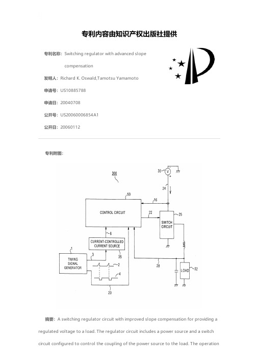
专利名称:Switching regulator with advanced slopecompensation发明人:Richard K. Oswald,Tamotsu Yamamoto申请号:US10885788申请日:20040708公开号:US20060006854A1公开日:20060112专利内容由知识产权出版社提供专利附图:摘要:A switching regulator circuit with improved slope compensation for providing a regulated voltage to a load. The regulator circuit includes a power source and a switch circuit configured to control the coupling of the power source to the load. The operationof the switch circuit is controlled by a control signal generated by a control circuit. A feedback circuit is provided for generating a feedback signal indicative of the regulated voltage provided by the switching regulator circuit to the load. A circuit is provided to generate a sensed signal indicative of the current supplied by the power source. The regulator circuit further includes a timing signal generator for generating a timing signal, a ramp signal generator for generating a ramp signal, and a current source controlled by the ramp signal for generating a compensation signal indicative of the ramp signal. The control circuit generates the control signal based on the compensation signal, the timing signal, the sensed signal and the feedback signal.申请人:Richard K. Oswald,Tamotsu Yamamoto地址:San Jose CA US,Cupertino CA US国籍:US,US更多信息请下载全文后查看。
罗莫(ROHM)产品用户指南说明书
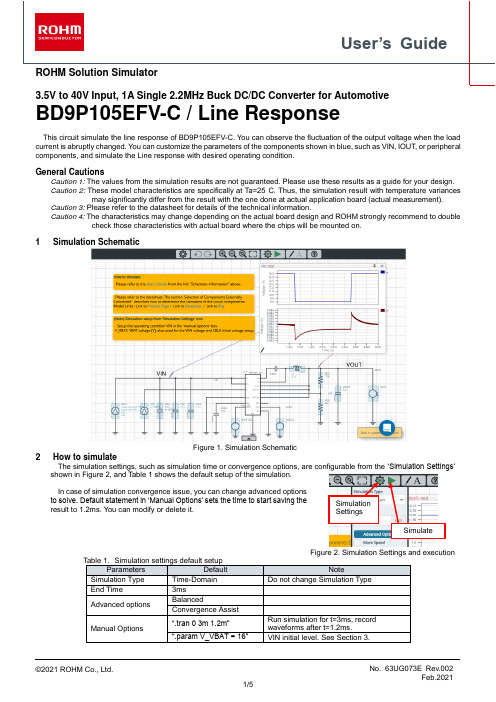
User’s GuideROHM Solution Simulator3.5V to 40V Input, 1A Single 2.2MHz Buck DC/DC Converter for AutomotiveBD9P105EFV-C / Line ResponseThis circuit simulate the line response of BD9P105EFV-C. You can observe the fluctuation of the output voltage when the load current is abruptly changed. You can customize the parameters of the components shown in blue, such as VIN, IOUT, or peripheral components, and simulate the Line response with desired operating condition.General CautionsCaution 1: The values from the simulation results are not guaranteed. Please use these results as a guide for your design. Caution 2: These model characteristics are specifically at Ta=25°C. Thus, the simulation result with temperature variancesmay significantly differ from the result with the one done at actual application board (actual measurement).Caution 3: Please refer to the datasheet for details of the technical information.Caution 4: The characteristics may change depending on the actual board design and ROHM strongly recommend to doublecheck those characteristics with actual board where the chips will be mounted on.1 Simulation SchematicFigure 1. Simulation Schematic2 How to simulateThe simulation settings, such as simulation time or convergence options, are configurable from the ‘Simulation Settings’ shown in Figure 2, and Table 1 shows the default setup of the simulation.In case of simulation convergence issue, you can change advanced options to solve. Default statement in ‘Manual Options’ sets the time to start saving the result to 1.2ms. You can modify or delete it.Figure 2. Simulation Settings and execution3 Simulation Conditions3.1 How to define VIN voltage (VBAT initial voltage and VEN setting)The VBAT initial voltage and the VEN voltage are set in the ‘Manual Options’ text box for parameter setting consistency.The voltage level of VBAT initial and VEN, and the initial voltage of CBLK refer to the variable V_VBAT. To define the voltage level, s et V_VBAT value in ‘.param’ sentence in the text box from ‘Simulation Settings’ > ‘Advanced Options’ as shown in Figure 3.‘Simulation Settings’Figure 3. Definition of VIN voltage.In order to secure the simulation stability those three parameters should be the same. So do not change those parameters respectively.3.2 VBAT parameter setupFigure 4 shows how the VBAT parameters correspond to the VIN stimulus waveform.(b) Magnified viewFigure 4.VIN parameters and its waveforms VOUT VOUT VIN VIN4 BD9P105EFV-C_Tran modelTable 3 and Table 4 shows the model terminal function implemented. Note that BD9P105EFV-C_Tran is the behavior model for its load/line response operation, and no protection circuits or the functions not related to the purpose are not implemented.(Note 3) This model is not compatible with the external synchronization function.(Note 4) Use the simulation results only as a design guide and the data reported herein is not a guaranteed value.4.1 Parameter TSSBD9P105EFV-C_Tran model has the property ‘TSS’, which is the soft start time described in page 7 of the datasheet.The product has 3ms (typical) of the startup time of the output voltage. You can short cut the soft start by changing TSS value. The default TSS value is set to 0.2ms in this simulation and you can modify the value in the property editor.Figure 5. TSS property of BD9P105EFV-C_Tran5 Peripheral Components5.1 Bill of MaterialTable 5 shows the list of components used in the simulation schematic. Each of the capacitor and inductor has the parameters of equivalent circuit shown below. The default value of equivalent components are set to zero except for the parallel resistance of L1. You can modify the values of each component.5.2 Capacitor Equivalent Circuits(a) Property editor (b) Equivalent circuitFigure 6. Capacitor property editor and equivalent circuit5.3 Inductor Equivalent Circuits(a) Property editor (b) Equivalent circuitFigure 7. Inductor property editor and equivalent circuitThe default value of PAR_RES is 6.6kohm.(Note 5) These parameters can take any positive value or zero in simulation but it does not guarantee the operation of the IC in any condition. Refer to the datasheet to determine adequate value of parameters.6 Link to the product information and tools6.1 Product webpage link: https:///products/power-management/switching-regulators/integrated-fet/buck-converters-synchronous/bd9p105efv-c-product6.2 Related documentsThe application notes are available from ‘Documentation’ tab of the product page.6.3 Design assist tools ar e available from ‘Tools’ tab of the product page.The Circuit constant calculation sheet is useful for deciding the application circuit constants.NoticeROHM Customer Support Systemhttps:///contact/Thank you for your accessing to ROHM product informations.More detail product informations and catalogs are available, please contact us.N o t e sThe information contained herein is subject to change without notice.Before you use our Products, please contact our sales representative and verify the latest specifica-tions :Although ROHM is continuously working to improve product reliability and quality, semicon-ductors can break down and malfunction due to various factors.Therefore, in order to prevent personal injury or fire arising from failure, please take safety measures such as complying with the derating characteristics, implementing redundant and fire prevention designs, and utilizing backups and fail-safe procedures. ROHM shall have no responsibility for any damages arising out of the use of our Poducts beyond the rating specified by ROHM.Examples of application circuits, circuit constants and any other information contained herein areprovided only to illustrate the standard usage and operations of the Products. The peripheral conditions must be taken into account when designing circuits for mass production.The technical information specified herein is intended only to show the typical functions of andexamples of application circuits for the Products. ROHM does not grant you, explicitly or implicitly, any license to use or exercise intellectual property or other rights held by ROHM or any other parties. ROHM shall have no responsibility whatsoever for any dispute arising out of the use of such technical information.The Products specified in this document are not designed to be radiation tolerant.For use of our Products in applications requiring a high degree of reliability (as exemplifiedbelow), please contact and consult with a ROHM representative : transportation equipment (i.e. cars, ships, trains), primary communication equipment, traffic lights, fire/crime prevention, safety equipment, medical systems, servers, solar cells, and power transmission systems.Do not use our Products in applications requiring extremely high reliability, such as aerospaceequipment, nuclear power control systems, and submarine repeaters.ROHM shall have no responsibility for any damages or injury arising from non-compliance withthe recommended usage conditions and specifications contained herein.ROHM has used reasonable care to ensur e the accuracy of the information contained in thisdocument. However, ROHM does not warrants that such information is error-free, and ROHM shall have no responsibility for any damages arising from any inaccuracy or misprint of such information.Please use the Products in accordance with any applicable environmental laws and regulations,such as the RoHS Directive. For more details, including RoHS compatibility, please contact a ROHM sales office. ROHM shall have no responsibility for any damages or losses resulting non-compliance with any applicable laws or regulations.W hen providing our Products and technologies contained in this document to other countries,you must abide by the procedures and provisions stipulated in all applicable export laws and regulations, including without limitation the US Export Administration Regulations and the Foreign Exchange and Foreign Trade Act.This document, in part or in whole, may not be reprinted or reproduced without prior consent ofROHM.1) 2)3)4)5)6)7)8)9)10)11)12)13)。
胃镜医师个人述职报告简短范文
胃镜医师个人述职报告简短范文英文回答:As a gastroenterologist specializing in endoscopy, I am pleased to present my personal performance report for the past year. Over the past twelve months, I have conducted over 500 upper endoscopies and 300 colonoscopies, achieving a success rate of over 95% in both procedures. I have also participated in several advanced endoscopy training courses to enhance my skills and keep up with the latest advancements in the field.One of my key achievements this year was successfully diagnosing and treating a patient with early-stage esophageal cancer during a routine endoscopy. The timely intervention not only saved the patient's life but also highlighted the importance of regular screenings for early detection of gastrointestinal diseases.In addition to my clinical work, I have activelyparticipated in research projects and presented my findings at several national and international conferences. One ofmy research projects focused on the use of artificial intelligence in improving the accuracy of polyp detection during colonoscopies, which received positive feedback from the medical community.I have also received positive feedback from my patients, with many expressing their satisfaction with my professionalism, expertise, and compassionate care.Building strong relationships with my patients andproviding them with personalized care has always been a top priority for me.In the coming year, I plan to further expand my skills by participating in advanced endoscopy training programsand continuing my research in the field of gastrointestinal endoscopy. I am committed to providing the highest quality care to my patients and contributing to the advancement of gastroenterology as a whole.中文回答:作为一名专注于内窥镜检查的胃肠病专家,我很高兴为过去一年的个人表现报告做出总结。
上海稳利达 三相单相全自动大功率补偿式稳压器-产品说明书
上海稳利达电气有限公司S H A N G H A I W E N L I D A E L E C T R I C C O ., L T D .上海稳利达科技股份有限公司S H A N G H A I W E N L I D A T E C H N O L O G Y .,L T D产品说明书Compensation AC stabilizerProduct descriptionSBW•DBW series automatic compensating alternative stabilizers are new products with voltage stable and protect functions, this product combining the mostadvanced European technology with our national condition.When the fluctuation of voltage occurs or load changes,it can automatically keep the stability of the output voltage.These series prod-ucts have the advantages of large capacity,high efficiency.small waveform deformation,smooth voltage regulation.wide range of load,the ability of undertaking instant overload,longterm continuous operation, manual & automatic control mode, protective function of overvoltage, short circuit and mechanical transmission failure.small volume and weight.easy and convenient usage,and reliable opera-tion.etc.These series products are widely used in the places requiring stable voltage such as in industry,agriculture,transportation,military, railway, postal offices, and scientific research institutes, which are includinglarge industrial production line, medical devices.architectural equipments.testing equipments,broadcast and TV stations, telecom statiions, air-conditional computer rooms, etc.Product descriptionChapter I overview1、TypeThis series of stabilizers' model shown in the figure:Rated capacity (KVA)Design StabilizerCompensating deviceS:three-phaseD:single-phaseB w2、Host machine and main components��Chapter I overview��Chapter I overviewSBW·DBW series stabilizer should be used indoors,normal conditions are as follows ① Temperature: -15~+45℃ ② Altitude: ≤1000m; ③ Relative Humidity: ≤90%;④ Installation position: no such materials serious effects on the Insulation of stabiliz-er, as gases,steam, chemical deposition, dust, dirt, and other explosive and erosive medium; ⑤ There is no serious fluctuation in installation position;⑥ If any of above conditions are not satisfied, it is suggested that user and WENLIDAarrange the installation.4、operation condition5、Working principles��Chapter I overviewStabilizer includes compensating circuit, voltage inspection circuit, feedback loop,servo-motor circuit and deceleration driving circuit, mainloop switch circuit,voltage and current measurement loop, and protection circuit.Three phase stabilizerSingle phase stabilizerInputOutput① When installing the stabilizer, the user should check in advance whether the grid line connected to the stabilizer is unblocked, including whether the contacts and sockets are in good contact, so as to avoid introducing open circuit or short-circuit faults.② When installing, pay attention to good grounding. If the mains input ground wire is floating, the input voltage between neutral and earth wire may reach 100V; if the user load has strict requirements for the neutral and earth wire voltage of the power supply system, please pay attention to the mains good grpounding to the mains good.③ When the user installs the stabilized power supply, do not connect the input and output neutral, live and earth wires of the stabilizer in reverse or wrong to avoid electrical short circuit; at the same time, check whether the input mains voltage is normal.④ Installation requirements for stabilizer:Place the stabilizer flat on the ground (avoid inclined, uneven ground).Do not place objects on top of the stabilizer, nor should anyone sit on it.Do not place it in a place containing corrosive gas.Chapter II installation and commissioningChapter II installation and commissioning1、Installation considerations2、On-site environmental requirements3、Display parameter setting① CleanSundries and rubbish should not be piled around the equipment. Droplets and metals dropped or placed inadvertently may cause short circuits and endanger the system and personal safety. Dust, dirt or debris on the equipment exhaust holes will hinder air circulation, thereby affecting the cooling effect of the fan. Cause the system to shutdown due to excessive temperature.The civil construction of the computer room should be completed, and the floor has been hardened. The site should be clean, dry and dust-free.② Fire protectionIt is strictly forbidden to store flammable and explosive hazardous materials in the equipment room.In order to reduce the possibility of fire and reduce the damage caused by this, the walls, ceiling and floor of the equipment room should be made of fire-resistant materials and equipped with suitable and effective fire-fighting equip-ment (e.g. portable CO2 fire extinguishers).③ Ventilation and heat dissipationIn order to facilitate operation and maintenance and heat dissipation of the equip-ment, at least 30-50cm should be left around the frame and 50cm should be left on theupper part.��Chapter II installation and commissioning① Display pictureChapter II installation and commissioningSETvoltage/phase voltage display.Press this button for 2 seconds to display the operating frequency and internaltemperature of the system. The left side is the frequency value, and the right side is ③ Display instructiong��Chapter II installation and commissioning⑥ Parameter setting descriptionP01P02P03P04P05P06P07Regulating accuracy Return voltage Overcurrent protection valueOvercurrent delayCurrent mutual inductance rdtio Overpressure upoer limit Overvoltage delayUpper and Umit Range Setting of Back-to-Middle voltage ValueOutput voltage setting valueWhen the actual phase current value is continuously greater than this item for x seconds,the over-current protetion function will beactivated when the maximun value is turned offThe actual current is continuously greater than the overcurrent protection value.After this delay, the overcurrent protection functionis activated The actual output line voltage value is continuously higher than this item after X seconds,the overcurrent protection functionbe activatedThe actual output line voltage value is continuously higher than this item after X seconds,the overcurrent protection functionis activated(unit/second)The range of external current sensor is from 25:5 to 2500:5P08 P09 P10 P11P12Undervoltage lower limitUndervoltage delayUnderpressure thresholdProtecion optionsRelay multiplexing settingsThe octual output line coltage volue is continusly less thon this itemfor X seconds,the undervoltage protection function will beactivatedThe octual voltage is continuously lower limit ofundervoltage protection after this delay (unit/second)(0-5) 10VSee protection instructions0.0:automatic judgment 0.1:fixed 50Hz 0.2:f ixed 60HzDelayed closing time of main output relay offer voltage stabilization(unit/second)1.Protection or alarm2.Main output controlDescription:1.Applicable to equipment knowledge input terminalwith electric operation device2.Applicable to equipment output terminal plus AC contactor (withstore line voltage stabilization and delay outpuut function)lnoperableVoltage Error Correction,Range Positive and Negative 6.0vVoltage Error Correction,Range Positive and Negative 6.0vVoltage Error Correction,Range Positive and Negative 6.0vVoltage Error Correction,Range Positive and Negative 6.0v Main output delayWorking frequency selectionCommunication station numberReverse phase detectionSystem settingsUAB voltage correction valueUBC voltage correction valueUCA voltage correction valueUab voltage correction valueP13 P14P15 P16 P17 P18 P19 P20 P21Optional node number with isolated Rs485communication interface0:reverse phase and open phase detection function off1:reverse phase and open phase detection function open*Chapter II installation and commissioningChapter II installation and commissioningThe range(0-5) 10V is 0V-50V,if it is set to 2,it is 20V.When the three-phase output sampling voltage is lower thar 20V,undervoltage will not be detected.The machine isnormal.Applicable to the three-phase output voltage sampling line connected behind the switch.Voltage Error Correction,Range Positive and Negative 6.0v Ubc voltage corrction value Uca voltage corrction value Fault record flag Voltage regulation setting Voltage Error Correction,Range Positive and Negative 6.0v 0:Clear alarm and record information 1:Record fault information completed 1:Manual voltage regulation 2:Automatic voltage regulationP22P23P24P2512345⑦ Protection setting descriptionOnly the overcurrent protection is enabled,and the overvoltage and undervoltage protection fucnctions are not enabled.After protection,the relay control is turned on/the main output is turned off,and it is restored manually.The overcurrent,overvoltage,and undervoltage protection starts.After protection,the relay control is turned on/the main output is not turned off,and it is restored manually.Overcurrent,overvoltage,and undervoltage protection starts.After the protection,the relay control is turned on/the main output is not turned off,ln the case of over-voltage protection and under-voltage protection,the voltage will be automatically restored if it is normal for 60 seconds.The overcurrent,overvoltage,and undervoltage protections are activated.After protection,the relay control is turned on/the main output is turned off,and it is restored manually.The overcurrent,overvoltage,and undervoltage protection starts.After the protection, the relay control is turned on/the main output is turned off.ln the case of over-voltage and under-voltage protection,the voltage will be automatically restored if it is normal for 60 seconds.⑧ Underpressure threshold setting instructions *⑨ Fault record viewing instructionsA/M bottom+down bottom simultaneously press for 1 second to enter Page 1: lnput UAB output Uab current lA fault statusPage 2: lnput UBC output Ubc current lB fault statusPage 3: lnput UCA output Ubc current lC fauilure status,press up and down to switch the page,A/M key to returm⑩ Fault record settingBecause only the information when the equipment fails in normal operation is stored,P2.4 will be set to 1 after saving,and it will also be set when the fault occurs again.No.data will be stored,You need to set P2.4 to 0 to save the information when the next failure occurs.(Recording information supports power-off save).⑪ Reverse phase and phase loss protection description When this function is turned on,the reverse ohase will only be detected once when the machine is turmed on.The phase sequence error lnput Voltage flashes and the phase loss detected in real time.No output voltage after protection.※lf any special type,please follow the instruction manual with the product.Chapter II installation and commissioning⑫ Wiring instructons and dimensions Rs485output voltage lnput voltageVoltage range:AC0-500V Power sampling input range 0-5Asupply AC 9-15V power 10W IC Ib Ia Uc Ub Ua UC UB UA A B Protection normally closed Protection nomally openBoost control Step-down control L or N input Maximum current 5A Please extemal insurance156mm 92mmBack view��Chapter II installation and commissioningFault diagnosis and maintenanceChapter III fault diagnosis and maintenance 1、Analysis of abnormal phenomena 2、Fault diagnosis ① Overview ② Fault diagnosis Phenomena Probable causeAfter turning on the power supply and setting the “emergency transfer switch” of the voltage stabilizer to “stabilizing”, the voltage stabilizer has no output.The voltage stabilizer cannot automati-cally switch to the mains output after an overvoltage or under voltage failure occurs.The voltage stabilizer cannot stabilize the voltage.The stabilizer cannot be turned on.When a fault occurs, first look for obvious damage and try to find out whether the fault is caused by the device itself or by the external environment (such as temperature, humidity, and load). Before deciding that your equipment is damaged, always check these external factors.This section only contains some simple fault diagnosis procedures. If the answer to the diagnosis is not very clear, or the information obtained is not sufficient to solve the problem, please refer to a professional or special maintenance station for processing After you enable the stabilizer, if it does not work normally, please do not rush to deter-mine that the stabilizer is malfunctioning. You may use following methods to solve theproblem.The phase sequence of the input power (reverse phase) is connected reversely or is missing phase The system detects that the input voltage is greater than ±10% of the rated voltage, and it is not allowed to automatically transfer to mains.1、The input power wiring is loose. Please check and tighten the power wiring. 2、The input voltage is greater than the voltage regulator range.Please check the input voltage.The "emergency transfer switch" is placed in the "bypass" position.Please place this switch in the "regulated" position.Fault diagnosis and maintenance3、Maintain Phenomenon descriptionProbable cause Solution The air switch in the regulator is not closed or damaged.The sampling transformer is damaged The control circuit board is damag Fuse blown① The voltage stabilizer is in a fault protection state ② The intermediate relay of the secondary circuit is damaged or the contactor on the main circuit is damaged Unable to bootUnable to stabilize switch on or replace the air switch.switch on or replace the air switch.① Check whether there are overvoltage, undervoltage and other faults ② Replace the corresponding components No output voltage ① Overview Correct maintenance, including preventive maintenance and remedial maintenance, is the key to optimal operation of the voltage stabilizer and will ensure a long service life of the equipment. Preventive maintenance includes some routines that are frequently performed. These procedures are used to prevent system failures and maximize operating efficiency. Remedial maintenance includes finding system failures for effective main-tenance. ② Safety precautions In order to perform system maintenance safely and successfully, the relevant safety precautions must be followed, the necessary tools and test equipment must be used, and qualified maintenance personnel must be involved. The following safety operat-ing procedures must be always observed:● Always remember that there is a dangerous voltage in the stabilizer, even if the stabilizer system is not running.Confirm that the voltage stabilizer operation and maintenance personnel must befamiliar with the equipment and the contents of this manual.● When operating the voltage stabilizer, do not wear gold or silver jewelry such as rings and watches.● Do not take the safety operation procedures for granted. If you have any questions, please consult the personnel familiar with the equipment.● Always be alert to the presence of dangerous voltage in the voltage stabilizer, and check with a voltmeter before maintenance and adjustment to ensure that the power is off and in a safe state.● Please strictly follow the user manual for use. When the voltage stabilizer fails, please do not handle it without authorization, and hand it to a professional or repair station.③ Preventive periodic maintenanceIn the process of use, regularly inspect the working status of the voltage stabilizer to check whether the temperature rise of the compensation transformer and the voltage regulating transformer is normal, whether the load exceeds the rated value, whether the input voltage exceeds the specifierange, whether the voltage regulating system and the transmission mechanism (including the transmission chain) work normally, whether the carbon brush holder is loose, whether the carbon brushes are on the same plane and in the same straight line, and whether the contact is good. None of the problems listed above is allowed to exist, so once it is found, it must be solved in time. If encounter difficult problems, you should notify the factory for solution in time to avoid damage to the equipment. It is recommended to maintain the voltage stabilizer every three months.The maintenance includes:● Eliminate dust and dirt from various parts of the stabilizer.● Check whether the electrical components are damaged, if damaged, they must be replaced in time.Fault diagnosis and maintenance上海市嘉定区高石公路 2439 号2439 Gaoshi highway, Jiading District, Shanghai邮政编码(Postal Code) 201816 传真(Fax):************网址(URL): 公司电话(TEL):************市场部电话(TEL):************-7后电话(TEL):800-820-3007产品说明书PRODUCT SPECIFICATION公司/上海稳利达电气有限公司 上海稳利达科技股份有限公司Company / Shanghai Wenlida Electric Co., Ltd. Shanghai Wenlida Technology Co., Ltd 印刷/上海视叶数码印刷有限公司Printing / Shanghai Shiye Digital Printing Co., Ltd 开本/148毫米×210毫米 32 开 印张/ 2 字数/ 5千Folio/148mm×210mm 32 open Printed Sheet/ 2 Words/ 5K 版次/2021 年 8 月第 1 版 2021 年 8 月第 2 次印刷Edition/First edition in August 2021 First printing in August 2021(如有设置、更换配件等需求可拨打以上任意电话联系,24小时服务)(If you need to set up or replace accessories, you can call any of the above numbers for 24-hour service)欢迎关注稳利达科技公众号2021年8月。
advanced functional materials的投稿模板
advanced functional materials的投稿模板Dear Editor,I would like to submit a research article entitled "Advanced Functional Materials for Enhanced Energy Storage and Conversion" for consideration for publication in Advanced Functional Materials.Title: Advanced Functional Materials for Enhanced Energy Storage and ConversionAbstract:This research article highlights the recent advancements in functional materials for energy storage and conversion applications. The article presents a comprehensive review of the wide range of materials available and their potential in various energy storage and conversion systems. It discusses the development of novel materials with improved properties, such as high energy density, long cycle life, fast charging and discharging rates, and improved safety. The article also addresses the challenges faced in implementing these materials in practical applications and proposes potential solutions.Introduction:The introduction provides an overview of the increasing demand for energy storage and conversion technologies to address the global energy crisis. It emphasizes the importance of functional materials in enhancing the performance and efficiency of these technologies. The introduction also outlines the objectives of the article and presents a brief overview of the content.Materials and Methods:This section describes the various advanced functional materials used for energy storage and conversion. It discusses their specific properties, synthesis methods, and characterization techniques. The section also includes a comparison of different materials and their suitability for different applications.Results and Discussion:This section presents the results of recent studies on advanced functional materials for energy storage and conversion. It highlights the improvements achieved in terms of energy density, cycle life, rate capability, and safety. The section also discusses the underlying mechanisms responsible for these improvements. Furthermore, it explores the potential applications of these materials in lithium-ion batteries, supercapacitors, fuel cells, and photovoltaic systems.Challenges and Future Perspectives:In this section, we identify and discuss the challenges associated with the implementation of advanced functional materials in practical energy storage and conversion systems. We propose potential solutions, such as the use of hybrid materials, innovative device architectures, and regulatory frameworks to address these challenges. Additionally, we provide insights into the future prospects and opportunities for further advancements in this field. Conclusion:The conclusion summarizes the key findings of the research article and emphasizes the significance of advanced functional materials for enhancing energy storage and conversion technologies. Itconcludes with a call for continued research and development in this area to accelerate the transition towards sustainable energy systems.Overall, we believe that this research article will be of great interest to the readers of Advanced Functional Materials, as it offers a comprehensive overview of the advancements in functional materials for energy storage and conversion. We look forward to hearing positive feedback from the reviewers and the opportunity to contribute to the journal.Sincerely,[Your Name][Your Affiliation][Contact Information]。
Advanced Test Equipment Corp. PalmSens4设备说明书
Rev. 1-2021-008Provided by: (800)404-ATECAdvanced Test Equipment Corp .®Rentals • Sales • Calibration • ServiceContentsPalmSens4: Compact, Versatile and Powerful (2)PSTrace: Software for Windows (4)PStouch: App for Android (5)PalmSens4 Measurement Specifications (6)PalmSens4 System Specifications (7)PalmSens4 EIS Contour Accuracy Plot (9)Optional BiPot specifications (10)Optional iR Compensation module specifications (10)Standard PalmSens4 Configuration (11)PalmSens4 accessories (12)PAGE | 1PAGE | 2PalmSens4: Compact, Versatile and PowerfulAvailable configurationsThe PalmSens4 is available with ±5V or ±10V DC-potential ranges and with different maximum frequencies for FRA / EIS. The following table shows the applicable product codes:Always a backupThe PalmSens4 is equipped with internal storage memory of 8 GB. This means all your measurements can automatically be saved on-board as backup. All internally stored measurements can be browsed and transferred back to the PC easily using PSTrace. Your data is always with your instrument wherever you take it.Not compatible with techniques: EIS, MultiStep and MixedModePAGE | 3Supported TechniquesThe PalmSens4 supports the following electrochemical techniques:Voltammetric techniques▪ Linear Sweep Voltammetry LSV ▪ Cyclic VoltammetryCV ▪ Fast Cyclic Voltammetry FCV ▪ AC VoltammetryACVPulsed techniques▪ Differential Pulse Voltammetry DPV ▪ Square Wave Voltammetry SWV ▪ Normal Pulse VoltammetryNPVAmperometric techniques▪ ChronoamperometryCA ▪ Zero Resistance Amperometry ZRA ▪ ChronocoulometryCC ▪ MultiStep Amperometry MA ▪ Fast AmperometryFAM ▪ Pulsed Amperometric DetectionPAD ▪ Multiple-Pulse Amperometric DetectionMPADGalvanostatic techniques▪ Linear Sweep Potentiometry LSP ▪ Chronopotentiometry CP ▪ MultiStep Potentiometry MP ▪ Open Circuit Potentiometry OCP▪ Stripping ChronopotentiometrySCP or PSAOther▪ Mixed ModeMM ▪Potentiostatic/Galvanostatic Impedance spectroscopyEIS/GEISo Potential scan or current scan o Fixed potential or fixed current o Time scanThese methods can all be used in their stripping modes which are applied for (ultra-) trace analysis.PAGE | 4PSTrace: Software for WindowsClick on a measurement inthe legend to see the available data and to generate more curves.Integration with third party software:▪ Excel ▪ Origin ▪ Matlab ▪ZViewSelect current ranges for auto ranging and the starting current range. Switch between plots if curves with different units are available.Measurement data and curvesOther functions in PSTrace 5 ▪ Equivalent Circuit Fitting▪ Scripting▪ Open your data in Origin and Excel with one click of a button▪ Save all available curves, measurement data and methods to a single file▪ Browse measurements on PalmSens4’s internal storage▪Direct feedback on method parametersMethod EditorClick on a curve in the legend to change its title or appearance.PAGE | 5PStouch: App for AndroidPStouch features: ▪ Setting up and running measurements ▪ Loading and saving measured curves ▪ Analysing and manipulating peaks▪ Sharing measurement data directly via any service like email or Dropbox▪ Concentration determination by means of Standard Addition or Calibration Curve▪ Support for PalmSens accessories such as a Multiplexer or Stirrer ▪All method and curve files are fully compatible with PSTrace software for Windows.For more information about our software visit:/softwarePStouch is an app for Android devices compatible with all PalmSens, EmStat and Sensit potentiostats.Works with PalmSens4 via USB (depending on the Android device) or wireless via Bluetooth.Download PStouch for free in the Google Play StorePalmSens4 Measurement SpecificationsThe following table shows limits for technique-specific parameters.1 PSTrace provides the option to measure forward and reverse currents separately.PAGE | 6PalmSens4 System SpecificationsPAGE | 7PAGE | 8PalmSens4 EIS Contour Accuracy PlotNoteThe accuracy contour plot was determined under lab conditions and should be used for referencepurposes. Please note that the true limits of an impedance measurement are influenced by allcomponents in the system, e.g. cables, the environment, and the cell.PAGE | 9Optional BiPot SpecificationsThe PalmSens4 can be expanded with a BiPot module for use with a second Working Electrode.Supported techniques for use with BiPot:▪ Linear Sweep Voltammetry ▪ Cyclic Voltammetry ▪ Chronoamperometry ▪ Multistep AmperometryOptional iR Compensation module specificationsiR Compensation for PalmSens4 is available as an in-factory add-on module.NoteThe BiPot module decreases the battery life of the PalmSens4 in idle mode (cell off) down to > 5 hours.Standard PalmSens4 ConfigurationA standard PalmSens4 includes a rugged carrying case with:▪ PalmSens4 ▪ USB cable ▪ Sensor cable ▪ 4 croc clips▪ PalmSens Dummy CellAlso included:▪ PSTrace software (on USB drive) ▪ Manual (hardcopy) ▪ Quick Start document ▪ Calibration reportOptionalo 7” Samsung tablet o Tablet chargerPalmSens4 sensor cable with croc clipsPalmSens4 standard configuration in case with accessories.PalmSens4 AccessoriesIn-factory add-on modulesBiPot moduleThe BiPot Module is an optional extension for thePalmSens4 and is for applications requiring controlof two independent working electrodes. Themodule fits inside the PalmSens instrument. ThePSTrace software supports this module for linearsweep, cyclic voltammetry and amperometricdetection with two working electrodes.See page 10 for BiPot specificationsiR Compensation moduleThe iR Compensation module is an optionalextension for the PalmSens4. The resistancebetween the reference electrode and the doublelayer of the specimen can cause a significantpotential drop, decreasing the applied potentialwhere it is required. The module provides positivefeedback to compensate for the iR-drop betweenReference electrode and the outside of the doublelayer of the electrochemical cell.See page 10 for iR Compensation modulespecificationsOther accessoriesMUX8-R2 or MUX16 multiplexerThe MUX8-R2 is an 8-channel multiplexer. It allowsthe PalmSens4 to measure up to 8 three-electrodecells or 8 sensors (2 or 3 electrode). In 8-WE modeit can measure up to eight working electrodes on sensor arrays with shared reference and counter electrodes. The MUX8-R2 is stackable.The MUX16 is a 16-channel multiplexer. It allows the PalmSens4 to measure up to 16 working electrodes with shared counter and reference electrodes.Magnetic stirrer with SwitchboxThe magnetic stirrer controlled by PalmSens is ideal for stripping analysis applications. The stirrer is switched on during the conditioning and deposition stages by means of the Switchbox.LM35/TMP36 temperature sensorThis temperature sensor allows for monitoring of temperature during an experiment.Two point calibration allows the user to precisely calibrate the sensor for the required temperature range. The calibration curve shows a linear slope of +10 mV/°C with 0.5°C Ensured Accuracy (at 25°C). It is rated for full 2°C to 150°C range (LM35) or -40°C to 125°C range (TMP36). The sensor has low self-heating (0.08°C in still air).Differential Electrometer Amplifier (DEA)The PalmSens Differential Electrometer Amplifier(DEA) is a high impedance input amplifier. It can beused as a floating voltage amplifier with differential input and single output to the auxiliary port of PalmSens devices.Default range is -10V to 10V (1x gain). Possible gains are: 2x, 5x, 10x, 20x, 50x and 100x.。
- 1、下载文档前请自行甄别文档内容的完整性,平台不提供额外的编辑、内容补充、找答案等附加服务。
- 2、"仅部分预览"的文档,不可在线预览部分如存在完整性等问题,可反馈申请退款(可完整预览的文档不适用该条件!)。
- 3、如文档侵犯您的权益,请联系客服反馈,我们会尽快为您处理(人工客服工作时间:9:00-18:30)。
International Conference on Renewable Energies and Power Quality (ICREPQ’10) Granada (Spain), 23rd to 25th March, 2010
1. Introduction
Active anti-islanding schemes inject additional disturbance into DG output and destabilize an islanded system so that the system frequency or voltage can deviate from the detection limits. There have been various active methods proposed [1]-[7]. Positive feedback methods based on dq- control have little NDZ, negligible power quality impact, and minimal implementation cost, and are also very robust to grid disturbances [7]. Such advantages are available when the positive feedback gains are optimally designed for certain purposes. This paper presents analytical methods for design of voltage positive feedback control. Design criteria are presented for meeting anti-islanding requirements of international standards and limiting power fluctuations owing to use of the active method. Gain design is considered for a constant-power controlled inverter (CPCI) and a constant-current controlled inverter (CCCI). Analytical expressions for lower and upper bounds of the VPF gain are derived by small signal and step response analysis, which derives that the conventional VPF control[7] significantly depends on output level of DGs. This means that anti-islanding effect and network disturbance impact varies with power output of an inverter, which makes it complicated to design an optimal gain. In order to remove real power dependence
( P * − Pin; (V −V ) K pf = iq s s +ω f K s − ( K p + i ) ∆Pinv + K pf ( ) ∆V = ∆iq s s +ωf
(1) (2)
For the system of (2) to be unstable, the positive feedback gain should meet the below inequality condition (3).
2.
DQ-based Voltage Positive Feedback
Key words
voltage positive feedback gain, dq control, anti-islanding, small signal stability
A. Concept of VPF in dq control Voltage positive feedback concept [7] can be applied into dq-based control as illustrated in fig. 1.
of the conventional scheme, a modified voltage positive feedback control is proposed. Digital time-domain simulation was carried out in PSCAD/ EMTDC, an electromagnetic transient analysis package, to validate the proposed design method. Simulation results show that the proposed analytical design is accurate and reliable.
Fig. 1. Voltage positive feedback in dq-frame
If inverter output voltage increases, VPF increases q-axis current resulting in more real power generation, which accelerates the initial voltage increase in islanding until the voltage will be eventually out of bounds for detection. When the inverter is connected to the grid, real power change caused by positive feedback will be absorbed by the grid, thus the resulting voltage variation will be normally negligible. In case that voltage decreases, the same operation mechanism will apply. B. Implementation of VPF in dq control DGs There are various types of inverters for grid connection of DGs. In this paper, a constant-power controlled inverter with synchronous rotating dq control structure is considered for VPF implementation. Fig. 2 shows the control schematic of a three-phase constant -power controlled inverter. Voltage positive feedback can be implemented as illustrated in fig. 3, where a proportional-integral (PI) controller is applied for real and reactive power control.
Advanced Voltage Positive Feedback Control for Anti-islanding of a Distribution Generation Inverter
S.-K. Kim1, J.-H. Jeon1, and H.-K. Choi1
Renewable Energy System Research Center Korea Electro-technology Research Institute, Changwon (Republic of Korea) Phone/Fax number:+82 55 280 1332, e-mail: blksheep@keri.re.kr
a few mili-seconds, thus in (1), the d-axis current command may be replaced by the actual current id. Linearization of (1) leads to small signal equation (2).
K pf >
Fig 2. Control Schematic of 3-phase grid inverter
6V K p + 2 R
(3)
Fig. 3. Voltage positive feedback controller
3. A.
Design of Voltage Positive Feedback Gain
1
Abstract.
the paper discusses an analytical design of dqbased voltage positive feedback (VPF) control for antiislanding of a distributed generation (DG) inverter. Design criteria for the voltage feedback gain are presented. Based on small signal stability and step response analysis, an analytical design method for lower and upper bounds of the gain is described. It is proven that conventional VPF gain is significantly influenced by real power levels of a DG. To improve this weakness, a modified VPF is proposed. Simulation study validates the analytical design method and the modified VPF control performance for a constant power- controlled inverters.