拉线式位移传感器说明书
拉线传感器
MPS拉绳/拉线位移传感器·电流信号(4-20MA)、电压信号(0-5V 0-10V)、脉冲输出(ABZ项,也可以根据您提供的编码器定制)·标准工业级、全金属封装,耐用型·适合中等距离精密直线或曲线位移测量·适合多种恶劣环境和苛刻工作条件,狭缝安装一、工作原理MPS型位移传感器将机械位移量转换成可计量的、成线性比例的电信号。
被测物体产生位移时,拉动与其相连接的钢绳,钢绳带动传感器传动机构和传感元件同步转动;当位移反向移动时,传感器内部的回旋装置将自动收回绳索,并在绳索伸收过程中保持其张力不变,从而输出一个与绳索移动量成正比例的电信号。
本品是基于微震动环境设计安装使用的产品。
二、主要特点MPS系列传感器的设计精密合理,采用高精密传感元件,传感器具有体积小,使用方便,密封性好,测量精度高,温度误差小,寿命长等优点。
该传感器不仅适宜于作直线运动的机械物体位移测量,更适宜于机械物体作曲线运动的位移测量。
三、主要技术指标1、位移有效测量范围:0-10000mm 6、工作方式:连续工作2、输入直流电压:+24VDC 7、工作温度:-25º-75ºC3、输出信号形式:4-20mA 8、制造材料:合金金属4、线性精度:优于±0.3%F.S 9、绳索材料:高柔性金属钢丝绳5、产品等级:标准工业级+ 10、重量:450g(实际重量随不同量程会有不同)11、表面处理:合金表面阳极化处理12电缆长度:1米13、小量程尺寸(60*66*76.5)中型量程尺寸(80*90*136)大型量程尺寸(164*152*158)四、接线电路五、使用注意事项1、安装拉线式位移传感器时,应根据被测点的运动轨迹,使拉线头拉出的拉绳尽量与传感器出口端面保持垂直。
利用底部4个固定螺丝孔,依现场及机器安装空间设施需要,直接安装或另加保护或其他机械使用,不锈钢索安装时,须注意水平角度,亦即尽量使钢索由出线口至移动部位之机构,于工作时水平滑动,保持最小角度(容许偏差+/-30)以确保量测精度及钢索之寿命,钢索本体是不锈钢加涂氟层,请勿让其受外力的割伤﹑烧损﹑撞击等不当之事发生:过量的粉尘﹑积屑或是足以破坏钢索的物品贮留于内部的滑轮或出线口将造成钢索破损,导致运转不顺的故障.2、未安装于工作台或固定坐前,请勿用手或是其它产品将钢索拉出并让其瞬间自行弹回.此举将造成钢索断裂,伤害本体结构及人身安全.当手动拉出传感器拉绳时,应轻轻送回拉线头,严禁松手使拉绳自动收回,否则,拉线头所受到的冲击加速度可能造成传感器损伤。
WAYCON 拉线式传感器安装指南说明书
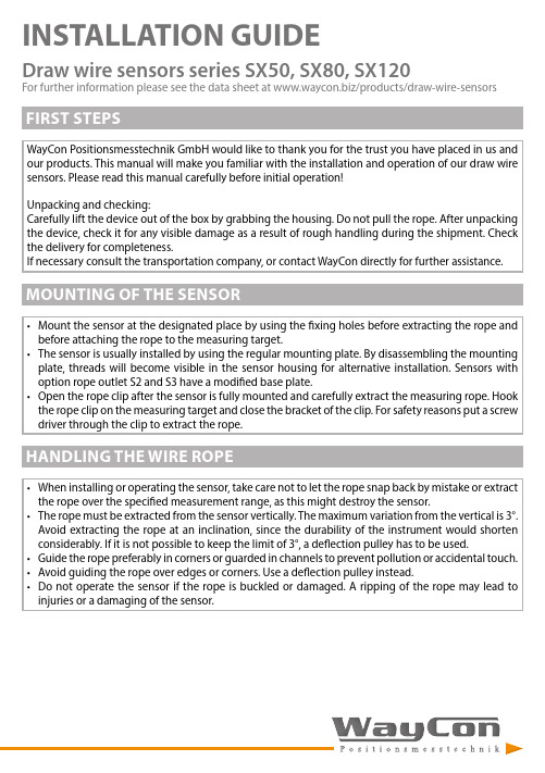
INSTALLATION GUIDEDraw wire sensors series SX50, SX80, SX120For further information please see the data sheet at /products/draw-wire-sensors• Mount the sensor at the designated place by using the fixing holes before extracting the rope and before attaching the rope to the measuring target.• The sensor is usually installed by using the regular mounting plate. By disassembling the mounting plate, threads will become visible in the sensor housing for alternative installation. Sensors with option rope outlet S2 and S3 have a modified base plate.• Open the rope clip after the sensor is fully mounted and carefully extract the measuring rope. Hook the rope clip on the measuring target and close the bracket of the clip. For safety reasons put a screw driver through the clip to extract the rope.• When installing or operating the sensor, take care not to let the rope snap back by mistake or extract the rope over the specified measurement range, as this might destroy the sensor.• The rope must be extracted from the sensor vertically. The maximum variation from the vertical is 3°. Avoid extracting the rope at an inclination, since the durability of the instrument would shorten considerably. If it is not possible to keep the limit of 3°, a deflection pulley has to be used.• Guide the rope preferably in corners or guarded in channels to prevent pollution or accidental touch.• Avoid guiding the rope over edges or corners. Use a deflection pulley instead.• Do not operate the sensor if the rope is buckled or damaged. A ripping of the rope may lead to injuries or a damaging of the sensor.WayCon Positionsmesstechnik GmbH would like to thank you for the trust you have placed in us and our products. This manual will make you familiar with the installation and operation of our draw wire sensors. Please read this manual carefully before initial operation!Unpacking and checking:Carefully lift the device out of the box by grabbing the housing. Do not pull the rope. After unpacking the device, check it for any visible damage as a result of rough handling during the shipment. Check the delivery for completeness.If necessary consult the transportation company, or contact WayCon directly for further assistance.M3 x 6Option S2Option S3Ø6Option S2Option S3ELECTRICAL CONNECTION INCREMENTAL OUTPUTELECTRICAL CONNECTION CAN openELECTRICAL CONNECTION E ther CAT, PROFINETWARNING NOTICES• Do not try to open the device. The stored energy of the spring drive may lead to injuries when being mishandled.• Do not touch the rope when operating the sensor.• When mounting outdoors protect the sensor and the rope from icing at temperatures below 0 °C. The usage of a deflection pulley may help defrosting the wire rope.• When operating the sensor in a humid environment, install the sensor with the rope outlet downwards. Otherwise water will gather inside the housing, which leads to corrosion. Where applicable use option S3.MAINTENANCEThe devices are maintenance-free. If however, the rope is soiled due to adverse environmental conditions, it can be cleaned with a cloth drenched in resin-free machine oil.DECLARATION OF EU-CONFORMITYManufacturer WayCon Positionsmesstechnik GmbH4M ehlbeerenstrasse/Germany82024TaufkirchenThis is to certify that the productsClassification draw wire sensorsProduct series SXfulfill the current request of the following EU-directives:EMC-directive 2004/108/EC (until April 19th, 2016)2016)20th,April2014/30/EU(fromstandards:appliedharmonized61326-1:2013IECThe declaration of conformity loses its validity if the product is misused or modified without proper authorisation.TägerTaufkirchen,Andreas24.02.2016CEO。
SX135系列03.08.23拉线传感器说明书

03.08.23DRAW WIRE SENSORLinks to further documents for this series:Installation guideManual for CANopenTeach electronics SqueezerData sheet TEDS connectorSX135 SERIES Key-Features:-Measurement ranges from 10 to 42.5 m-Analog output: potentiometer, voltage, current-Optional teachable voltage outputs-Digital Output Incremental: RS422 (TTL), Push-Pull-Digital Output Absolute: CANopen, SSI, Profibus,EtherCAT, Profinet-Linearity up to ±0.02% of full scale-Protection class up to IP67-Temperature range: -20...+85 °C (optional -40 °C)-High dynamics and interference immunity factor-Customised versions available-Optional with TEDS connectorContentTechnical Data Analog (2)Technical Data Incremental (3)Technical Data Digital WCAN (4)Technical Data Digital Absolute (5)Mechanical Data (6)Technical Drawing (6)Options (9)Accessories (10)Order Code (11)ELECTRICAL DATA ANALOG OUTPUT1)2) Load: 250 Ω (max. 500 Ω)3) Load max. 0.5 kΩ1)ELECTRICAL DATA DIGITAL OUTPUT INCREMENTALOUTPUT SIGNAL DIGITAL OUTPUT INCREMENTALELECTRICAL DATA DIGITAL OUTPUT ABSOLUTE CAN open(WCAN)ELECTRICAL DATA DIGITAL OUTPUT ABSOLUTE1)reduced to 60 % if option IP67 is used. The max. velocity is reduced to 3 m/s if option SP61 or SP62 is used.TECHNICAL DRAWING1351559,5ØA Xoutin 111,5YB C D Emoveable rope outletLength 11214218,5100*33 plugged50 plugged* For sensors with measurement ranges of 30 m or greater and radial connector output the encoder length is 120 mm instead of 100 mm.TECHNICAL DRAWING DIGITAL OUTPUT INCREMENTALStecker/connector radial M12Stecker/connector axial Stecker/connector axial Stecker/connector radial M23Kabel/cable radialKabel/cable axialTECHNICAL DRAWING DIGITAL OUTPUT ABSOLUTECANopen Profibus, Profinet, EtherCAT60Ø58Ø60Ø7649,576Standard for cable / connectorOption K2Option K3Option K1MOUNTING OPTIONS1. by using the grooves in the sensor housingThe included slot nuts can be easily inserted into the grooves of the sensor housing. The slot nuts have a metric M6 thread. Each sensor with a measurement range of 20 m or lower is delivered with two slot nuts. Each sensor 1775,510,6M 627115151515Mounting by using brackets165189OPTIONSØ20ø6,2Squeezer manual.-40...+80 °C6248,248209,5For bridging a greater distance between the measuring target and the sensor a rope extension can be applied. The rope clip must not be guided over the deflection pulley.ø 4312,52337Measurement range MR [m]10 / 12 / 15 / 20 / 25 / 30 / 35 / 40 / 42.5Output signalPotentiometer 1 kΩPotentiometer 5 kΩPotentiometer 10 kΩVoltage 0.5...4.5 V Voltage 0...5 VVoltage -5...+5 V Voltage 0...10 VVoltage 0...5 V (teachable) Voltage 0...10 V (teachable) Current 4...20 mA1R 5R 10R 4,5V 5V 55V 10V 5VT 10VT 420AConnectionConnector output M12, axial, 4 poles Connector output M12, radial, 4 poles Cable output, axial, 2 m, 4 poles Cable output, axial, 5 m, 4 poles Cable output, axial, 10 m, 4 poles 1)SA12 SR12 KA02 KA05 KA10Version StandardSensor with options -ODescription (see page 9)Improved linearity ±0.05 %Inverted output signalSynthetic wire rope (Coramid)Rope fixation M4Rope fixation eyeletCylindrical pinCylindrical pin with carbine ringProtection class IP67Corrosion protectionIncreased corrosion protectionIncreased temperature range -40...+85 °CSnapping protection (ranges 10 to 15)Snapping protection (ranges 20 to 42.5)TEDS: assembling 2)TEDS: assembling + programming 2)TEDS: assembling + programming +35 measurement points 2)OptionL05INCORM4RIZHZRIP67CPICPT40SP61SP62TDTDPTDPSNot combinable withT40CP, ICPCP, ICPCP, ICPCP, ICPICPM4, RI, ZH, ZR, ICPM4, RI, ZH, ZR, IP67, CPL05, SP61, SP62MR >15 m, CP, ICP, T40MR <20 m, CP, ICP, T401R, 5R, 10R, SA12, SR12, TDP, TDPS1R, 5R, 10R, SA12, SR12, TD, TDPS1R, 5R, 10R, SA12, SR12, TD, TDPOptionL05M4RIZHZRIP67CPICPT40SP61SP62TDTDPTDPS1) larger lengths on request2) for more information about TEDS connectors see here Bold text: standard with shorter lead timeMeasurement range MR [m]10 / 12 / 15 / 20 / 25 / 30 / 35 / 40 / 42.5Resolution [Pulses/mm]0.3 / 3 / 6 / 15Output signalLine driver RS422 (TTL) Push-Pull (HTL)L GConnectionConnector output M23, radial, 12 pins Connector output M23, axial, 12 pins Connector output M12, radial, 8 pins Connector output M12, axial, 8 pins Cable output, radial, 2 m 1)Cable output, radial, 5 m 1)Cable output, radial, 10 m 1), 2)Cable output, axial, 2 m 1)Cable output, axial, 5 m 1)Cable output, axial, 10 m 1), 2)SR23 SA23 SR12 SA12 KR02 KR05 KR10 KA02 KA05 KA10Version StandardSensor with options -ODescription (see page 9)Cable/connector orientation topCable/connector orientation leftCable/connector orientation bottomImproved linearity ±0.02 %Synthetic wire rope (Coramid)Rope fixation M4 threadRope fixation eyeletCylindrical pinCylindrical pin with carbine ringProtection class IP67Corrosion protectionSnapping protection (ranges 10 to 15)Snapping protection (ranges 20 to 42.5)OptionK1K2K3L02CORM4RIZHZRIP67CPSP61SP62Not combinable withResolution 0.3/3CPCPCPCPM4, RI, ZH, ZRMR >15 m, CPMR <20 m, CPOptionL02M4RIZHZRCPSP61SP621) Line driver: 10 poles / Push-Pull: 8 poles2) larger lengths on requestBold text: standard with shorter lead timeSX135Measurement range MR [m]10 / 12 / 15 / 20 / 25 / 30 / 35 / 40 / 42.5Output signalCANopen WCANConnectionConnector output M12, axial, 5 poles Connector output M12, radial, 5 poles Cable output, axial, 2 m, 5 poles Cable output, axial, 5 m, 5 poles Cable output, axial, 10 m, 5 poles 1)SA12 SR12 KA02 KA05 KA10Version StandardSensor with options -ODescription (see page 9)Synthetic wire rope (Coramid)Rope fixation M4Rope fixation eyeletCylindrical pinCylindrical pin with carbine ringProtection class IP67Corrosion protectionIncreased corrosion protectionIncreased temperature range -40...+85 °CSnapping protection (ranges 10 to 15)Snapping protection (ranges 20 to 42.5)OptionCORM4RIZHZRIP67CPICPT40SP61SP62Not combinable withCP, ICPCP, ICPCP, ICPCP, ICPICPM4, RI, ZH, ZR, ICPM4, RI, ZH, ZR, IP67, CPMR >15 m, CP, ICP, T40MR <20 m, CP, ICP, T40OptionM4RIZHZRIP67CPICPSP61SP621) larger lengths on requestMeasurement range MR [m]10 / 12 / 15 / 20 / 25 / 30 / 35 / 40 / 42.5Output signal SSI CANopen Profibus DP EtherCAT ProfinetSSI CAN PRO CAT NETConnectionConnector M12, radial, 8 pins (SSI) Connector M23, radial, 12 pins (SSI)Cable output, radial, 1 m, PVC (SSI)Cable output, radial, 5 m, PVC (SSI)Cable gland, radial (CAN, PRO) 1) Connector 2 x M12, radial, 5 pin (CAN) 1) Connector 3 x M12, radial, 5 pin (PRO) 1) Connector 3 x M12, radial, 4 pin (CAT, NET) 1)SR12 SR23 KR01 KR05 KVBH SR12 SR12 SR12Version StandardSensor with options -ODescription (see page 9)Cable/connector orientation topCable/connector orientation leftCable/connector orientation bottomSynthetic wire rope (Coramid)Rope fixation M4 threadRope fixation eyeletCylindrical pinCylindrical pin with carbine ringProtection class IP67Corrosion protectionSnapping protection (ranges 10 to 15)Snapping protection (ranges 20 to 42.5)OptionK1K2K3CORM4RIZHZRIP67CPSP61SP62Not combinable withCPCPCPCPM4, RI, ZH, ZRMR >15 m, CPMR <20 m, CPOptionM4RIZHZRCPSP61SP621) removable bus terminal coverUR2deflection pulley (for rope diameter 0.5 mm) MGG1magnetic clampRCS-SX135 1)rope cleaner SV1-XXXX rope extension (150 mm up to 4995 mm) SV2-XXXX rope extension (5000 mm up to 19995 mm) SV3-XXXX rope extension (20000 mm up to 40000 mm)1) please note that the maximum measuring range is reduced by 29 mm when using the rope cleaner. The RCS is not compatible with the option RI.Cable with connector (female) M12, 4 poles, shielded, IP67 K4P2M-S-M12 2 m, straight connectorK4P5M-S-M12 5 m, straight connectorK4P10M-S-M1210 m, straight connectorK4P2M-SW-M12 2 m, angular connectorK4P5M-SW-M12 5 m, angular connectorK4P10M-SW-M1210 m, angular connector Mating connector (female) M12, 4 poles, for self assembly D4-G-M12-S straight connectorD4-W-M12-S angular connectorConnection cable sensor to Squeezer (female to male)K4P1,5M-SB-M12 1.5 m, shielded, 4 polesDigital displays for sensors with analog output, 2 channelWAY-AX-S touch screen, supply: 18...30 VDCWAY-AX-AC touch screen, supply: 115...230 VACFor more information and options please refer to the WAY-AX data sheet.Teach accessories for VT outputsSQUEEZER2M accessory for VT output, 2 m cable SQUEEZER5M accessory for VT output, 5 m cable SQUEEZER10M accessory for VT output, 10 m cableCable with connector (female) M12, 8 poles, shielded, IP67 K8P2M-S-M12 2 m, straight connectorK8P5M-S-M12 5 m, straight connectorK8P10M-S-M1210 m, straight connectorK8P2M-SW-M12 2 m, angular connectorK8P5M-SW-M12 5 m, angular connectorK8P10M-SW-M1210 m, angular connector Cable with connector (female) M23, 12 poles, shielded, IP67 K12P2M-S-M23 2 m, straight connectorK12P5M-S-M23 5 m, straight connectorK12P10M-S-M2310 m, straight connectorMating connector (female) M12, 8 poles, for self assembly D8-G-M12-S straight connectorD8-W-M12-S angular connector Mating connector (female) M23, 12 poles, for self assembly CON012-S straight connector, metal housingDigital displays for sensors with HTL output, 2 channelWAY-DX-S touch screen, supply: 18...30 VDCWAY-DX-AC touch screen, supply: 115...230 VACFor more information and options please refer to the WAY-DX data sheet.Digital displays for sensors with HTL or TTL output, 2 channelWAY-DXM-S touch screen, supply: 18...30 VDCWAY-DXM-AC touch screen, supply: 115...230 VACFor more information and options please refer to the WAY-DXM data sheet.Cable with connector (female) M12, 5 poles, shielded, IP67 K5P2M-S-M12 2 m, straight connectorK5P2M-SW-M12 2 m, angular connectorSubject to change without prior notice.WayCon Positionsmesstechnik GmbH Email: ************** Internet: Headquarters MunichMehlbeerenstr. 482024 TaufkirchenTel. +49 (0)89 67 97 13-0Fax +49 (0)89 67 97 13-250Office CologneAuf der Pehle 150321 BrühlTel. +49 (0)2232 56 79 44Fax +49 (0)2232 56 79 45Cable with connector (female) M12, 8 poles, shielded, IP67 K8P2M-S-M12 2 m, straight connectorK8P5M-S-M12 5 m, straight connectorK8P10M-S-M1210 m, straight connectorK8P15M-S-M1215 m, straight connector Cable with connector (female) M23, 12 poles, shielded, IP67 K12P2M-S-M23 2 m, straight connectorK12P5M-S-M23 5 m, straight connectorK12P10M-S-M2310 m, straight connectorK12P15M-S-M2315 m, straight connectorMating connector (female) M12, 8 poles, for self assembly D8-G-M12-S straight connectorD8-W-M12-S angular connector Mating connector (female) M23, 12 poles, for self assembly CON012-S straight connector, metal housingDigital displays for sensors with SSI output, 2 channelWAY-SX-S touch screen, supply: 18...30 VDCWAY-SX-AC touch screen, supply: 115...230 VACFor more information and options please refer to the WAY-SX data sheet.open (CAN) Cable with connector M12, 5 poles, shielded, IP67K5P2M-B-M12-CAN 2 m, female connector to open endsK5P2M-SB-M12-CAN 2 m, female connector to male connectorK5P2M-S-M12-CAN 2 m, male connector to open endsCable with connector M12, 5 poles, shielded, IP67K5P2M-B-M12-PROF 2 m, female connector to open endsK5P2M-SB-M12-PROF 2 m, female connector to male connector K5P2M-S-M12-PROF 2 m, male connector to open endsOtherM12-PROF-AW termination resistor therCable with connector (male) M12, 4 poles, shielded, IP67 K4P2M-S-M12-CAT 2 m, straight connectorK4P5M-S-M12-CAT 5 m, straight connectorK4P10M-S-M12-CAT10 m, straight connector Cable with connector M12, 4 poles, shielded, IP67K4P2M-SS-M12-CAT 2 m, male connector to male connector K4P5M-SS-M12-CAT 5 m, male connector to male connector K4P10M-SS-M12-CAT10 m, male connector to male connectorPlease note, that an additional cable is required for the power supply. Appropriate cables can be chosen from the list of the …Accessories Analog Output“.。
MFB-MPSFS1 拉绳位移传感器使用说明书
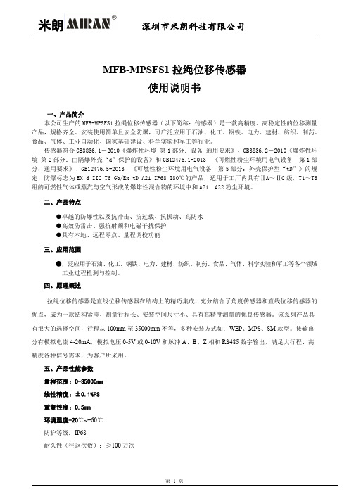
MFB-MPSFS1拉绳位移传感器使用说明书一、产品简介本公司生产的MFB-MPSFS1拉绳位移传感器(以下简称:传感器)是一款高精度、高稳定性的位移测量产品,规格齐全、安装使用简单且安全防爆,可广泛应用于石油、化工、钢铁、电力、建材、纺织、制药、食品、气体、工业自动化、国家基础建设、科学实验和军工等行业。
传感器符合GB3836.1-2010《爆炸性环境第1部分:设备通用要求》、GB3836.2-2010《爆炸性环境第2部分:由隔爆外壳“d”保护的设备》和GB12476.1-2013《可燃性粉尘环境用电气设备第1部分:通用要求》、GB12476.5-2013《可燃性粉尘环境用电气设备第5部分:外壳保护型“tD”》的规定,防爆标志为EX d IIC T6Gb/Ex tD A21IP68T80℃的产品,适用于工厂内具有ⅡA~ⅡC级,T1~T6组的可燃性气体或蒸汽与空气形成的爆炸性混合物的环境中和A21A22粉尘环境。
二、产品特点●卓越的防爆性以及抗冲击、抗过载、抗振动、高防水●高效防雷击、强抗射频和电磁干扰保护●具有本地、远程零点、量程调校功能三、应用范围●广泛应用于石油、化工、钢铁、电力、建材、纺织、制药、食品、气体、科学实验和军工等各个领域工业过程检测与控制。
四、原理概述拉绳位移传感器是直线位移传感器在结构上的精巧集成,充分结合了角度传感器和直线位移传感器的优点,成为一款结构紧凑、测量行程长、安装空间尺寸小、具有高精度测量的优良传感器。
该系列产品具有很大的选择空间,行程从100mm至35000mm不等,多种安装方式如:WEP、MPS、SM款型。
按输出分有模拟电流4-20mA,模拟电压0-5V或0-10V和脉冲A、B、Z相和RS485数字输出,满足大行程、高精度各种信号需求,为客户所采用。
五、产品性能参数量程范围:0-35000mm线性精度:±0.1%FS重复性度:0.5mm环境温度-20℃~+60℃防护等级:IP68耐久性(往返次数):≥100万次防爆标志:Ex d IIC T6Gb/Ex tD A21IP68T80℃六、产品安装尺寸图七、安装说明传感器必须按照GB/T3836.15-2017《爆炸性环境第15部分:电气装置的设计、选型和安装》的有关要求进行安装。
开思科技KS60S系列拉绳位移传感器说明书
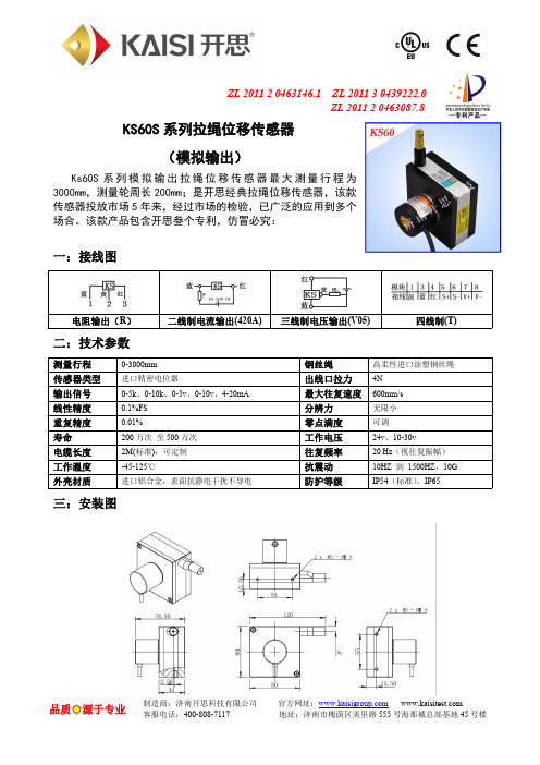
ZL 201120463146.1ZL 201130439222.0ZL 201120463087.8KS60S 系列拉绳位移传感器(模拟输出)Ks60S 系列模拟输出拉绳位移传感器最大测量行程为3000mm,测量轮周长200mm;是开思经典拉绳位移传感器,该款传感器投放市场5年来,经过市场的检验,已广泛的应用到多个场合。
该款产品包含开思叁个专利,仿冒必究:一:接线图电阻输出(R )二线制电流输出(420A)三线制电压输出(V05)四线制(T)二:技术参数测量行程0-3000mm 钢丝绳高柔性进口涂塑钢丝绳传感器类型进口精密电位器出线口拉力4N 输出信号0-5k 、0-10k 、0-5v 、0-10v 、4-20mA 最大往复速度600mm/s 线性精度0.1%FS 分辨力无限小重复精度0.01%零点满度可调寿命200万次至500万次工作电压24v 、10-30v电缆长度2M(标准),可定制往复频率20Hz (视往复振幅)工作溫度-45-125℃抗震动10HZ 到1500HZ ,10G 外壳材质进口铝合金,表面抗静电干扰不导电防护等级IP54(标准),IP65三:安装图四:注意事项1.安装时要使拉线垂直拉线编码器,不能让线摩擦出线口;2.拉绳位移传感器拉线安装头和设备移动端要可靠安装,防止长时间运行松动,自由弹簧;3.拉线头拉出后请不要松开,这样会造成传感器损坏,拉线时请勿超出线总长;4.电气连接请安装位移传感器上的接线说明接线,要保证接线正确才能通电;5.拉线位移传感器属于精密仪器请勿敲击,保证设备和钢丝绳清洁,延长使用寿命;6.要保护好钢丝绳不受外力损伤;7.室外或者环境比较恶劣的环境,请咨询开思防水防尘出线口或防护外壳;五:预延伸方案如果测试的距离很小,中间的安装距离比较大,由于安装部分长度不参与测量,那么就没有必要选择行程比较大的位移传感器,采用传感器外加延长线的方式解决,可以增加传感器的测试精度和减少费用,具体技术问题请在订货前告诉我们的客户经理,我们会在产品生产中给您解决这个问题。
拉线式位移传感器DT-C说明书
DT-C拉线位移传感器DT-C拉线位移传感器使用明使用该产品之前使用该产品之前,,请仔细阅读本说明书特点::一、特点●安装方便●测量范围大:最大可达50m●零点满量程可调●高强度拉线,抗污染能力强工作原理::二、工作原理DT-C通过精密的机械结构,始终保持绕线的均匀排布,并有旋力弹簧,保持拉线绷紧,并有足够的回缩力。
机械位移,使拉线变化带动轴旋转,高精密电位器同轴旋转产生电阻变化;再通过变送器将电阻信号转化成标准的电流或电压信号输出。
技术参数::三、技术参数量程:50mm~2.Om2.5m~50.8m测量精度:2~5〞±0.3FS15~25〞±0.2%FS其余量程:±0.15%FS输出方式:0~10V或4~20mA(由客户订货时指定)输出负载阻抗:>5000Ω(电压输出方式)<1000Ω(电流输出方式)工作电压:12~35VDC绝缘阻抗:100VDC时,100MΩ重复性误差:±0.15%FS适用温度:-25~80℃密封等级:IP65四、调整方法:先按图1将变送器的插头引线之后。
按图2所示接线。
出厂时,已调整好输出。
在现场如有需要改变零点、满量程的输出,可用小号一字小螺丝刀通过如图3所示的调整孔(“ZERO”为调整零点,“SPAN”为调整满量程)分别调整零点、满量程对应的电位器而改变输出量程。
使两根供电电源线上产生4-20mA的电流变化,对应为:零点为4.00mA,满量程为20.00mA(电流型输出时)。
零点为0V,满量程为10.00V(电压型输出时)五、接线图:1.电流输出方式:2.电压输出方式:图1变送器插头接线图图2变送器接线图图3变送器顶视图注意事项::六、注意事项1、拉线拉长后,不能突然撒手回弹,否则绕线排布不均,造成测量不准。
2、裸线表面忌油漆类污染干结,损坏滤塞。
七、维护1.该变送器结构简单,现场免维护。
2.校验须按前面介绍步骤处理。
15 直线位移(拉绳)传感器

直线位移(拉绳)传感器(WXY31-1010-S2)拉绳式位移传感器将机械位移量转换成可计量的、成线性比例的电信号。
被测物体产生位移时,拉动与其相连接的钢绳,钢绳带动传感器传动机构和传感元件同步转动;当位移反向移动时,传感器内部的回旋装置将自动收回绳索,并在绳索伸收过程中保持其张力不变,从而输出一个与绳索移动量成正比例的电信号。
我们通过标定,计算出K 值(系数),就可以得到相应的位移值。
该类型直线位移传感器广泛应用于机电设备、工程设备、港口及水利设备等,例如注塑机、钻管机、升降机、龙门吊、水闸开度等。
规格/特点:●类型:模拟量输出; ●检测方式:精密电位器型,绝对位置采集; ●电压输出型:0-5v ; ●工作电压:DC12~24V ; ●线性精度:0.1%FS ●重复精度:0.01%; ●分辨率:理论无穷小; ●最大往复速度:300mm/s ; ●测量行程:0-1000mm ; ● 防护等级:IP54引脚定义:工作原理:拉绳位移传感器的功能是把机械运动转换成可以计量,记录或传送的电信号。
拉绳位移传感器由可拉伸的不锈钢绳绕在一个有螺纹的轮毂上,此轮毂与一个精密旋转感应器连接在一起,感应器可以是增量编码器,绝对(独立)编码器,混合或导电塑料旋转电位计,同步器或解析器。
操作上,拉绳式位移传感器安装在固定位置上,拉绳缚在移动物体上。
拉绳直线运动和移动物体运动轴线对准。
运动发生时,拉绳伸展和收缩。
一个内部弹簧保证拉绳的张紧度不变。
带螺纹的轮毂带动精密旋转感应器旋转,输出一个与拉绳移动距离成比例的电信号。
测量输出信号可以得出运动物体的位移、方向或速率。
圆端子 棕线 蓝线 黑线传感器尺寸:安装注意事项:●安装时要使拉线垂直编码器,不能让线摩擦出线口。
●线编码器拉线安装头和设备移动端要可靠安装,防止长时间运行松动,禁止自由回弹。
●拉线头拉出后请不要松开,这样会造成传感器损坏,拉线时请勿超出线总长。
●通电前,请确认接线是否正确(按照拉线位移编码器上的接线说明接线)。
拉绳式位移传感器安全操作及保养规程

拉绳式位移传感器安全操作及保养规程拉绳式位移传感器是一种常用于工业控制、机械测量等领域的传感器。
在使用过程中,正确的操作和保养可以更好地保障其性能和使用寿命,同时也可以确保操作者和设备的安全。
本文将介绍拉绳式位移传感器的安全操作和保养规程。
一、安全操作规程1. 机器停止运转后再进行操作在进行拉绳式位移传感器的安装、调试、维护等操作时,一定要确保机器已经停止运转,开关已经关闭,电源已经断开,以免误操作造成人员和设备的损失。
2. 确保拉绳的正确安装在使用拉绳式位移传感器时,要确保拉绳正确安装到被测物体上,并且拉绳的拉力要均匀分布,避免单点过载导致传感器损坏。
3. 避免过度拉伸拉绳式位移传感器的最大允许拉伸长度是其标称长度的120%,过度拉伸会导致传感器的性能降低或者完全失效。
因此,在使用该传感器时要注意不要超过最大拉伸长度。
4. 避免超负荷在使用拉绳式位移传感器时,要确保被测物体的质量不超过传感器的额定负荷,否则会导致传感器失效或者破裂,造成人员和设备损失。
5. 避免过度震动拉绳式位移传感器在使用时要避免过度震动,避免对传感器产生不良影响,可以通过适当减震或者改变被测物体的结构等方式来避免过度震动。
6. 避免水、油、腐蚀物质的侵入在使用拉绳式位移传感器时,要避免水、油、腐蚀物质等物质的侵入,因为这些物质会对传感器的性能造成不良影响。
可以通过密封传感器或者将传感器和这些物质隔离的方式来避免它们的侵入。
7. 避免碰撞和摩擦拉绳式位移传感器在使用时要避免碰撞和摩擦,避免对传感器产生损坏。
可以通过适当加装保护装置或者改变被测物体的结构等方式来避免碰撞和摩擦。
8. 定期检查传感器的工作状况拉绳式位移传感器在使用一段时间后,会因为各种原因导致性能下降或者失效。
因此,在使用过程中要定期检查传感器的工作状况,发现问题及时处理,以免发生危险事故。
二、保养规程1. 定期清洁拉绳式位移传感器在使用过程中会因为环境污染等原因,积累一定的灰尘和污垢,因此要定期清洁。
- 1、下载文档前请自行甄别文档内容的完整性,平台不提供额外的编辑、内容补充、找答案等附加服务。
- 2、"仅部分预览"的文档,不可在线预览部分如存在完整性等问题,可反馈申请退款(可完整预览的文档不适用该条件!)。
- 3、如文档侵犯您的权益,请联系客服反馈,我们会尽快为您处理(人工客服工作时间:9:00-18:30)。
接线图 (适用于拉绳式位移传感器)
安装尺寸:
安装注意事项
1.利用底部4个固定螺丝孔,依现场及机器安装空间设施需要,直接安装或另加保护或其他机械使用. 2.不锈钢索安装时,须注意水平角度,亦即尽量使钢索由出线口至移动部位之机构,于工作时水平滑动.
保持最小角度(容许偏差+/-3.
)以确保量测精度及钢索之寿命.
3.钢索本体是覆盖(coating)一层氟(fluorin),请勿让其受外力的割伤﹑烧损﹑撞击等不当之事发生:过量的粉尘﹑积屑或是足以破坏钢索的物品贮留于内部的滑轮或出线口将造成钢索破损,导致运转不顺的故障.
4.在产品未安装于工作台或固定坐前,请勿用手或是其它产品将钢索拉出并让其瞬间自行弹回.此举将造成钢索断裂,伤害本体结构及人身安全.
5.MPS-S-P 和MPS-M-P 系列产品的往复运动的瞬间加速绝对不可超过1米/秒;MPS-L-P 和MPS 系列产品的往复运动的瞬间加速绝对不可超过0.5米/秒;此举将造成钢索断裂,恕本公司不承担此范围以外的责任. 6.若使用于非直线运动的机构,请加装适当的滑轮运转.
若使用于环境恶劣或特殊场合,请自行加装保护机构或与本公司工程部﹑经销商洽谈,否则造成产品损坏,本公司不予以负责.
7.三线制电流信号务必先接好负载后再通电使用。
否则会导致产品过载损坏. 参考网址:
拉线式位移传感器
MIRAN
R
使用操作手册
电阻输出型 棕色
蓝色 黑色 ① ② ③ 棕色 +5/+10VDC 黑色
0V/GROUND N 蓝色 OUTPUT 模拟信号 4-20mA 输出型(三线制)
MPS
棕色 黑色
1□棕色 12-24VDC 2□蓝色 0V
模拟信号 0-5V/10V 输出型 脉冲信号 输出型
蓝色
3□黑色 OUTPUT(4-20MA)
屏蔽线 GROUND
MPS
BROWN
BLUE
BLACK
1□ 棕色 12-24VDC 2□ 蓝色 0V 3□黑色 OUTPUT(0-5/10VDC) 屏蔽线 GROUND
MPS
BLUE
BROWN BLACK
1□ 红色 5-24VDC 2□ 黑色 0V 3□绿色:A
屏蔽线 GROUND
屏蔽线 GROUND
M
L S
4□黄色:B 5□蓝色:Z
模拟信号 4-20mA 输出型(二线制)
MPS 棕色
黑色
1□棕色 12-24VDC
3□黑色 OUTPUT(4-20MA)。