DH-CG300使用说明书
CG300多功能控制器操作说明
重新设定量程或者清除多余的物料,保证最大计量的物料不超过设定的量程
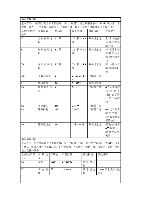
t2
卸料延迟时间
3.0秒
0.1秒-9.9秒
数字设定键
卸料到零位范围以后延迟此时间关门
T3
延迟启动时间
2.0秒
0.1秒-9.9秒
数字设定键
下一罐料启动的间隔时间
d.p
小数点选择
0
0、1、2、3、4
“配置”键
PL
零点跟踪
U
卸料控制方式
0
0、1
“配置”键
0表示用线控按钮盒控制;1表示用行程开关控制
常见故障处理
左侧数码管显示
故障定义
故障原因
排除措施
E1
校秤错误
1.传感器接线不正确
检查传感器接线,重新校秤后仍显示E1,更换传感器
2.校秤操作不正确
重新进行校秤操作
3.控制器故障
返厂维修
E2
设定值不正确
设定值总和超量程或者定值大于落差
重新输入设定值或修改落差
OL
超量程
1.还未进行校零、校秤操作
按步骤进行校零和校秤
基本参数列表
进入方法:在控制器处于停止状态时,按下“配置”,通过数字键输入“1616”键入第一个参数;进入下一个参数,再次按下:“确认”键、按下“定值”键随时退出设置并保存
左侧数码管显示
参数定义
默认值
设置范围
修改按键
参数说明
t1
上料间隔时间
2.0秒
0.1秒-9.9秒
数字设定键
上料门关闭后的稳定延迟时间
设定值及落差
进入方法:在控制器处于停止状态时,按下“定值”按键,进入定值设定操作:再次按下“定值”键随时退出设置并保存。
基于MATLAB的球面干涉仪图像处理系统设计
基于MATLAB的球面干涉仪图像处理系统设计兰明强;林健;王敏;詹明媚【摘要】A kind of non-contact online spherical interferometer has been designed and developed with Twyman-Green interferometry principle in the laboratory. The CCD camera lens in this interferometer can produce relatively high resolution image of the interence fringe. This paper mainly focuses on the basic method for using MATLAB image processing software to digitize the interference fringe, and through the pretreatment of this interference fringe and the extraction of the skeleton, finally the wavefont function of the detected spherical surface was fitted by adopting the Zernike polynomial; through the MATLAB programming, the automated processing of the detection signal of this spherical interferometer was realised.%采用泰曼一格林干涉原理设计研制了一种非接触在线球面干涉仪,该干涉仪中的CCD摄像头可产生分辨率比较高的干涉条纹图像.重点介绍了用MATLAB图像处理软件对该干涉条纹图像进行数字化处理的基本方法,通过对干涉条纹图像进行预处理、提取骨架,最后用Zernike多项式拟合出被检球面的波面函数,计算出PV和RMS.通过MATLAB编程实现了对该球面干涉仪检测信号的自动化处理.【期刊名称】《光学仪器》【年(卷),期】2013(035)001【总页数】6页(P65-69,74)【关键词】泰曼-格林球面干涉仪;干涉条纹图像;Zernike多项式;PV;RMS;自动化处理【作者】兰明强;林健;王敏;詹明媚【作者单位】福建师范大学物理与光电信息科技学院医学光电科学与技术教育部重点实验室,福建福州350007【正文语种】中文【中图分类】TH744.3引言干涉仪以其高的测量精度在现代高科技中扮演着重要的角色,而且由于其非接触无损在线检测使其在光学镜片加工车间中更具有优越性。
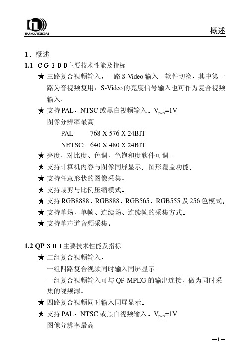
CG300图像采集卡使用说明
概述1主要技术性能及指标һ·S-Video输入其中第一路为音视频复用NTSC或黑白视频输入 768 X 576 X 24BIT NETSC: 640 X 480 X 24BIT 对比度色饱和度软件可调 支持计算机内容与图像同屏显示RGB888RGB555及256色模式 支持单场连续场1.2 QP 二组复合视频输入一组复合视频输入可与QP-MPEG的输出连接NTSC或黑白视频输入概述PAL 亮度色调ͼÐθ²¸Ç¹¦ÄÜ 支持任意形状的图像采集 支持裁剪与比例压缩模式 支持RGB8888RGB565µ¥Ö¡Á¬ÐøÖ¡µÄ²É¼¯·½Ê½ 支持四路单声道音频采集两路PAL/NTSC复合视频两路LINE拾音器输入由两个DH-CG300单路模块组成输入信号相当于DH-CG300的视频输入源路2视频压缩部分具有DH-MPEG-V 的所有图像采集压缩功能相关性能及软件编程请参阅DH-MPEG/QPMPEG使用说明书概述1.4 基本结构及工作原理工作原理框图A/D解码将数据送到数据缓冲器比例压缩及数据格式转换后数据目标位置由软件确定也可以是计算机内存由RISC控制将数据传到指定的内存位置DH-CGMPEG原理框图概述1.5 数据格式RGB32 (RGB 8:8:8:8)Pixel Data[31:0]DWORD Byte 3[31:24]Byte 2[23:16]Byte 1[15:8]Byte 0[7:0]Dw0 Alpha R G BRGB24 (RGB 8:8:8)Pixel Data[31:0]DWORD Byte 3[31:24]Byte 2[23:16]Byte 1[15:8]Byte 0[7:0]Dw0 B1 R0 G0 B0 Dw1 G2 B2 R1 G1 Dw2 R3 G3 B3 R2RGB16 (RGB 5:6:5)Pixel Data[31:0]DWORD Byte 3[31:24]Byte 2[23:16]Byte 1[15:8]Byte 0[7:0]Dw0 {R1[31:27],G1[26:21],B1[20:16]}{R0[15:11],G0[10:5],B0[4:0]}概述RGB15 (RGB 5:5:5)Pixel Data[31:0]DWORD Byte 3[31:24]Byte 2[23:16]Byte 1[15:8]Byte 0[7:0]Dw0{0,R1[30:26],G1[25:21],B1[20:16]}{0,R0[14:10],G0[9:5],B0[4:0]} YUY2-YCrCb 4:2:2Pixel Data[31:0]DWORD Byte 3[31:24]Byte 2[23:16]Byte 1[15:8]Byte 0[7:0]Dw0 Cr0 Y1 Cb0 Y0 Dw1 Cr2 Y3 Cb2 Y2BtYUV-YCrCb 4:1:1Pixel Data[31:0]DWORD Byte 3[31:24]Byte 2[23:16]Byte 1[15:8]Byte 0[7:0]Dw0 Y1 Cr0 Y0 Cb0 Dw1 Y3 Cr4 Y2 Cb4 Dw2 Y7 Y6 Y5 Y4Y8 (8-bit Packed Gray Scale)概述Pixel Data[31:0]DWORD Byte 3[31:24]Byte 2[23:16]Byte 1[15:8]Byte 0[7:0]Dw0 Y3 Y2 Y1 Y0 说明安装2 安装2.1 图像卡硬件安装打开计算机的机箱盖用螺钉将档片固定在机箱上接好视频源输出接口2.2.1 DH-CG300图一 DH-CG300输入输出示意图外部接口:J6复合视频输入2J8S-VIDEO输入或复合视频输入4安装J9缺省是连接S-VIDEO输入需要一根扩展连线S-VIDEO输入端亮度信号 色度信号2.2.2 DH-QP300图二 DH-QP300输入输出示意图外部接口J1J2安装J3J4第二组视频输入第一个CG300模块的复合视频输入1第二个CG300模块的复合视频输入1第三个CG300模块的复合视频输入1第四个CG300模块的复合视频输入1第二组四个复合视频输入1为高阻输入对应两路单声道音频输入第三个与第四个CG300模块的音频输入J7音频插头示意图如下安装2.2.3 DH-CGMPEG输入到第一个 CG300模块输入到第二个 CG300模块接地安装安装图三将图像卡插入计算机PCI扩展槽中找到新硬件并提示要求安装设备的驱动程序下一步在指定位置中搜索驱动程序并指定随卡提供的磁盘或光盘中目录然后Windows应能够自动找到相应的驱动程序配置文件并安装用户还需要安装驱动程序Cg300Qp300\Win9x\Driver.Ins\SetupEx.exe²¢ÖØÐÂÆô¶¯¼ÆËã»úÓû§»¹¿É°²×°Ê¾Àý³ÌÐòCg300Qp300\Win9x\Demo.Ins\SetupEx.exeCg300Qp300\安装Cg300说明书.Doc; CG300用户开发文档\Win9x\dhcapta.inf ; CG300音频驱动程序配置文件dhcaptv.inf ; CG300视频驱动程序配置文件\Driver.Ins\SetupEx.exe ; 驱动安装程序\Demo.Ins\SetupEx.exe ; 示例安装程序设置显示模式显示格式依赖于主机显示卡的显示模式即8位32768色对应图像卡图像格式的RGB55565535色对应图像卡图像格式的RGB56516mil色对应图像卡图像格式的RGB888相关函数参见CG300SetColorSpace¾Í¿ÉÔËÐÐCg300DemoÔËÐпØÖÆÃæ°åÖеÄÉêÇë1024页(4兆)大小的内存如果只向屏幕采集图像而不向内存采集图像安装2.4 附件输入线DH-CG300 FOR WIN9x驱动安装盘一册以光盘中的电子文档为准安装2.5 常见问题的处理由于PCI总线目前还不十分规范我们在总结了前一阶段的使用情况后2.5.1关于显示卡目前已使用正常的显示卡9685 S3 Trio64S3 Trio64V2/DXS3 VIGER/DX S3 83C765,S3 87C375ET4000-W32 S3 Trio64V+S3 TrioV3/DX S3 S600/DXASUS V264SIS 6326/AGP TNT,TNT2,MGA100,MGA200,MGA400等必须是586 并且有PCI扩展槽CPU主频由用户根据任务需要而定演示程序使用说明3 演示程序使用说明3.1 WINDOWS环境下演示程序1. 申请主机内存,参照38页设置图像卡显示模式设置显示模式3. 进入DH-CG300菜单按菜单提示运行演示程序当Windows的显示模式为800ͼÏñ´°¿Ú²»Äܳ¬¹ý768PAL640NTSC软件编程说明4 WINDOWS 环境下软件编程说明在Microsoft Windows9x/ME环境中使用动态连接库G300D32.DLL控制图像卡的工作MS-VB或Borland C/C++C++ Builder等32位语言编程工具的程序中调用函数使用过程中对于使用C/C++编程工具供应用程序在链接(Link)时使用包含在CG300-32.H头文件中DH-QP300是四路同时输入它实际上是将四个CG300集成在一块卡上对于开发人员来说编写的代码也是一样的只要顺序调用我们dll库中的BeginCG3002BeginCG3004ÒÔºóͨ¹ýÕâËĸöÉ豸¾ä±úÀ´Çø·ÖÒ»¿éQP300中不同的CG300模块设备详细的说明请参阅库函数调用接口说明软件编程说明4.1库函数调用接口说明BeginCG300原型说明获取该图像卡的设备句柄凡是对图像卡的操作都要求使用该句柄以获得图像卡句柄int iImageDevice返回值返回图像卡句柄HCG300123½¨Òé关闭其它应用程序来释放更多的内存 或者重新安装驱动程序以便对驱动程序注册图像卡初始化错误1. 如果系统中安装了两块或两块以上的CG300HCG300 hCadr1 = BeginCG300(1); //打开图像卡1HCG300 hCadr2 = BeginCG300(2); //打开图像卡2……… ………… //类推…软件编程说明2. 如果正在使用QP300开发HCG300 hCadr1 = BeginCG300(1); //打开第一个CG300HCG300 hCadr2 = BeginCG300(2); //打开第二个CG300HCG300 hCadr3 = BeginCG300(3); //打开第三个CG300HCG300 hCadr4 = BeginCG300(4); //打开第四个CG3002. 函数int __stdcall EndCG300(HCG300 hcg300)释放图像卡句柄在对图像卡的操作完成之后以释放图像卡句柄和内存HCG300 hcg300调用成功返回1示例CG300Capture原型BOOL Enable)图像卡采集图像控制HCG300 hcg300ENABLE 采集DISABLE 冻结返回值返回1示例CG300Snap原型抓取一帧图像待采完一帧完整图像后即关闭参数图像卡句柄返回值否则返回零CG300Snap(hCadr1);5. 函数int __stdcall CG300SetInpVideoWindow(HCG300 hcg300int Top int Height)设置视频采集输入窗口不是在显示卡上图像显示的窗口视频窗口最大是0576 对于NTSC制0640参数图像卡句柄int Left ÊýֵӦΪ4的倍数int Top ÊýֵӦΪ2的倍数窗口宽度int Height ÊýֵӦΪ2的倍数调用成功返回1示例CG300SetDispWindow原型int Leftint Width 说明图像卡支持图像显示的裁剪功能和按比例压缩功能显示窗口只能等于或小于视频窗口显示窗口中的图像为全部视频输入图像的一个局部或全部当显示窗口小于视频窗口时即为按比例压缩方式参数图像卡句柄int Left ÊýֵӦΪ4的倍数窗口顶部坐标int Width ÊýֵӦΪ4的倍数窗口高度注意:参数Top是屏幕坐标如果采集图像到内存Left=0, Top=0调用成功返回1示例ReadDispWindow原型int Leftint WidthBYTE *lpDestBuf)读取窗口内图像数据存于lpDestBuf中按先行后列的顺序存放每个像素对应其灰度值每个像素有红蓝三个各8位相关函数参见有关图像数据读写的进一步信息及相关函数的使用可参见 Windows 应用程序接口 (API) 中的函数GetPixel以及SetPixelHDC hdc窗口左部坐标int Top窗口宽度int HeightBYTE *lpDestBuf ÓÉÓû§申请和释放Left返回值否则返回零ReadDispWindow(hCard1,144,200,512,512,pBuf);8CG300SetVideoStandard原型设置图像卡视频信号制式在设置制式的同时相关说明及函数参见G300SetInpVideo WindowHCG300 hcg300PAL PAL 制NTSC NTSC制返回值否则返回零。
DTC300中文操作说明
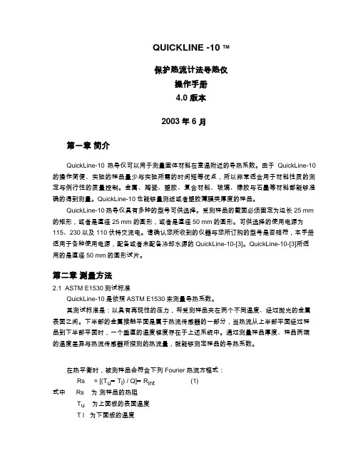
QUICKLINE -10 TM保护热流计法导热仪操作手册4.0 版本2003年6月第一章简介QuickLine-10热导仪可以用于测量固体材料在室温附近的导热系数。
由于QuickLine-10的操作简便、实验的样品量少与实验所需的时间短等优点,所以非常适合用于材料性质的测定与例行性的质量控制。
金属、陶瓷、塑胶、复合材料、玻璃、橡胶与石墨等材料都能够准确的得到测量。
QuickLine-10也能够量测纸或者塑胶薄膜类厚度的样品。
QuickLine-10热导仪具有多种的型号可供选择。
受测样品的截面必须固定为边长25 mm 的矩形,或者是直径25 mm的圆形,或者是直径50 mm的圆形。
可供选择的使用电源为115、230以及110伏特交流电。
请确认您所收到的仪器与您所订购的型号是否相符,本手册适用于各种使用电源,配备或者未配备冷却水源的QuickLine-10-[3]。
QuickLine-10-[3]所适用的是直径50 mm的圆形试片。
第二章测量方法2.1 ASTM E1530测试标准QuickLine-10是依照ASTM E1530来测量导热系数。
其测试标准是:以具有再现性的压力,将受测样品夹在两个不同温度、经过抛光的金属表面之间。
下半部的金属接触平面是属于热流传感器的一部分,当热流从上半部平面经过样品到下半部平面时,一个垂直的温度梯度存在于上述系统中。
通过测量样品厚度、样品两端的温度差异与热流传感器所探测的热流量,就能够测定样品的导热系数。
在热平衡时,被测样品会符合下列Fourier热流方程式:Rs = [(T u━T l) / Q]━R int (1)式中 Rs 为测样品的热阻T u为上面板的表面温度T l 为下面板的温度Q 为通过样品的热流量R int 为样品与上下面板表面的总的接触热阻受测样品的热阻值定义如下:Rs = d /λ (2)where d = sample thicknessλ = thermal conductivity方程式(1)是包括界面间的热阻值,因为QuickLine-10并不是直接量测受测样品本身的实际温差,而是量测和样品接触的上下金属表面间的温差。
肿瘤药敏检测技术

基因检测指导靶向用药结 果不理想下可作为备选方 案
日本进入医保 中国临床应用较多
用药指南未规定 临床应用较少
国外伴随诊断市场 快速增长;进入用 药指南和医保
用药指南未规定
2
一、药敏检测技术需求分析
➢ 临床需求——精准医疗下肿瘤用药指导:药物敏感性、耐药性、副作用等
13
二、药敏检测技术路线
• 2D细胞模型——ATP-TCA生物荧光药敏检测
荧光素酶改造 • 改造目标:提高灵敏度、稳定性 • 改造流程可如下所示:
合成北美萤火虫 荧光素酶基因
设计点突变引物,定 向突变荧光酶潜在的 多个活性相关位点
通过蛋白工作站,纯 化生产重组荧光酶
筛选得到灵敏度和 稳定性高的克隆
四唑蓝比色法 (MTT)
简便、快捷、费用低
敏感性较差,最低仅能检测500个细胞;量程 较小,有效量程在2.0以内。
ATP生物荧光法
敏感性好(可检测最少10个细 胞)、可评价率高、快速检测、
精密度好、具备产业化条件
——
野生型荧光素酶通常稳定性较低,如在体外 37℃放置3分钟即失活。
海创生物的ATP-TCA技术核心: 1、化学结构改良的ATP荧光素酶,稳定表达荧光强度 2、肿瘤选择性培养基
微镜对胶滴中细胞的染色情况进行扫描 ,通过图像软件设定
亮度阈值,排除染色较浅的成纤维细胞, 计算肿瘤细胞形成
清除血细胞、死细胞、 的克隆的OD值, 计算出药物的抑制率。
非细胞杂质
实例2:使用达瑞生物的DR6690进行图像采集和分析
收集活细胞重新分散后与胶原 凝胶混合,制成胶滴
胶滴培养一定时间
胶原可外购,如 Sigma、Fluka的I型胶 原蛋白
双目视觉传感器系统

双目视觉传感器系统视觉检测广泛地应用于工件的完整性、表面平整度的测量:微电子器件(IC芯片、PC板、BGA)等的自动检测;软质、易脆零部件的检测;各种模具三维形状的检测;机器人的视觉导引等。
最具有吸引力的是由视觉传感器阵列组成的大型物体(如白车身)空间三维尺寸多传感器视觉检测系统。
双目视觉传感器由两台性能相同的面阵CCD摄像机组成,基于立体视差的原理,可完成视场内的所有特征点的三维测量,尤其是其它类型的视觉传感器所不能完成的测量任务,如圆孔的中心、三棱顶点位置的测量等。
因此,双目视觉传感器是多传感器视觉检测系统的主要传感器之一。
要实现双目视觉传感器直接测量大型物体关键点的三维测量,就必须知道传感器的内部参数(摄像机的参数)、结构参数(两摄像机间的位置关系)及传感器坐标系与检测系统的整体坐标系的关系(即全局标定)。
因此,在实际测量之前,先要对摄像机进行参数标定。
一般方法是,传感器被提供给整个系统使用前,就离线完成传感器的内部参数及结构参数的标定,采用一标准二维精密靶标及一维精密导轨,通过移动导轨来确定坐标系的一个坐标,通过摄像机的像面坐标及三个世界坐标的对应关系求得这些参数。
这种方法的缺点是:标定过程中,需要精确调整靶标与导轨的垂直关系,而且需多次准确移动导轨;同时标定过程的环境与实际测量的情形有差异;传感器在安装的过程中,易引起部分参数的变化,需多次的拆卸;摄像机还需进行全局标定。
由此可知标定的劳动强度大,精度难以保证。
本文提出了一种现场双目传感器的标定方法,只需先确定摄像机的部分不易变化的参数,其它参数在摄像机安装到整个系统后进行标定。
该方法大大地减少了上述因素的影响,能得到满意的标定精度。
双目视觉测量探头由2个CCD摄像机和1个半导体激光器组成,如下图所示。
半导体激光器作为光源,它发射出一点光源射到一柱状透镜上后变成一条直线。
该线激光投射到工件表面,作为测量标志线。
激光波长为650 nm,其扫描激光线宽约为1mm。
阿托纳UHD-HDVS-300系列产品说明书
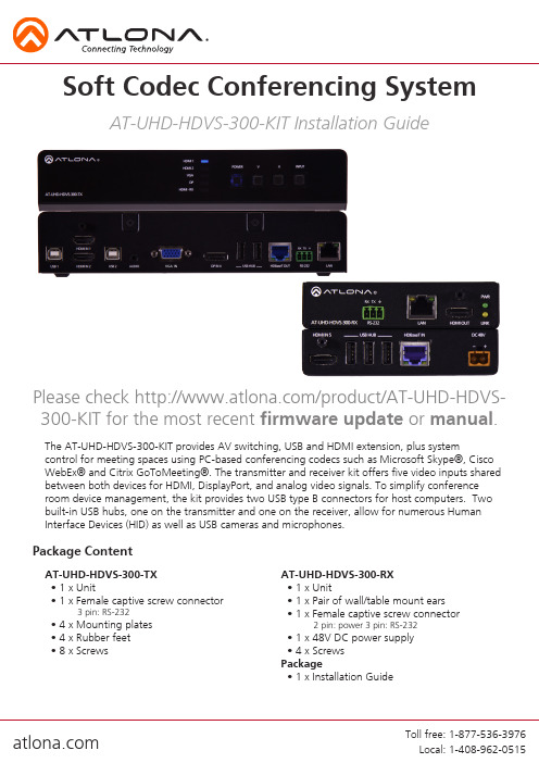
The AT-UHD-HDVS-300-KIT provides AV switching, USB and HDMI extension, plus systemcontrol for meeting spaces using PC-based conferencing codecs such as Microsoft Skype®, Cisco WebEx® and Citrix GoToMeeting®. The transmitter and receiver kit offers five video inputs shared between both devices for HDMI, DisplayPort, and analog video signals. To simplify conference room device management, the kit provides two USB type B connectors for host computers. Two built-in USB hubs, one on the transmitter and one on the receiver, allow for numerous Human Interface Devices (HID) as well as USB cameras and microphones.AT-UHD-HDVS-300-TX • 1 x Unit• 1 x Female captive screw connector3 pin: RS-232• 4 x Mounting plates • 4 x Rubber feet • 8 x ScrewsAT-UHD-HDVS-300-RX • 1 x Unit• 1 x Pair of wall/table mount ears • 1 x Female captive screw connector2 pin: power3 pin: RS-232• 1 x 48V DC power supply • 4 x Screws Package• 1 x Installation GuidePackage ContentSoft Codec Conferencing SystemAT-UHD-HDVS-300-KIT Installation GuidePlease check /product/AT-UHD-HDVS-300-KIT for the most recent firmware update or manual.Back Panel1. RS-232 port - Connect to a control system or display for pass through RS-232 control2. LAN port - Connect network switch, router, or source to this port for pass through Ethernet, TCP/IP, or AMS control3. HDMI OUT - Connect to a display4. LEDs: PWR - Illuminates when the power supply is connected and sending power Link - Illuminates when receiving signal over HDBaseT5. HDMI IN - Connect local HDMI source6. USB Hub - Connect USB source devices here (e.g. webcam, smartboard, etc)7. HDBaseT IN - Connect to a compatible HDBaseT transmitter (e.g. AT-UHD-HDVS-300-TX)8. DC 48V - Connect included 48V power supplyPanel DescriptionsFront Panel1. Input LEDs - LED will illuminate to display the currently selected input2. Power button - Turns switcher on, places the unit in standby mode, or controls a connected display through the HDBaseT output3. ^ ^ buttons - Controls the volume of the display connected to the HDBaseT output4. Input button - Use to switch between inputs5. USB hosts - Connect to a computer using a USB B to USB A cable6. HDMI IN - Connect HDMI sources to these ports7. Audio IN - Connect analog audio here8. VGA IN - Connect VGA source to this port9. DP IN - Connect DisplayPort source to this port10. USB Hub - Connect USB source signal devices (e.g. mouse, keyboard, etc)11. HDBaseT OUT - Connect to an HDBaseT PoE receiver (e.g. AT-UHD-HDVS-300-KIT)12. RS-232 port - Connect to a control system or source for pass through RS-232 control13. LAN port - Connect network switch, router, or source to this port for pass through Ethernet, TCP/IP, or AMS controlTo affix the mounting plates to the unit, use the 8 screws included in the kit to connect them to the bottom of the UHD-HDVS-300-TX. Once the plates are attached, turn the unit over and mount the unit to any surface using the oval holes in all four plates.To affix the mounting brackets to the unit, use the four included screws as well as the four side case screws. The bracket can be affixed with the oval holes pointing to the bottom (for against the wall - picture A) or the oval holes facing the top (for under tables - picture B).Larger ovalhole will beattached toMountingEthernetFor convenience, the UHD-HDVS-300 comes with DHCP on. This enables the switcher to be connected to a network without knowing available IP addresses. If your network does not allow dynamic IP addresses or if you are using the switcher with a TCP/IP control system, this feature may be turned off and the IP address set using front panel.Captive ScrewThe captive screw connectors allow you to cut cables to a suitable length, reducing cable clutter while providing a more reliable connection.ConnectingThe captive screw connectors havea contact bar that is adjusted tocompress the wire against the top contact plate. Use the screws at the top of the connector to compress the wire against the contact plate.When connecting the cables to the female captive screw connector it is important that the wires be terminated correctly. The female captive screw connector has a contact plate at the top and must have the wires touching it for signal to pass. When wired correctly (see picture A) the signal will pass, incorrectly (see picture B) no signal will pass.Female captive screw connectors are included: Power (see picture 1), RS-232 (see picture 2).The power cable (picture 3) will have exposed wires. Each wire is encased in a different colored cover.1PowerRS-232ClockwiseCounter ClockwiseTurn the screws clockwise toraise the contact bar to theupper contact plate and hold the wires in place.Turn the screws counter clockwise to lower the contact bar to release the wires.2RS-232 pin out will be determined by the RS-232 cable and will connect as Rx(receiver), Tx (transmitter), and (ground). (See picture 4)Typical pin out:2 - TX - Transmitter3 - RX - Receiver 5 - GND - GroundPin out color will differ per RS-232 cable.Black : - White : +- +34543298761Category Cable and ConnectorFor the category cables used in the installation of these products, please be sure to use a 568B termination as pictured below:Connector type and size is very important to ensure extenders work correctly. Please use the matching cable type with the correct RJ45 connector. (e.g. CAT 7 cable should use a CAT 7 connector)Important! 4K (UHD) signals are sensitive to cable quality and installation technique. It is recommended to use CAT6a/7 solid core cables for best results.Note: Press and hold the input button on the front panel to switch between static and DHCP IP address. Two button flashes means the unit is in static mode and four button flashes means the unit is DHCP. Static IP configuration will be: 192.168.1.254 - 255.255.255.0Connection Diagram1. My computer is not detecting the connected USB devicesUSB 1 is the default host port. Use AMS to switch between USB hosts2. My display is not turning on/off when using CECNot all displays support CEC, please verify your display has CEC support3. My HDVS-300 is not switching when I connect a new sourceBy default, auto switching is set to off. It can be turned on in AMS4. My unit is not showing up on my networkPress and hold the input button on the front panel to switch between static and DHCP IPaddress. Two button flashes means the unit is in static mode and four button flashes means the unit is DHCP. Static IP configuration will be: 192.168.1.254 - 255.255.255.0。
AIG-300系列硬件用户手册说明书

AIG-300 Series Hardware User’s ManualVersion 1.0, September 2021/product© 2021 Moxa Inc. All rights reserved.AIG-300 Series Hardware User’s Manual The software described in this manual is furnished under a license agreement and may be used only in accordancewith the terms of that agreement.Copyright Notice© 2021 Moxa Inc. All rights reserved.TrademarksThe MOXA logo is a registered trademark of Moxa Inc.All other trademarks or registered marks in this manual belong to their respective manufacturers.DisclaimerInformation in this document is subject to change without notice and does not represent a commitment on the part of Moxa.Moxa provides this document as is, without warranty of any kind, either expressed or implied, including, but not limited to, its particular purpose. Moxa reserves the right to make improvements and/or changes to this manual, or to the products and/or the programs described in this manual, at any time.Information provided in this manual is intended to be accurate and reliable. However, Moxa assumes no responsibility for its use, or for any infringements on the rights of third parties that may result from its use.This product might include unintentional technical or typographical errors. Changes are periodically made to the information herein to correct such errors, and these changes are incorporated into new editions of the publication.Technical Support Contact Information/supportMoxa AmericasToll-free: 1-888-669-2872 Tel: +1-714-528-6777 Fax: +1-714-528-6778Moxa China (Shanghai office) Toll-free: 800-820-5036Tel: +86-21-5258-9955 Fax: +86-21-5258-5505Moxa EuropeTel: +49-89-3 70 03 99-0 Fax: +49-89-3 70 03 99-99Moxa Asia-PacificTel: +886-2-8919-1230 Fax: +886-2-8919-1231Moxa IndiaTel: +91-80-4172-9088 Fax: +91-80-4132-1045Table of Contents1.Introduction ...................................................................................................................................... 1-1Model Descriptions .............................................................................................................................. 1-2 Package Checklist ............................................................................................................................... 1-2 Product Features ................................................................................................................................ 1-3 Product Specifications ......................................................................................................................... 1-3 2.Hardware Introduction...................................................................................................................... 2-1Appearance ........................................................................................................................................ 2-2 AIG-301-AZU-LX ......................................................................................................................... 2-2AIG-301 US, EU, AP, and CN Models .............................................................................................. 2-3 Dimensions ........................................................................................................................................ 2-4 AIG-301-AZU-LX ......................................................................................................................... 2-4AIG-301 US, EU, AP, and CN Models .............................................................................................. 2-4 LED Indicators .................................................................................................................................... 2-5 Reboot .............................................................................................................................................. 2-5 Reset to Default ................................................................................................................................. 2-5 Real-time Clock .................................................................................................................................. 2-5 Installation Options ............................................................................................................................. 2-6 DIN-rail Mounting ........................................................................................................................ 2-6Wall Mounting (optional) .............................................................................................................. 2-6 3.Hardware Connection Description ..................................................................................................... 3-1Wiring Requirements ........................................................................................................................... 3-2 Connecting the Power .................................................................................................................. 3-2Grounding the Unit ...................................................................................................................... 3-3 Connecting to the Network ................................................................................................................... 3-3 Connecting to a USB Device ................................................................................................................. 3-3 Connecting to Serial Ports .................................................................................................................... 3-3 Inserting the microSD Card .................................................................................................................. 3-4 Connecting to the Console Port ............................................................................................................. 3-4 Connecting the CAN Port ..................................................................................................................... 3-4 Connecting the Digital Inputs and Digital Outputs ................................................................................... 3-5 Inserting the SIM Card ........................................................................................................................ 3-5 Installing the Wi-Fi Module (US, EU, AP, and CN models only) .................................................................. 3-5 Connecting the Antennas ..................................................................................................................... 3-9 A.Regulatory Approval Statements ....................................................................................................... A-11Introduction The AIG-300 Series advanced IIoT gateways are designed for Industrial IoT applications, especially for distributed and unmanned sites in harsh operating environments. ThingsPro Edge and Azure IoT Edge software are preloaded and seamlessly integrated with the AIG-300 Series to enable easy, reliable, yet secure sensor-to-cloud connectivity for data acquisition and device management using the Azure Cloud solution. With the use of the ThingsPro Proxy utility, the device provisioning process is easier than ever. Thanks to the robust OTA function, you never have to worry about system failure during software upgrades. With the secure boot function enabled, you can enable the booting process of AIG-300 Series to prevent malicious software injection.The following topics are covered in this chapter:❒Model Descriptions❒Package Checklist❒Product Features❒Product SpecificationsModel DescriptionsThe AIG-300 Series includes the following models:•AIG-301-T-AZU-LX: Advanced IIoT gateway with Arm® Cortex™-A7 dual-core 1 GHz processor, 1 CAN port, 4 DIs, 4 DOs, ThingsPro Edge and Azure IoT Edge software, -40 to 85°C operating temperature •AIG-301-T-US-AZU-LX: Advanced IIoT gateway with Arm® Cortex™-A7 dual-core 1 GHz processor, 1 CAN port, 4 DIs, 4 DOs, USA LTE band support, ThingsPro Edge and Azure IoT Edge software, -40 to70°C operating temperature•AIG-301-T-EU-AZU-LX: Advanced IIoT gateway with Arm® Cortex™-A7 dual-core 1 GHz processor, 1 CAN port, 4 DIs, 4 DOs, Europe LTE band, ThingsPro Edge and Azure IoT Edge software, -40 to 70°Coperating temperature•AIG-301-T-AP-AZU-LX: Advanced IIoT gateway with Arm® Cortex™-A7 dual-core 1 GHz processor, 1 CAN port, 4 DIs, 4 DOs, Asia Pacific LTE band, ThingsPro Edge and Azure IoT Edge software, -40 to 70°Coperating temperature•AIG-301-T-CN-AZU-LX: Advanced IIoT gateway with Arm® Cortex™-A7 dual-core 1 GHz processor, 1 CAN port, 4 DIs, 4 DOs, ThingsPro Edge and Azure IoT Edge software, -40 to 70°C operatingtemperature•AIG-301-AZU-LX: Advanced IIoT gateway with Arm® Cortex™-A7 dual-core 1 GHz processor, 1 CAN port, 4 DIs, 4 DOs, ThingsPro Edge and Azure IoT Edge software, -20 to 85°C operating temperature •AIG-301-US-AZU-LX: Advanced IIoT gateway with Arm® Cortex™-A7 dual-core 1 GHz processor, 1 CAN port, 4 DIs, 4 DOs, USA LTE band support, ThingsPro Edge and Azure IoT Edge software, -20 to70°C operating temperature•AIG-301-EU-AZU-LX: Advanced IIoT gateway with Arm® Cortex™-A7 dual-core 1 GHz processor, 1 CAN port, 4 DIs, 4 DOs, Europe LTE band, ThingsPro Edge and Azure IoT Edge software, -20 to 70°Coperating temperature•AIG-301-AP-AZU-LX: Advanced IIoT gateway with Arm® Cortex™-A7 dual-core 1 GHz processor, 1 CAN port, 4 DIs, 4 DOs, Asia Pacific LTE band, ThingsPro Edge and Azure IoT Edge software, -20 to 70°Coperating temperature•AIG-301-CN-AZU-LX: Advanced IIoT gateway with Arm® Cortex™-A7 dual-core 1 GHz processor, 1 CAN port, 4 DIs, 4 DOs, ThingsPro Edge and Azure IoT Edge software, -20 to 70°C operatingtemperatureNOTE The CN model does not come with the LTE module preinstalled. We have tested the model with the Quectel EC20 R2.1 LTE module and recommend operating the LTE module in the -20 to 65°C temperature range.Contact Moxa’s distributor in China for more information.Package ChecklistThe package contains the following items:•AIG-300 Series advanced IIoT gateway•Power jack•DIN-rail mounting kit•Quick installation guide (printed)•Warranty cardNOTE Notify your sales representative if any of the above items are missing or damaged.NOTE The console cable is not included in the package; you need to purchase it separately.Product Features•Simplifies data acquisition and device management via the ThingsPro Edge software.•Seamless integration with ThingsPro Edge and Azure IoT Edge enables easy, reliable, yet secure cloud connectivity.•Supports easy device-provisioning with the ThingsPro Proxy utility.•Provides robust OTA function to prevent system failure during software upgrades.•Equipped with secure boot to prevent malicious software-injection attacks.Product SpecificationsNOTE The latest specifications for Moxa's products can be found at https://.2Hardware Introduction The AIG-300 Series devices are compact and rugged, making them suitable for industrial applications. The LED indicators allow you to monitor device performance and quickly identify issues, and the multiple ports can be used to connect a variety of devices. The AIG-300 Series comes with a reliable and stable hardware platform that lets you devote the bulk of your time to application development. In this chapter, we provide basic information about the device’s hardware and its various components.The following topics are covered in this chapter:❒AppearanceA IG-301-AZU-LXA IG-301 US, EU, AP, and CN Models❒DimensionsA IG-301-AZU-LXA IG-301 US, EU, AP, and CN Models❒LED Indicators❒Reboot❒Reset to Default❒Real-time Clock❒Installation OptionsD IN-rail MountingW all Mounting (optional)Appearance AIG-301-AZU-LXTop Panel ViewFront Panel ViewBottom Panel ViewAIG-301 US, EU, AP, and CN ModelsNOTE The CN model does not come with the LTE module preinstalled. Contact Moxa’s distributor in China for more information.Top Panel ViewFront Panel ViewBottom Panel ViewDimensionsAIG-301-AZU-LXAIG-301 US, EU, AP, and CN ModelsLED IndicatorsThe function of each LED is described in the table below: LED Name Status Function PWR1/PWR2 Green Power is on OffNo power SIM Green SIM2 is in use Yellow SIM1 is in useUSR Green/Yellow Green: System is operating normallyYellow: System is initializing and running initial boot-up process L1/L2/L3YellowCellular signal strength L1+L2+L3: Strong L2+L3: Normal L3: WeakW1/W2/W3YellowWLAN signal strength W1+W2+W3: Strong W2+W3: Normal W3: WeakLAN1/LAN 2 (RJ45 connector)GreenSteady on 100 Mbps Ethernet linkBlinking Data is being transmitted or received Yellow Steady on 1000 Mbps Ethernet linkBlinkingData is being transmitted or receivedOff No Ethernet connection or 10 Mbps Ethernet linkRebootTo reboot the device, press the function (FN) button for 1 second.Reset to DefaultPress and hold the function (FN) button between 7 to 9 seconds to reset the device to the factory default settings. When the reset button is held down, the USR LED will blink once every second and become steady after 7 to 9 seconds. Release the button within this period to load the factory default settings.Real-time ClockThe real-time clock is powered by a non-chargeable battery. We strongly recommend that you do not replace the lithium battery without help from a qualified Moxa support engineer. If you need to change the battery, contact the Moxa RMA service team.Installation OptionsDIN-rail MountingThe aluminum DIN-rail attachment plate is already attached to the product’s casing. To mount the device on to a DIN rail, make sure that the stiff metal spring is facing upwards and follow these steps.1.Pull down the bottom slider of the DIN-rail bracket located at theback of the unit2.Insert the top of the DIN rail into the slot just below the upperhook of the DIN-rail bracket.tch the unit firmly on to the DIN rail as shown in theillustrations below.4.Push the slider back into place.Wall Mounting (optional)The device can be mounted on to a wall using a wall-mounting kit as shown in the following illustrations.The optional wall-mounting kit is not included in the product package and should be purchased separately.Follow these steps to mount the device on to a wall:Step 1Use four screws to fasten the wall-mounting brackets on the left panel of the device.Step 2Use another four screws to mount the device on a wall or a cabinet.NOTE •Test the screw head and shank size by inserting the screws into one of the keyhole shaped apertures of the wall-mounting plates before attaching the plate to the wall.•Do not drive the screws in all the way—leave a space of about 2 mm to allow room for sliding the wall mount panel between the wall and the screws.3 Hardware Connection DescriptionIn this chapter, we describe how to connect the AIG-300 to a network and other devices.The following topics are covered in this chapter:❒Wiring RequirementsC onnecting the PowerG rounding the Unit❒Connecting to the Network❒Connecting to a USB Device❒Connecting to Serial Ports❒Inserting the microSD Card❒Connecting to the Console Port❒Connecting the CAN Port❒Connecting the Digital Inputs and Digital Outputs❒Inserting the SIM Card❒Installing the Wi-Fi Module (US, EU, AP, and CN models only)❒Connecting the AntennasWiring RequirementsIn this section, we describe how to connect various devices to the AIG-300. Be sure to read and follow these common safety precautions before proceeding with the installation of any electronic device:• Use separate paths to route wiring for power and devices. If power wiring and device wiring paths mustcross, make sure the wires are perpendicular at the intersection point.NOTEDo not run signal or communication wiring and power wiring in the same wire conduit. To avoid interference, wires with different signal characteristics should be routed separately.• You can use the type of signal transmitted through a wire to determine which wires should be keptseparate. The rule of thumb is that wiring that shares similar electrical characteristics can be bundled together.• Keep input wiring and output wiring separate.• When necessary, it is strongly advised that you label wiring to all devices in the system.Connecting the PowerConnect the power jack (in the package) to the DC terminal block (located on the top panel), and then connect the power adapter. It takes about 3 minutesfor the system to boot up. Once the system is ready, the power LEDs will light up. Both models support dual power inputs for redundancy.Grounding the UnitThere is a grounding connector on the top panel of the device. Use this connector to connect a well-grounded mounting surface, such as a metal panel. Grounding and wire routing help limit the effects of noise due to electromagnetic interference (EMI).Connecting to the NetworkThe Ethernet ports are located on the front panel of the device. The pin assignments for the Ethernet ports are shown in the following figure. If you are using your own cable, make sure that the pin assignments on the Ethernet cable connector match the pin assignments on the Ethernet port.Pin 10/100 Mbps1000 Mbps 1 Tx+ TRD(0)+ 2 Tx- TRD(0)- 3Rx+ TRD(1)+ 4 – TRD(2)+ 5 – TRD(2)- 6 Rx- TRD(1)- 7 – TRD(3)+ 8–TRD(3)-Connecting to a USB DeviceThe device comes with a USB port located on the lower part of the front panel, allowing users to connect to a device with an USB interface. The USB port uses a type-A connector.Connecting to Serial PortsThe serial ports can be configured by software for RS-232, RS-422, or RS-485. The pin assignments for the ports are shown in the following table:PinRS-232RS-422/RS-485 4wRS-485 2w1 – TxD-(A) –2 RxD TxD+(B) –3 TxD RxD+(B) Data+(B)4 DTR RxD-(A) Data-(A)5 GND GND GND6 DSR – –7 RTS – – 8CTS––Inserting the microSD CardThe device comes with a microSD socket for storage expansion. The microSD socket is located on the lower part of the front panel. To install the card, remove the screw and the protection cover to access the socket, and then insert the microSD card into the socket directly. You will hear a click when the card is in place. To remove the card, push the card in before releasing it.Connecting to the Console PortThe console port is an RS-232 port located on the top panel and can be connected to a 4-pin pin header cable. You can use this port for debugging or firmware upgrade.Pin Signal 1 TxD 2 RxD 3NC 4GNDConnecting the CAN PortThere is a CAN port in DB9 interface, located on the bottom panel. Refer to the figure on the left for detailed pin definitions.PinDefinition1 –2 CAN_L 3CAN_GND4 –5 (CAN_SHLD)6 (GND)7 CAN_H8 – 9(CAN_V+)Connecting the Digital Inputs and Digital OutputsThere are four digital inputs and four digital outputs on the top panel. Refer to the figure on the left for detailed pin definitions.Inserting the SIM CardThe device comes with a SIM card socket that allows users to install two SIM cards for cellular communication. Step 1Remove the screw on the SIM card holder cover located on the bottom panel of the device.Step 2Insert the SIM card into the socket.Make sure you insert in the right direction. To remove the SIM card, press the SIM card in to release and then you can pull out the SIM card.Installing the Wi-Fi Module (US, EU, AP, and CN models only)The optional Wi-Fi wireless module is not included in the product package and should be purchased separately. The Wi-Fi wireless module package contains the following items: • 1 x Wi-Fi module• 1 x thermal pad (25 x 10 x 1 mm) • 2 x black screws (M2.5 x 4 mm)• 2 x bronze spacers (M/F M3 x 4/M3 x 5 mm) • 1 x insulation pad • 1 x heatsinkNOTENotify your sales representative if any of the above items are missing or damaged.Follow these steps to install the Wi-Fi module for the device.1.Loosen the four screws on the right panel of your computer.2.Remove the right-side cover to expose the Mini-PCIe socket.The Wi-Fi socket is located beside the cellular module socket.3.Remove the plastic sheet on the thermal pad and stick the thermal pad on the metal surface asindicated.4.Insert the wireless module card into the socket at an angle.5.Push down the wireless module card and secure it by fastening the two black screws (M2.5x4 mm).6.Remove the plastic protection covers on the antenna connectors.7.Connect the #W1 SMA cable to the Main connector and the #W2 SMA cable to the Aux connector on thewireless module card installed.8.Stick the insulation tape on the connectors.9.Remove the two silver screws (M3x6 mm) and keep them for later use.10.Fasten the two bronze screws on to the screws on the board.11. Remove the plastic sheet on the thermal pad of the heat sink, install the heat sink pad on the module,and secure the heat sink with the two silver screws (M3 x 6 mm).12. Put back the right cover of the computer and secure it with screws.Connecting the AntennasThere are two cellular antenna connectors (C1 and C2) on the front panel ofthe device. In addition, a GPS connector is provided for the GPS module. Allthree connectors are of SMA type. Connect the antennas to these connectorsas shown below.There are two Wi-Fi antenna connectors (W1 and W2) on the top panel ofthe device. Connect the antennas on the connectors as shown below. BothW1 and W2 connectors are of RP-SMA type.A Regulatory Approval StatementsThis device complies with part 15 of the FCC Rules. Operation is subject to the followingtwo conditions: (1) This device may not cause harmful interference, and (2) this devicemust accept any interference received, including interference that may cause undesiredoperation.Class A: FCC Warning! This equipment has been tested and found to comply with the limits for a Class A digital device, pursuant to part 15 of the FCC Rules. These limits are designed to provide reasonableprotection against harmful interference when the equipment is operated in a commercial environment. This equipment generates, uses, and can radiate radio frequency energy and, if not installed and used in accordance with the instruction manual, may cause harmful interference to radio communications.Operation of this equipment in a residential area is likely to cause harmful interference in which case the users will be required to correct the interference at their own expense.European Community。
- 1、下载文档前请自行甄别文档内容的完整性,平台不提供额外的编辑、内容补充、找答案等附加服务。
- 2、"仅部分预览"的文档,不可在线预览部分如存在完整性等问题,可反馈申请退款(可完整预览的文档不适用该条件!)。
- 3、如文档侵犯您的权益,请联系客服反馈,我们会尽快为您处理(人工客服工作时间:9:00-18:30)。
1 . 4 基本结构及工作原理
1 . 4 . 1 D H - C G 3 0 0 / Q P 3 0 0 工作原理框图
Video1 Video2 Video3
多
A/D
格式转换
缓冲
路
P
切
S-Video/
换
Video4
C RISC
I
Audio
A/D
接
缓冲
口
RISC
置
1 . 4 . 2 D H - C G M P E G 工作原理框图
音频 1 视频 1 音频 2
CG300 视频 音频
CG300 视频 音频
MPEG-V
P主Leabharlann C 机I
内
桥
存
视频 2
MPEG-V
3
1 . 5 数据格式
RGB32(RGB8:8:8:8)
1 . 2 D H - Q P 3 0 0 技术性能及指标 二组复合视频输入 一组四路复合视频同时输入 同屏显示 一组复合视频输入可与 QP-MPEG 的输出连接 做为同时采集的 视频源 支持四路单声道音频采集
1
概述 1 . 3 D H - C G M P E G 技术性能及指标
概述
1 概述
1 . 1 D H - C G 3 0 0 技术性能及指标 三路复合视频输入 一路 S-Video 输入 软件切换 其中第一 路为音/视频复用 S-Video 的亮度信号输入也可作为复合视频 输入 支持 PAL NTSC 彩色/黑白视频输入 信号幅度 = 1Vp-p 图像分辨率最高 PAL 制 768 576 24 位 NTSC 制 640 480 24 位 可编程亮度 对比度 色度 色饱和度 支持 YUV422 RGB8888 RGB888 RGB565 RGB555 及 Y8 模式 图像数据数值范围 亮度 0-255 或 16-253 可选 色度 2-253 支持计算机内容与图像同屏显示 图形覆盖功能 支持图像的裁剪与比例压缩模式 支持单场 单帧 连续场 连续帧的采集方式 支持单声道音频采集 支持 Win9x WinNT Win2000 WinXP 等操作系统 支持多种开 发环境
支持热线 010-62625148 010-62625150 010-62625152
前言
首先感谢您选用大恒图像产品 DH-CG300 视频采集卡是我公 司新近开发的彩色/黑白视频图像采集卡 它具有使用灵活 集成 度高 功耗低等特点 由于采用 PCI 总线 所采集的图像数据传输 基本不占用 CPU 时间 并可将图像直接传送到计算机内存或显存 是当今市场上相当流行的一种图像采集卡 它适用于图像处理 工业控制 多媒体监控 办公自动化等领域
目录 2.4.4 WindowsNT 环境下· · · · · · · · · · · · · · · · · · · · · · 22 2.5 升级图像卡设备驱动程序 · · · · · · · · · · · · · · · · · · · 23 2.5.1 Windows9x/2000 环境下 · · · · · · · · · · · · · · · · · · · 23 2.5.2 WindowsXP 环境下 · · · · · · · · · · · · · · · · · · · · · · 28 2.5.3 WindowsNT 环境下· · · · · · · · · · · · · · · · · · · · · · 28 2.6 安装图像卡演示程序· · · · · · · · · · · · · · · · · · · · · · 29 2.7 安装图像卡软件开发包 · · · · · · · · · · · · · · · · · · · · 35 3 使用单卡演示程序 · · · · · · · · · · · · · · · · · · · · · · · · 38 3.1 启动 · · · · · · · · · · · · · · · · · · · · · · · · · · · · · · · 38 3.2 菜单功能 · · · · · · · · · · · · · · · · · · · · · · · · · · · · 38 3.3 图像卡运行 · · · · · · · · · · · · · · · · · · · · · · · · · · · 40 3.3.1 采集图像到屏幕· · · · · · · · · · · · · · · · · · · · · · · · 40 3.3.2 文件和打印操作 · · · · · · · · · · · · · · · · · · · · · · · 42 3.3.3 控制图像卡 · · · · · · · · · · · · · · · · · · · · · · · · · · 42 3.3.4 分配静态内存 · · · · · · · · · · · · · · · · · · · · · · · · · 45 3.3.5 采集图像到内存中 · · · · · · · · · · · · · · · · · · · · · · 46 4 使用多卡演示程序 · · · · · · · · · · · · · · · · · · · · · · · · 49 4.1 启动 · · · · · · · · · · · · · · · · · · · · · · · · · · · · · · · 49 4.2 菜单功能 · · · · · · · · · · · · · · · · · · · · · · · · · · · · 49 4.3 图像卡运行 · · · · · · · · · · · · · · · · · · · · · · · · · · · 51
大恒图像系列板卡
DH-CG300/QP300/CGMPEG 图像采集卡使用说明书
2003 年 6 月版
本手册中所提及的其它软硬件产品的商标与名称 都属于相 应公司所有 本手册的版权属于中国大恒 集团 有限公司北京图像视觉 技术分公司所有 未得到本公司的正式许可 任何组织或个人均 不得以任何手段和形式对本手册内容进行复制或传播 本手册的内容若有任何修改 恕不另行通知
两路 PAL/NTSC 复合视频输入 两路 LINE/拾音器音频输入 视频采集部分由两个 DH-CG300 单路模块组成 具有 DH-CG300 的所有图像采集功能 输入信号相当于 DH-CG300 的视频输入源 路 视频压缩部分由两个 DH-MPEG-V 单路输入模块组成 具有
DH-MPEG-V 的所有图像采集压缩功能 输入信号相当于 DH-MPEG-V 的视频输入 1
© 2003 中国大恒 集团 有限公司北京图像视觉技术分公司 版权所有 网站
销售信箱 sales@ 销售热线 010-62542059 010-62542060 010-62570613 010-62574803 支持信箱 support @
[23:16] [15:8]
DW0
B1
R0
G0
DW1
G2
B2
R1
DW2
R3
G3
B3
概述
Byte 0 [7:0]
B
Byte 0 [7:0]
B0 G1 R2
DWORD DW0
RGB15(RGB5:5:5)
Pixel Data[31:0]
DWORD
Byte 3
Byte 2
Byte 1
[31:24]
[23:16] [15:8]
DW0
Alpha
R
G
RGB24(RGB8:8:8)
Pixel Data[31:0]
DWORD
Byte 3
Byte 2
Byte 1
[31:24]
2
概述
视频图像经多路切换器 解码器 A/D 变换器 将数字化的图
像数据送到数据缓冲器 经裁剪 比例压缩及数据格式转换后 由
内部 RISC 控制图形覆盖与数据传输 数据传输目标位置由软件确
定 可以是显存 也可以是计算机内存
音频信号经 A/D 转换后 由 RISC 控制将数据传到指定内存位
本手册详细介绍了 DH-CG300 的工作原理 软硬件安装 使用 DH-QP300 是在一块单板上集成了四块 DH-CG300 但每一块 DH-CG300 仅支持两路复合视频输入 DH-QP300 特别适于多画面同 时采集 DH-CGMPEG 是在一块板上集成了二块 DH-CG300 和二块 DH-MPEG
目录
目 录
1 概述· · · · · · · · · · · · · · · · · · · · · · · · · · · · · · · · · 1 1.1 DH-CG300 技术性能及指标 · · · · · · · · · · · · · · · · · · · 1 1.2 DH-QP300 技术性能及指标 · · · · · · · · · · · · · · · · · · · 1 1.3 DH-CGMPEG 技术性能及指标 · · · · · · · · · · · · · · · · · · 2 1.4 基本结构及工作原理· · · · · · · · · · · · · · · · · · · · · · · 2 1.4.1 DH-CG300/QP300 工作原理框图 · · · · · · · · · · · · · · · · 2 1.4.2 DH-CGMPEG 工作原理框图 · · · · · · · · · · · · · · · · · · 3 1.5 数据格式 · · · · · · · · · · · · · · · · · · · · · · · · · · · · · 4 2 安装· · · · · · · · · · · · · · · · · · · · · · · · · · · · · · · · · 7 2.1 产品清单 · · · · · · · · · · · · · · · · · · · · · · · · · · · · · 7 2.2 运行环境 · · · · · · · · · · · · · · · · · · · · · · · · · · · · · 7 2.2.1 显示卡 · · · · · · · · · · · · · · · · · · · · · · · · · · · · · 7 2.2.2 主机板 · · · · · · · · · · · · · · · · · · · · · · · · · · · · · 8 2.3 安装图像卡硬件· · · · · · · · · · · · · · · · · · · · · · · · · 10 2.3.1 注意事项 · · · · · · · · · · · · · · · · · · · · · · · · · · · 10 2.3.2 图像卡的输入 输出端口 · · · · · · · · · · · · · · · · · · 10 2.3.3 安装步骤 · · · · · · · · · · · · · · · · · · · · · · · · · · · 13 2.4 安装图像卡设备驱动程序 · · · · · · · · · · · · · · · · · · · 14 2.4.1 文件目录 · · · · · · · · · · · · · · · · · · · · · · · · · · · 14 2.4.2 Windows9x/2000 环境下 · · · · · · · · · · · · · · · · · · · 14 2.4.3 WindowsXP 环境下 · · · · · · · · · · · · · · · · · · · · · · 20