通用低压微波雷达感应模块规格书
新日本电器有限公司微波分支公司的NJR4265R系列K-Band微波智能运动传感器模块说明书
© Copyright 2017New Japan Radio Co., Ltd.Microwave Division-Notice of Proprietary Information-Documents and contents are proprietary to New Japan Radio Co., Ltd. This publication and its contents may not be reproduced or distributed for any other purpose without the written permission of New Japan Radio Co., Ltd.24GHz Microwave Intelligent Motion Sensorfor Short Distance, Low Speed ApplicationsNJR4265R is intelligent motion sensor that is designed for the sensing of short distance low speed movement object of pedestrian etc. The steady sensing of moving object is realized by embedded software. It is suitable for the built-in use of the sensing function to various equipment as all functions are integrated in a small package and it can easily control from PC/MCU by UART interface. Further, stand-alone operation is also possible.Features:●M otion sensor using the 24GHz Microwave Doppler ●Antenna, RF circuit, IF amp, MCU and voltageregulator are integrated in a small package(14 x 20.4 x 8.8mm)●Communication with PC/MCU is available byUART interface and stand-alone operation is also possible●S ignal processing software for the steady sensing Enhancing the signal from movement object and decreasing random noisesDecreasing the mutual interference between sensorsI dentification of direction for movement object(approaching and leaving).●L ow voltage operation and low power consumption ●S leep mode for reducing power when unnecessary Applications:●Various equipment control by human sensing Energy saving managementEntrance and exit managementSafety and SecurityFunctional Brock diagram:Products Line-up:●Model Numbering System●Model Number List*Note: The Model of FCC certification (Model No. NJR4265RF3C1) must refer to Appendix of “FCC Statement of NJR4265RF3”.●Evaluation KitThe evaluation kit is available for NJR4265R series. The contents of the evaluation kit are as follows.Evaluation Kit P/N.: NJR4265J1KContents1.Sensor Module2.Evaluation Board (Functions are UART-to-USB convertor and analog threshold setting)3.GUI SoftwareB Cable1.Absolute Maximum RatingITEM MIN. TYP. MAX. UNITS REMARKS Supply Voltage 0 ― 6.5 VOperating Temperature -40 ―+85 °CStorage Temperature -40 ―+85 °C2.Electrical CharacteristicsPower SupplyOperating Voltage 3.0 3.3/5.0 5.25 VOperating CurrentSensing mode ―60 ―mASleep mode ― 4 ―mASensor RFConformity Standard ●EU Certification: Radio Equipment Directive 2014/53/EU●FCC Certification: Part 15.245●MIC Technical Conformity (Japan): ARIB STD-T73Operating FrequencyF1 type 24.05 ―24.25 GHz EU Certification F2 type 24.15 ―24.25 GHzF3 type 24.075 ―24.175 GHz FCC Certification J1 type 24.05 ―24.25 GHz Japan Certification Frequency Stability (Temp.) ―+/-0.2 ―MHz/°C T a=-20to +60 °C Output Power (E.I.R.P.) 8.2 ―13 dBm2nd Harmonics (E.I.R.P.) ――-30 dBmAntenna-3dB beam width (Horizontal)―70 ―deg.-3dB beam width (Vertical) ―54 ―deg.―――dB No Side lobe Side lobe suppression(Horizontal)Side lobe suppression―――dB No Side lobe (Vertical)Typical Radiation Pattern3.Environmental characteristicsITEM SPECIFICATIONOperation Temperature -20 to +60 °CStorage Temperature -40 to +80 °CHumidity 0 to 95 %@+30 °CVibration 49.03 m/s2(5 G), 30 to 50 Hz, 10 minutes, XYZ direction Shock 196.13 m/s2(20 G), Half sine, 11 ms, XYZ direction, 3 times4. Sensing PerformanceCommon measure condition Ta= +25 °C ITEMPERFORMANCE UNITS REMARKSSpeed Range of T arget0.25 to 1.0m/s Maximum Distance in Front 10 m Detectable Angle+/-35deg.*Note) This is not the specification to guarantee the performance of this product. As for the specification of theproduct, the electric characteristic standard is applied. Sensing performance shown here is an example of the result of being likely to obtain it when this product is used on the following conditions. Actual sensing performance would be greatly different in each environment used.Please do enough confirmation in the environment actually used.Definition of Sensing Performance* Speed Range of T arget: The range of the speed that the detection distance become 70% of the detection distance of 0.5 m/s* Maximum Distance in Front:Detectable distance that can be detected in front of sensor when a threshold value set to [999] or when VDD is added to a threshold setting terminal* Detectable Angle:Angle where detection distance becomes 70% of the frontMeasurement condition of detection performance* Temperature:T a = +25 °C* T arget of Measurement: An adult of 170cm/70kg approaching at the rate of 0.5m/s from the front of sensor* Installation of the Sensor:T he sensor is installed as the antennas horizontal horizontally in a height of 1 m from the ground.Weight 70kgTop ViewSide View5.Signal processing for the steady sensing of moving objectThis product is embedding software for the steady sensing of moving object. It is enhance the signal from movement object of pedestrian etc. and is reduce random noise and sudden signal which caused an incorrect detection by using the signal from IQ mixer, namely Environmental Noise Reduction.The following effects are expectable.●Reduction of false detection by random movement such as the shakes of plant by wind or thenoise of rain etc.●Reduction of the false detection by sudden movement such as the insect etc. which cross justbefore a sensor●Steady detection of movement objects such as pedestrian under the environment where theabove-mentioned noise exists.●Reduction of the mutual interference of sensors●Identification of direction of movement (approach and leaving)*Note) This signal processing function assumes the following noises are reduced, and pedestrian's movement is emphasized. However, it is likely to become a counter productivity for a signal outside assumption.6. Interface6.1. Pin AssignmentPin diagram (Bottom View)# NAMEI/O DESCRIPTION 1Option― Option PinOption pin is not assigned at NJR4265R. Keep it in electrically open state 2 TxD (UART) O UART TxD 3 RxD (UART)I UART RxD4Threshold SettingI Analog threshold voltage (V TH )Available to set by the voltage applied to this pin.Threshold of detection distance = V TH / V DD x 10 m *Note1 5 Detect(approaching) O Output for approaching detection *Note2H: Detect / L: No detect6 Detect (leaving) O Output for leaving detection *Note2H: Detect / L: No detect7 VDD I Power Supply Input (V DD ): 3.0 to 5.25 V 8 ― ― Internal connection *Note3DO NOT connect any signal lines including GND. 9 ― ― 10 ― ― 11 GND―GND Pin*Note1) Detection distance assumes the case that an adult of 170cm/70kg approaches at the rate of 0.5m/sfrom the front.*Note2) Pin 5 or 6 is changed to H level respectively when the movements of approaching or leaving isdetected. (Output current < 5mA)*Note3) Pin 8, 9 and10 are used for internal connection. Those must be electrically open independently. Thesepins must use the via holes of an independent pad when the sensor install on a PCB. Do not connect also between these terminals too.6.2.Asynchronous Serial Data Bus (UART) InterfaceNJR4265R is able to control of sensor mode, set of threshold level, acquisition of detection result and Communication ParametersBaud Rates 9600 bpsData Bits 8 bitsStop Bits 1 bitsParity odd ―Handshake non ―Byte Order LSB ―7. Operational modeMODEDESCRIPTIONPower ON / Reset CPU Reset.Initialization Mode Initialize and wait until sensor is stabilized.Notice command is sent out after the completion of initialization.Detection ModeDetection command is sent when following changes arise in the state of the sensor detection.1. detect approaching object2. detect leaving object3. state change from detection to no-detectionSleep ModeShutdown of all analog circuit for reducing the current.When returning to detection mode, about one second needs for stabilization of the sensor .*Note) When the watch dog timer overflows, it is reset from any mode●The default detection mode at the Power-on or CPU reset is analog threshold mode. It is possible to change to the command threshold mode by sending parameter setting commands. (@SP, @SM and @SC)● The @SA command is effective when changing from the command threshold to an analog threshold mode.●When mode is changed to sleep mode or is resumed from sleep mode, the threshold mode is preserved. Moreover, the change of the threshold mode in sleep mode is also possible.State Transition Diagram State Transition Tablemunication command8.1.OutlineCOMMAND TYPE DIRECTION DESCRIPTION EFFECTIVE MODE Detection Sensor to Host Sending from sensor when movementis detectedDetection modeMode Change Host to Sensor Change the sensor mode Detection modeSleep mode Parameter Setting Host to Sensor Setting and change of thresholdparametersQuery Sensor to HostHost to Sensor Reading of state of sensor (mode , parameters)Reset Host to Sensor Reset of sensorStart Notification Sensor to Host Sending from sensor when initializationis completed InitializationmodeError Response Sensor to Host Sending from sensor when error occurs All modemunication Command ListBoth Sensor-to-Host (S-to-H) and Host-to-sensor (H-to-S) use the following formats.@ XXX xx <CR><LF>@: Command headerXXX: Command characters, alphabet 1-3 characters. (Capital letter and small letter are Distinguished.)xx: Command/configuration parameters (numerical value or alphabet onecharacter or “?”.)<CR><LF>: Delimiter (CR+LF)Query CommandsAcquire the present detection Q1 H-to-S @Q1?<CR><LF>Response of present detection S-to-H @C<CR><LF> Approaching@L<CR><LF> Leaving@N<CR><LF> No detection Acquire the present mode Q2 H-to-S @Q2?<CR><LF>Response of present mode S-to-H @T<CR><LF> Detection mode@U<CR><LF> Sleep modeCONTENTS/EFFECTS XXX DIRECTION FORMAT REMARKS Acquire the present threshold mode Q6 H-to-S @Q6?<CR><LF>Response of present threshold mode S-to-H @SA<CR><LF> Analog threshold@SC<CR><LF> Command threshold Acquire the Approaching threshold SP H-to-S @SP?<CR><LF>Response of Approaching threshold S-to-H @SPxxx<CR><LF> *Note1Acquire the Leaving threshold SM H-to-S @SM?<CR><LF>Response of Leaving threshold S-to-H @SMxxx<CR><LF> *Note1Acquire the Analog threshold SV H-to-S @SV?<CR><LF>Response Analog threshold S-to-H @SVxxxx<CR><LF>Value of ADC Acquire the software version V H-to-S @V?<CR><LF>Response of software version S-to-H @Vx.xx<CR><LF> x.xx: Version Reset Command, Start Notification CommandError Response CommandsNotification of UART framing error EF S-to-H @EF<CR><LF>Notification of UART parity error EP S-to-H @EP<CR><LF>Notification of Communication error ER S-to-H @EP<CR><LF>Notification of Self-test ES S-to-H @ER<CR><LF>Notification of watch dog timer error EW S-to-H @EW<CR><LF>*Note1) Capable threshold setting range is Integer 1-999.The relation between the threshold value and the detection distance (*Note2) can be shown by the following expressions:Da =SP/100, [Da] is approaching detection distance (units: m)Dl = SM/100, [Dl] is leaving detection distance (units: m)*Note2) Detection distance assumes the case that an adult of 170cm/70kg approaches at the rate of 0.5m/s from the front.9.Drawing 9.1.Outline10.PackageStandard PackagePacking Quantity: 500 pieces per shipping box11.Reference Circuit11.1.Example of connecting with MCU11.2.Example of using it by stand-alone12.Recommendation Mounting Conditions12.1.Footprint dimensions*Note) In actual design, please optimize in accordance with the situation of your board design and soldering condition.12.2.Soldering conditions●Soldering way: Solder iron *Note●Solder iron temperature: 350 °C or less●Mounting time: 3 second or less per pin*Note) The soldering iron to be used must be grounded via a resistance of about 1 MΩ.Appendix)FCC Statement of NJR4265RF3Rev. 2.0July 11, 2017 Responsible party:New Japan Radio Co.,Ltd.1-1, Fukuoka 2-chome Fujimino city Saitama JapanTel: +81-49-278-1271, Fax: +81-49-278-1234This device complies with Part 15 of the FCC rules. Operation is a subject to the following two conditions:(1) This device may not cause harmful interference.(2) This device must accept any interference received, includinginterference that may cause undesired operation.CautionDC power supply for each module should be conformed to the electricalspecifications as described in this section. A host in which a module isintegrated should provide stable DC power through suitable regulatorcircuit to the module.NOTE:Changes or modifications to the device not expressly approved by the party responsible for compliance could void the user’s authority to operate the equipment(s).This equipment has been tested and found to comply with the limits for a Class B digitaldevice, pursuant to part 15 of the FCC Rules. These limits are designed to provide reasonable protection against harmful interference in a residential installation. This equipment generates, uses and canradiateradio frequency energy and, if not installed and used in accordance with the instructions, may cause harmful interference to radiocommunications. However, there is no guarantee that interference will not occur in a particular installation. If this equipment does cause harmfulinterference to radio or television reception, which can be determined by turning the equipment off and on, the user is encouraged to try to correct the interference by one or more of the following measures:— Reorient or relocate the receiving antenna.— Increase the separation between the equipment and receiver.— Connect the equipment into an outlet on a circuit different from that to which the receiver is connected.— Consult the dealer or an experienced radio/TV technician for help.The equipment complies with radio frequency exposure limits set forth by the FCC for an uncontrolled environment.The device must not be co-located or operating in conjunction with anyother antenna or transmitter.。
5.8G雷达微波感应模块

1 of 2
November 2016
New Product
Module Picture
感应模块
AM5805
5.8G 雷达微波感应模块
处理模块
Electrical Characteristics (@TA = +25°C, unless otherwise specified.)
Symbol VDD IQ fOSC
本模块包含两个部分:感应模块和处理模块。感应模块检 测物体的移动,产生微弱的 IF 信号;处理模块接收到 IF 信号后,进行滤波放大处理后,输出逻辑电平。
AM5805 主要应用于 LED 节能照明、自动 门控制开关、 工业自动化控制,室内外安全防范系统、ATM 自动提款 机的自动录像控制系统、 野外安全警世等场所。
TA VOH VOL
Parameters 工作电压
功耗
微波频率 发射功率 探测距离 探测角度 工作温度 输出高电平 输出低电平
Test Conditions
Min Max Max
5.5
5
15
白天
VDD=8V
2
黑夜
VDD=8V
27
VDD=5.5V to 15V
5.725 5.8 5.875
0.2
10
360
Typical Application Circuit(LED 感应等)
Description
AM5805
5.8G 雷达微波感应模块
AM5805 微波感应模块是利用多普勒雷达(Doppler Radar) 原理设计的微波移动物体 探测器,微波频率 5.8GHz+75MHz ,直接输入直流电压即可工作,同时输出逻辑高低 电平。
微波感应模块规格说明书
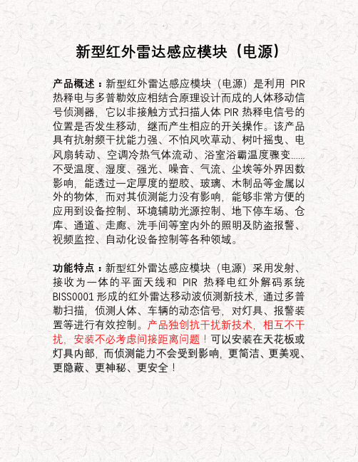
新型红外雷达感应模块(电源)产品概述:新型红外雷达感应模块(电源)是利用PIR 热释电与多普勒效应相结合原理设计而成的人体移动信号侦测器,它以非接触方式扫描人体PIR热释电信号的位置是否发生移动,继而产生相应的开关操作。
该产品具有抗射频干扰能力强、不怕风吹草动、树叶摇曳、电风扇转动、空调冷热气体流动、浴室浴霸温度骤变......不受温度、湿度、强光、噪音、气流、尘埃等外界因数影响,能透过一定厚度的塑胶、玻璃、木制品等金属以外的物体,而对其侦测能力没有影响,能够非常方便的应用到设备控制、环境辅助光源控制、地下停车场、仓库、通道、走廊、洗手间等室内外的照明及防盗报警、视频监控、自动化设备控制等各种领域。
功能特点:新型红外雷达感应模块(电源)采用发射、接收为一体的平面天线和PIR热释电红外解码系统BISS0001形成的红外雷达移动波侦测新技术,通过多普勒扫描,侦测人体、车辆的动态信号,对灯具、报警装置等进行有效控制。
产品独创抗干扰新技术,相互不干扰,安装不必考虑间接距离问题!可以安装在天花板或灯具内部,而侦测能力不会受到影响,更简洁、更美观、更隐蔽、更神秘、更安全!模块类型1、交流型:A C95-250V宽电压,适应各种不同地区电网电压。
可控硅控制A C输出,无触点、无噪音、无污染、寿命长。
具有自动测光管理功能(出厂未安装光敏电阻),实现白天(光线充足)呈关闭状态,晚上(光线不足)人来灯亮、人走灯灭。
可做吸顶灯、日光灯及各种灯具、电器等的自动控制。
交流模块技术参数❖工作电压:A C110V-250V(50-60H z)❖负载功率:阻性负载150W(节能灯、L E D灯80W)❖输出方式:可控硅控制、A C交流输出❖自身功耗:静态功耗≤1m W❖感应范围:10-15米❖感应角度:墙壁安装180°、吸顶安装360°❖触发方式:雷达扫描、人体感应、重复触发❖延时时间:30秒钟(可定做各种延时时间)❖模块尺寸:36m m*23m m*23m m❖环境温度:-30℃-70℃2、直流型:D C6-24V输入,有人在感应区活动时,输出高电平,无人活动时转换为低电平。
U-SIN-RD80-CN2 低频雷达物位计 使用说明书

杭州联测自动化技术有限公司 服务电话:400-185-1718更多资讯请扫二维码杭州联测自动化技术有限公司 U-SIN-RD 80-CN 2第2版低频雷达物位计使用说明书前言●感谢您购买本公司产品。
●本手册是关于产品的各项功能、接线方法、设置方法、操作方法、故障处理方法等的说明书。
●在操作之前请仔细阅读本手册,正确使用本产品,避免由于错误操作造成不必要的损失。
●在您阅读完后,请妥善保管在便于随时取阅的地方,以便操作时参照。
注意●本手册内容如因功能升级等有修改时,恕不通知。
●本手册内容我们力求正确无误,如果您发现有误,请与我们联系。
●本手册内容严禁转载、复制。
●本产品禁止使用在防爆场合。
版本U-S IN-RD80-CN2第二版2021年7月确认包装内容打开包装箱后,开始操作之前请先确认包装内容。
如发现型号和数量有误或者外观上有物理损坏时,请与本公司联系。
产品清单目录第一章产品概述 (1)1.1原理 (1)1.2应用介绍 (2)第二章仪表介绍 (3)第三章仪表安装 (9)3.1安装步骤及注意 (9)3.2安装位置指导 (9)3.2.1锥形罐的安装 (10)3.2.2有堆料的储罐 (11)3.3罐内安装说明 (12)3.3.1最佳安装选择 (12)3.3.2棒式雷达安装说明 (13)3.3.3喇叭口雷达安装说明 (14)3.3.4安装短管较长时使用天线延伸管 (14)3.4容器接管高度要求 (15)3.5导波管中测量 (15)3.6常见安装位置的正误 (18)第四章电气连接 (20)4.1供电电压 (20)4.2连接方式 (20)4.3安全指导 (21)4.4防护等级 (21)第五章仪表调试 (22)5.1雷达物位计有三种调试方法 (22)5.2显示/按键 (22)5.3上位机调试 (23)5.4HART手持编程器编程 (24)第六章结构尺寸(单位:mm) (25)6.1表壳尺寸 (25)6.1.1铸铝表壳 (25)6.1.2塑料表壳 (26)6.2外观尺寸 (27)6.3喇叭口尺寸(单位:mm) (31)6.4法兰选型(单位:mm) (32)第七章技术参数 (33)第八章维护与检修 (36)8.1注意事项 (36)第九章质保及售后服务 (37)第一章产品概述第一章产品概述1.1原理雷达物位计天线发射极窄的微波脉冲,这个脉冲以光速在空间传播,碰到被测介质表面,其部分能量被反射回来,被同一天线接收。
T8 LED微波感应模块参数
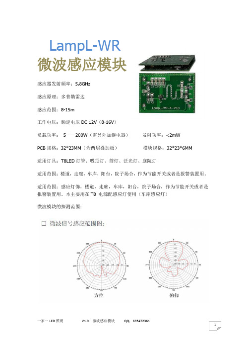
LampL-WR微波感应模块 感应器发射频率:5.8GHz感应原理:多普勒雷达感应范围:8-15m工作电压:额定电压DC 12V (8-16V )负载功率: 5——200W (需另外加继电器) 发射功率:<2mWPCB 规格:32*23MM (为两层叠加板) 模块规格:32*23*6MM 适用灯具:T8LED 灯管、吸顶灯、筒灯、泛光灯、庭院灯适用范围:楼道,走廊,车库,阳台,院子场合,作为节能开关或者是报警装置用。
适用范围:感应灯饰,楼道,走廊,车库,阳台,院子场合,作为节能开关或者是报警装置用。
本主要用在T8 电源配感应灯使用(车库感应灯)微波模块的探测范围:概述:本产品为多普勒雷达技术的自动感应控制产品,灵敏度高,感应距离远,可靠性强,感应角度大,供电电压范围广等特点。
广泛应用于各种人体感应照明的场合,防盗报警场合。
功能特点:本微波感应采用先进技术采用平面天线发射及接受微波本微波感应采用开关为主动式传感器,感应器发射高频电磁波(5.8GHz)并接收他们的回波。
此感应器探测回波内的变化甚至是真探测范围内微小的移动,然后微处理器触发,执行指令.信号通过门、玻璃板及薄的墙壁都有可能被探测到,注意:人或物体向着感应器移动时的探测效果最好!本产品抗干扰能力强,几乎不受风,热等外籍环境因素的干扰,不会随使用时间的延长而缩短感应距离。
很好地避免了红外人体感应的缺点,真正实现了可靠的移动感应器。
技术参数:1.电源电压:DC 12V (或8-16V )2.安装方式:壁挂安装、吸顶安装、T8 两头内置安装3.发射功率:<2mW4.负载功率:可以作为触发信号用,也可以按要求加装继电器。
5.探测角度:180°6.探测距离:8-15m7.工作延时:默认约是30秒(如需其他时间自行调整。
可调整电子版背面斜着的电阻R15B电阻大小来改变时间长短)大批量可以定制(5K PCS))8.探测距离:默认约是8m(如有其他需求可以自行调整。
HB100使用说明

HB100 微波模块使用说明书敬告请在本说明书限定和允许的条件下正确使用本品,任何高于本品承受力的外界环境和输入将会对其造成不可修复的损坏。
无特别情况不可对本品做破坏性和极限承受度试验,这样的试验亦会对其造成不可逆转之损坏焊接注意:请使用低压烙铁焊接并将烙铁可靠接地,焊接DIP的PAD时,需要焊接有有电路走线或者敷铜的那一面!!HB100微波模块是利用多普勒雷达(Doppler Radar)原理设计的微波移动物体探测器,主要应用于自动门控制开关、安全防范系统、ATM自动提款机的自动录像控制系统、火车自动信号机等场所。
HB100是标准的10.525GHz微波多普勒雷达探测器,这种探测方式与其它探测方式相比具有如下的优点:1、非接触探测;2、不受温度、湿度、噪声、气流、尘埃、光线等影响,适合恶劣环境;3、抗射频干扰能力强;4、输出功率小,对人体构不成危害;5、远距离:探测范围超过20米。
多普勒原理简介:多普勒理论是以时间为基础的,当无线电波在行进过程中碰到物体时该电波会被反射,反射波的频率会随碰到物体的移动状态而改变。
如果无线电波碰到的物体的位置是固定的,那么反射波的频率和发射波的频率应该相等。
如果物体朝着发射的方向移动,则反射回来的波会被压缩,就是说反射波的频率会增加;反之反射回来的波的频率会随之减小。
根据多普勒原理设计的微波探测器由FET介质DRO微波震荡源(10.525GHz)、功率分配器、发射天线、接收天线、混频器、检波器等电路组成(图2)。
发射天线向外定向发射微波,遇到物体时被反射,反射波被接收天线接收,然后到混合器与振荡波混合,混合、检波后的低频信号反应了物体移动的速度采用10.525GHz 的微波与采用较低频段波相比有以下优点:1、微波天线发射时具有良好的定向性,因此很容易控制微波探头的作用范围。
2、微波在传输过程中较易被衰减、吸收和反射,遇到墙壁等遮挡物时会被遮挡,因此墙壁等遮挡物外的物体对其干扰很小。
主流微波雷达人体红外感应LD602芯片规格书

主流微波雷达人体红外感应LD602芯片规格书一、概括LD602是一款专为热释电红外传感器信号放大及处理输出的数模混合专用芯片,内部集成了运算放大器、双门限电压比较器、参考电压源、延时时间定时器和封锁时间定时器及状态控制器等,专用于防盗报警系统、人体门控制装置、照明控制开关等场合。
LD602电源工作电压为+3V~+6V,采用CMOS工艺数模混合相结合的集成电路,8个引脚数封装设计,降低了外围电路元件数和整体成本,节省了PCB板空间。
二、应用场合■红外报警器/语音迎宾器■红外感应灯■自动门控控制■自动灯光照明系统■微波雷达感应开关■森林防火报警器三、主要特点●静态功耗小,3V工作电源时功耗小于45uA,5V工作电源时功耗小于75uA,非常适合电池供电系统应用,QQ:298391364●高输入阻抗运算放大器,可与多种传感器匹配,进行信号处理,可作为微波人体感应处理芯片●双向鉴幅器,可有效抑制干扰●内置参考电压,供内部比较器和运放的参考电压●内设延时时间定时器和封锁时间定时器,改变振荡器频率即可设定定时延时时间●8脚红外热释电专用芯片,外围电路简单,成本低●外围元器件少,只需配置第一级运放的增益和振荡器的RC器件即能可靠工作●工作电压+3V~+6V●封装形式SOP8●包装方式管装四、引脚定义五、引脚说明引脚号引脚名功能描述1OUT1内部第一级运放的输出端2IN1内部第一级运放的输入端3VC 触发禁止端当该脚VC电压<0.2Vdd时,禁止触发,即输出信号OUT一直保持低电平当该脚VC电压>0.2Vdd时,允许触发,即输出状态跟随输入信号触发4A 可重复触发和不可重复触发控制端当A=“1”时,允许重复触发当A=“0”时,不可重复触发5GND芯片地6OUT2控制信号输出端,高电平有效输出7CT 振荡器控制端,该脚需对地外接一个振荡电容和对Vdd外接一个上拉电阻8VIN电源输入端,范围3V~6V六、经典常用电路红外感应应用电路微波人体感应方案其中Q2为微波三极管,天线为板载微波天线。
HX801雷达感应模块规格书
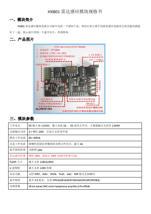
HX801雷达感应模块规格书一、模块简介HX801雷达感应模块是我公司新开发的一个感应产品,和同行的主要不同就是感应电路其它的功能电路做在了一起。
核心就只用到一个蓝牙芯片,外围简单。
二、产品图片qq:298391364三、模块参数工作电压DC输入6---12VDC,输入电流2A,DC座内正外负,正极接触点为直径2.0MM功放输出功率4Ω喇叭20W,目前只支持单声道静态工作电流40---60MA动态工作电流跟喇叭的阻抗和播放的音频文件有关,最大2A蓝牙接收距离无障碍15M雷达感应距离裸机15M,装机后10M内(感应距离可调)FLASH大小最大支持128bit(16M)U盘规格最大支持128G容量音乐功能支持MP3、WAV、WMA、FLAC、AAC、APE格式无损解码蓝牙特性蓝牙5.0版本,支持HFP/A2DP/AVRCP/HSP/GAVDP/I0P/SPP/BLE/音频参数16-bit stereo DAC witch headphone amplifier,S/N>=95db四、模块功能说明1、支持蓝牙连手机音乐播放2、支持U盘MP3播放3、支持外音输入播放4、支持内置FLASH感应播放5、支持红外摇控器6、支持雷达感应白天不工作,晚上感应工作,只要在指定位置加一个光敏电阻就可以实现7、支持9路一对一按键操作文件夹播放(该功能需要定制)8、支持4个按键操作,1、MODE键,2、音量加/下一曲键,3、音量减/上一曲键4、播放/暂停键五、产品特点1、雷达感应电路和语音板放在了一起,物料成本和生产成本明显降低2、感应原理是多普勒效应原理,有穿透非金属物质的特性,成品面板可以不用开窗,保护了产品的美观3、方案支持蓝牙、U盘、外接音频输入播放功能4、产品集成度高,整体使用外围元件少5、方案支持白天不播报功能,只需增加一个光敏电阻即可6、方案定制灵活,外接按键可以支持9路一对一文件夹播放,也可定制支持蓝牙串口和BLE数传、SPP透传7、感应角度为180度8、支持蓝牙音乐播放的语音播报器,这个功能目前大多数类似产品不支持这个功能注意:目前方案只支持感应播放内置FLASH指定文件夹音频文件,其它设备不支持感应播放,需定制才可能实现。
- 1、下载文档前请自行甄别文档内容的完整性,平台不提供额外的编辑、内容补充、找答案等附加服务。
- 2、"仅部分预览"的文档,不可在线预览部分如存在完整性等问题,可反馈申请退款(可完整预览的文档不适用该条件!)。
- 3、如文档侵犯您的权益,请联系客服反馈,我们会尽快为您处理(人工客服工作时间:9:00-18:30)。
高频低压感应模块规格书
一、型号
1、FCX-D3(外形尺寸18X25X5mm)
2、FCX-D1(外形尺寸23X32X5mm)
二、参数
1、电源电压:5-16VDC;
2、发射功率:≦2mW;
4、输出信号:TTL电平,高有效;
5、探测角度:180°(半球面);
6、探测距离:3-8米(订购时可选),默认设定5-8米。
(调节方法见备注附件)
7、工作延时:10秒到120秒(订购时可选),默认设定30秒。
(调节方法见备注附件)
三、接线图
Vcc
Vcc 感应模块FCX-D1(背面)
感应模块
FCX-D3(背面)GND Vout GND Vout Vcc :电源端,电源电压直流6—15V ;
DNG :接地端
Vout :信号输出端,默认输出 TTL 电平;可开关量输出,具体方法见备注附件。
四、高频感应模块的功能与特点:
1、智能感应:当有人进入本产品的探测范围,高频感应模块输出端 Vout 输出 TTL 高电平,经过一个延时周期(10-120秒可设定),输出端恢复到 TTL 低电平。
2、智能延时:感应模块启动后,在延时时间段内,如有人体活动,模块输出端 Vout 将持续输出 TTL 高电平,直到人离开并经过一个延时周期后输出低电平。
3、光敏控制(可选项):根据外界的光线强度,控制模块的输出状态,达到节能效果。
4、与红外产品比较:高频感应模块感应距离更远,角度广,无死区,不受环境温度、灰尘等影响。
高频感应模块是红外和声控感应模块理想的更新换代产品。
产品应用:玩具、照明、开关、家电、医疗、工业、安防、军事等
深圳市佳伟思智能照明有限公司。