台湾泰仕回路阻抗预期短路电流测试器TES1800A
TestVonics ADTS-3350系列飞行线空气数据测试设备说明书

High PrecisionRVSM CompliantRugged, compact durable design for Flightline Applications Calibrate, test and troubleshoot Aircraft & Instruments ADTS-3350 is common equipmentthat can be used for a variety of Commercial Aircraft NSN: 4920-01-662-3920P/N: ADTS-3350ER(Ext. Range) ADTS-3350MR (Mid Range) ADTS-3350LR (Low Range)ADTS-3350 Series Flight Line Air Data Test Set TestVonics ADTS-3350 Series Test Set is a portable, high precision, dual channel air data pressure management system. This tester is designed to calibrate, test and troubleshoot air data instrumentation and aircraft pitot-static systems. The test set has been designed with functional and reliability features highly suited to withstand the harsh environmental and demanding conditions of the flight line environment. The test set is designed for testing a wide range of commercial and military aircraft, both rotary and fixed wing. The ADTS-3350 accuracy complies with standards for RVSM. FeaturesThe ADTS-3350 features a brilliant 8.4-inch transflective, high-bright ruggedized L CD display. The display features an optically bonded resistive touchscreen and adjustable LED backlighting, which provide optimal visualization and viewing angle in direct sunlight. The backlit keypad is used to control the test set and can be easily operated using gloves or mittens. The ruggedized case features recessed hardware, a replaceable retractable handle and durable wheels for excellent maneuverability and single operator transport. The ADTS operates from 90-260 VAC, 45-440 Hz power, making it ideally suited for the varying hangar, ramp and flight line power sources.Simple and Intuitive InterfaceThe ADTS-3350 software features an intuitive graphical interface which has been designed to virtually eliminate the operator learning curve. Mode of operation can be cycled while testing and the display is uncluttered and easy to read. Protection and Safety FeaturesThe ADTS-3350 Series is designed with both hardware and software safety features designed for maximum protection when testing. The test set features input pressure regulation, over-range, over-limit and over-pressurization protection. Micro-porous filters and screening prevent debris from entering the system. The test set is equipped with pressure relief valves to protect the pneumatic system components and the Unit Under Test (UUT) from damage. In the unlikely event that the test set loses power, the UUT is isolated. The manual vent switch on the front panel can then be used to safely vent both the test set and the UUT to ambient.The ADTS features an Aircraft Select Mode, which allows the operator to select pre-installed or customized Aircraft or UUT. Once set, the software automatically limits the ranges and rates for the specific aircraft under test. Test profiles can be created for routine testing, providing improved test consistency.Remote OperationThe ADTS-3350 Series has two (2) Remote Control Units available. Both units feature color touchscreens, one is a tablet style and the other features a color coded keypad. Both remotes feature a similar display format as the main unit. A 25ft remote cable is included. Automated CalibrationThe ADTS-3350 can be calibrated automatically through software. Corrections are done through software requires no mechanical adjustments. The transducers are able to hold their accuracy for a period of one year.ADTS-3350 Air Data Test Sets TestVonics™ Flightline Digital Air Data Test SetsTestVonics Incorporated 375 Jaffrey RoadPeterborough, NH 03458CAGE: 1A9E1Phone: (603) 924-5922 Web: © Copyright 2018. ADTS-3350.V .A5TestVonics, Inc. All rights reserved.Telescoping 3-stage retractable handleRecessed grasp handlesFront Panel Features Remote Control Unit1) Standard ranges listed. Ranges may be configured to comply with customer specific requirements - contact TestVonics for more information † -10,000 to 99,000 ft Altitude Range is also available per customer requirement. 2) The Altitude and Airspeed Slew Rates are load dependent. Slew rates and load test requirements may vary based on volume of the DUT. 3) Standard units of measurement listed (at time of print). Additional units may be available upon user request.Colors3.5” color, sunlight readable touchscreendisplay New! Composite ADTS Case with Air Data ManifoldHandheld Remote Control Unit (RCU) OptionsAirspeed Pitot (Pt) input Altitude Static (Ps) input 8.4” LED Touch Display Backlit Color Keypad 9. Remote Control port 10. Service port 11. Manual Vent 12. Moisture Vent5. External Ground6. Power Switch7. Power/Line Indicator 8. AC Power Input Remote Control Unit NSN: 7035-01-662-3604New! Tablet style Remote Control Unit (available 2019)7.0” colorsunlight readable projected capacitive (PCAP) touchscreenIntegrated 5 port Pitot / 5 port Static Air Data Manifold (optional) Ruggedized IP67-rated impact resistant case. Certified to ATA 300, ASTM D4169 and MIL-STD-810F specification Large soft grip handlesField replaceable2-stage retractable handle withpolyurethane wheels Automatic Pressure Relief Valveall Stainless SteelHardwareSpring loaded soft grip sidehandles567Ruggedized wheelsRubber Bumpers。
维亚视网络测试仪T-BERD MTS-5800 IEEE 1588v2 PTP 同步测试指南说明书
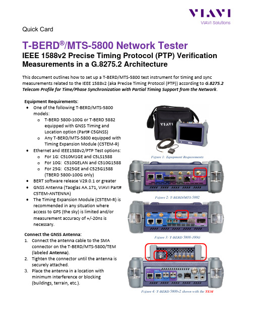
Quick CardT-BERD®/MTS-5800 Network TesterIEEE 1588v2 Precise Timing Protocol (PTP) Verification Measurements in a G.8275.2 ArchitectureThis document outlines how to set up a T-BERD/MTS-5800 test instrument for timing and sync measurements related to the IEEE 1588v2 (aka Precise Timing Protocol (PTP)) according to G.8275.2 Telecom Profile for Time/Phase Synchronization with Partial Timing Support from the Network. Equipment Requirements:•One of the following T-BERD/MTS-5800models:o T-BERD 5800-100G or T-BERD 5882equipped with GNSS Timing andLocation option (Part# C5GNSS)o Any T-BERD/MTS-5800 equipped withTiming Expansion Module (C5TEM-R)•Ethernet and IEEE1588v2/PTP Test options:o For 1G: C510M1GE and C5LS1588o For 10G: C510GELAN and C510G1588o For 25G: C525GE and C525G1588(TBERD 5800-100G only)•BERT software release V29.0.1 or greater •GNSS Antenna (Taoglas AA.171, VIAVI Part# C5TEM-ANTENNA)•The Timing Expansion Module (C5TEM-R) is recommended in any situation whereaccess to GPS (the sky) is limited and/ormeasurement accuracy of +/-20ns isnecessary.Connect the GNSS Antenna:1.Connect the antenna cable to the SMAconnector on the T-BERD/MTS-5800/TEM(labeled Antenna).2.Tighten the connector until the antenna issecurely attached.3. Place the antenna in a location withminimum interference or blocking(buildings, terrain, etc.).Figure 1: Equipment RequirementsFigure 2: T-BERD/MTS-5882Figure 3: T-BERD 5800-100G Figure 4: T-BERD 5800v2 shown with the TEMEnable GNSS Receiver and Complete Survey:1. Press the Power buttonto turn on the test set. 2. Tap the Test icon .3. Tap the Internal GNSS tabor the Timing Source tab.4. Tap the Setup soft key .5. Configure GNSS Settings as follows:• GNSS System(s): Select GPS for use in North America. Other constellations or combination of constellations can also be used.• Time Type : GPS• Time Format : 12-hourFigure 5: GNSS Setup• Elevation Limit: 5 deg recommended and will work in “urban canyon” environments with many obstructions. Using satellites near the horizon may degrade performance so using an Elevation Limit greater than 5 but less than 15 degrees is acceptable.• Minimum C/No : 9 dB-Hz reco mmended and will work in “urban canyon” environments with many obstructions. Using satellites with a weak carrier to noise ratio may degrade performance so values as high as 30 dB-Hz are acceptable for “clear -key” environments.• Antenna Power : 3.3 volts for VIAVI supplied Taoglas AA.171 antenna. If you are using a different antenna, enter the voltage required by that antenna. Enter “0” if the antenna has a power source.• Antenna Time Bias : 28 ms for VIAVI supplied Taoglas AA.171 antenna. If you are using a different antenna, enter the cumulative delay introduced by the antenna, the cables, and any in-line splitters, surge arresters or amplifiers. In absence of more specific information, use 1.2ns/foot or 4.5ns/meter of cable.6. Tap the Location settings tab .7. Configure Location Settings as follows:• Survey mode: Typical (3 hours) theminimum recommended survey length for best accuracy. Fast or Quick may be used, but timing accuracy is reduced. 8. Tap the Start Survey buttonto start asurvey.9. Tap the Results soft key to view the TestResult screen.10. If you are using a T-BERD 5800v2 and TimingModule (C5TEM-R), tap the Rubidium Osc.button to turn on and tune theoscillator.Figure 6: Location SetupFigure 7: Test Results Screen, T-BERD 5800v2ing the results group and category drop-down menus, change the left or rightdisplays to the following:•Satellites/Sky Plot: Displays thesatellites detected by the GNSSreceiver. Ensure at least 4 satellitesare “Used”. Otherwise, relocateantenna to a less obstructedlocation.•GNSS/Location: Provides the mean(avg) C/No, the 3D LocationAccuracy, and the Current (duringsurvey) and Mean Position Dilutionof Precision (PDOP). A PDOP of 1 isperfect. A value below 4.0 is desired.•Satellites/Signal Strength: Uses abar graph to display the signalstrength for each identified satellite.Green indicates the signal is abovethe Minimum C/No setting.•GNSS/Status: Displays generalinformation concerning the GNSSSatellites. Ensure that Statusprogresses from “No Lock” to“Locked” to “Fixed Position” duringthe survey. Ensure that TimingMode Status progresses from“Survey” to “Survey Done”.Note: If you are using a T-BERD 5800v2and Timing Module (C5TEM-R), theSummary LED and Summary/Statusresults display will remain red until therubidium oscillator is tuned.12.Once the survey is done (oscillator is in FineTune state if using TEM), you are ready toperform timing tests using the attachedantenna, including:•One-way delay measurements•IEEE 1588 Precision Time Protocol(PTP) Time Error, and Packet DelayVariation (PDV) measurements•Wander analysis•Timing and 1PPS AnalysisFigure 8: Satellites/Sky Plot resultsFigure 9: Satellites/Signal Strength results Figure 10: GNSS/Status after survey (Internal GNSS)Figure 11: GNSS/Status after survey & course tune (TEM)Enable PTP Slave Session:1.Tap the second folder under the Test Iconat the top of the screen.2.Tap the Select Test drop-down andselect the Layer 4 PTP/1588 at the desiredrate:•Ethernet> 1GigE Optical>Layer 4 PTP/1588> IPv4> P1Terminate•Ethernet> 10GigE LAN>Layer 4 PTP/1588> IPv4> P1Terminate•Ethernet> 25GigE LAN>Layer 4 PTP/1588> P1 Terminate 3.Connect T-BERD SFP+ Port 1 to the networkport to be tested using an LC patch cable.•Enable the Laser:•Press Restart:•Look for 5 or 6 green LEDs: This will indicate that the link is up, and GPSsourced timing is available.•Press Setup:4.Select the All Streams folder. ConfigureSource IP Type, Source IP and DefaultGateway.5.Select the PTP Folder. Make all PTP settingsas necessary as a PTP Slave on the network under test.•Mode: Slave•Domain: default value should be set to 44, otherwise use the valuerecommended by your networktiming administrators•Address Mode: Multicast or Unicast•Master IP Address: example shown•Encapsulation: None or VLAN andenter VLAN ID & VLAN Priority6.Press Results: to return.7.In the Actions tab, press Start Slave PTPSession. Figure 12: Test SelectionFigure 13: Physical Layer EstablishmentFigure 14: All Streams setupFigure 15: PTP Slave ParametersFigure 16: Actions Tab to Start PTP SessionFigure 17: Session StartedContact Us +1 844 GO VIAVI(+1 844 468 4284)To reach the VIAVI office nearest you,visit /contacts.© 2021 VIAVI Solutions Inc.Product specifications and descriptions in thisdocument are subject to change without notice. .Thresholdsand set desired thresholds.tab, pressIf any of the thresholds are triggered the Figure 18: PTP Test Results Figure 19: PTP Test Results Figure 20: PTP Thresholds Figure 21: PTP Test Results。
Agilent dc电子负载N3300A-N3307A数据手册说明书

Agilentdc Electronic LoadsModels N3300A-N3307AData SheetIncrease your manufacturing test throughput with fast electronic loads• Increase test system throughput• Lower cost of ownership• Decrease system development time• Increase system reliability• Increase system flexibility• Stable operation down to zero volts• dc connection terminal for ATE applicationsIncrease Test Throughput Today’s high volume manufacturing requires optimization of test system throughput, to maximize production volume without increasing floorspace. The N3300A Series electronic loads can help you in a number of ways to achieve this goal.Reduced command processing time: Commands are processed morethan 10 times faster than previous electronic loads.Automatically execute stored command sequences: “Lists” of downloaded command sequences can execute independent of the computer, greatly reducing the electronic load command processing time and computer interaction time during product testing. Programmable delay allows foreither simultaneous or sequential load changes: This is the most efficient way to conduct testing of multiple output dc power supplies, simulating real-life loading patterns, with a minimum of programming commands.Buffer measurement data: Voltage, current, and power measurements can be buffered for later readbackto the computer, reducing computer interaction.Control measurement speed vs. accuracy: Decrease the number of mea-surement samples to achieve greater measurement speed, or increase the number of samples to achieve higher measurement accuracy. You can opti-mize your measurements for each test. Control rising and falling slew rates separately: Reduce rate of loading change when necessary for DUT stabil-ity or to simulate real life conditions, but otherwise change load values at maximum rate.Increase SystemFlexibility…for BothPresent and FutureRequirementsMost power supply and batterycharger test systems designed todayneed to test a variety of productsand/or assemblies. In the future,additional products or assemblies maybe needed. A flexible family of electronicloads makes present system design andfuture growth much easier.T est low voltage power supplies:The N3300A series electronic loadsoperate with full stability down to zerovolts. Many other electronic loads avail-able today have been found to becomeunstable in the operating region belowone volt. When designing power supplytest platforms, the trend towards lowervoltage requirements should be takeninto account. Refer to the specificationand supplemental characteristic tablesfor details of lower voltage operatingcharacteristics.Choose dc load connection method:Automatic test systems needconsistency and reliability. Option UJ18 mm screw connectors provide asimple screw onto which your wires,terminated with insulated ringterminals, may be securely mounted.This optional connector is specificallydesigned for test systems. Wires mayexit the plastic cover in any direction,and multiple wires may be placed oneach screw terminal for easy parallelload connections. Up to AWG 4 wiremay be used.Applications which require repeatedconnections/disconnections are bettersuited to the standard connector.The standard connector accepts anunterminated wire, and may be hand-tightened. This connector is specificallydesigned for bench applications andshort-term automated tests.Design a system to test a variety ofproducts: This series consists of2 mainframes and 6 modules. TheN3300A mainframe is full rack width.It has 6 slots. The N3301A mainframeis half rack width. It has 2 slots. Anyassortment of the 6 different modulescan be configured into these main-frames, up to the slot capacity. TheN3302A (150watts), N3303A (250 watts),N3307A (250 Watts) and N3304A(300 watts) each require one slot. TheN3305A (500 watts) and the N3306A(600 watts) each require 2 slots. Theelectronic load can be configured tosupply exactly what you need now, andthis modular design also allows foreasy future reconfiguration.Test high current power supplies:Electronic load modules can beoperated in parallel to provideadditional current sinking capability.Standard dc connectorsOption UJ1 8 mm screw connectorsControl the electronic load how you want to: GPIB, RS232, and manualuse of the front panel all provide complete control of these electronic loads. There are also analog program-ming and monitoring ports for those applications that utilize nonstandard interfaces, require custom waveforms, or utilize process control signals. Custom waveforms can also be created by downloading a “List” of load para-meters. In addition, there is a built-in transient generator, which operates in all modes.Quickly create powerful and consistent software: All Agilent Technologies electronic loads usethe SCPI (Standard Commands for Programmable Instruments) command set. This makes learning the commands easy, because they are the same format as all other SCPI instruments. The resulting code is virtually self-documenting, and therefore easier to troubleshoot and modify in the future. Plug-n-Play drivers are also available to help you to integrate the loads into your standard software packages.Make MeasurementsEasily and AccuratelyThe 16-bit voltage, current and powermeasurement system provides bothaccuracy and convenience. The alterna-tive is using a DMM (digital multimeter)and MUX (multiplexer) along with aprecision current shunt and a lot ofextra wiring. Avoiding this complexityincreases system reliability and makesthe system easier to design and support.Current measurements in particularare more consistently accurate usingthe electronic load’s internal system,because the wiring associated with anexternal precision current shunt maypick up noise.Measure with all load modulessimultaneously: T esting multiple outputdc power supplies and dc-dc converterscan be very time consuming if eachoutput must be tested sequentially. Ifmeasurements are being made througha MUX using one DMM, this is what willhappen. Using the built-in measurementcapabilities of the N3300A electronicloads, all outputs can be measuredsimultaneously. Alternatively, multiplesingle output power sources can betested simultaneously.Measure voltage and currentsimultaneously: The N3300A measure-ment system has individual but linkedcurrent and voltage measurementsystems. This means that voltageand current measurements are takenexactly simultaneously, which gives atrue picture of the power supply undertest’s output at a particular momentin time. Some other electronic loadswhich feature internal measurementsystems actually take current andvoltage measurements sequentially,and therefore do not give as accurate apicture of momentary power.Observe transient behavior usingwaveform digitization: Transientresponse and other dynamic tests oftenrequire an oscilloscope. The N3300Ahas a flexible waveform digitizer with a4096 data point buffer for voltage anda 4096 data point buffer for current.Under many circumstances, thisinternal digitizer will be adequate forpower supply test needs. Current andvoltage are digitized simultaneously,and the sampling rate and samplewindow are programmable. Someanalysis functions are provided,including RMS, max and min.N3302A N3303AN3304AN3305AN3306AN3307ASpecified current @ low voltage operationSpecificationsTable A-1 lists the specifications for the different load models. Specifications indicate warranted performance in the 25°C ±5°C region of the operating temperature range. Specifications apply to normal and transient modes unless otherwise noted.Table A-1Operating contourDerated current detailMax. power contourN3302A N3303AN3304AN3305AN3306AN3307ATypical minimum operating voltage @ full scale current1.2 V1.2 V1.2 V1.4 V1.4 V1.4 VTable A-1 states that maximum current is available down to 2 volts. Typically, however under normal operating conditions, the load can sink the maximum current down to the following voltages:Table A-1 Specifications (continued)SupplementalTable A-2 lists the supplemental characteristics, which are not warranted but are descriptions of typical performance determined either by design or type testing.SupplementalTable A-3N3300A N3301AOperating temperature range0°C to 55°C0°C to 55°CInput ratingsOperating range100 - 250 Vac; 48 - 63 Hz100 - 250 Vac; 48 - 63 Hz Input current 4.2 A @ 100 - 127 Vac; 2.2 A @ 200 - 250 Vac 2.3 A @ 100 - 250 VacInput VA440 VA230 VAInrush current38 A18 A @ 115 Vac; 36 A @ 230 VacSupplemental Characteristics (continued) Analog programming bandwidth:10 kHz (-3 db frequency)Analog programming voltage: Voltage: 0 - 10 VCurrent: 0 - 10 VAnalog monitor ports:Voltage: 0 - 10 VCurrent: 0 - 10 VRemote sensing:5 V dc between sense and load input Digital/Trigger inputsVil = 0.9 V max at Iil = -1 mAVih - 3.15 V min (pull-up resistor on input)Digital/Trigger outputsVol = 0.72 V max at Iol = 1 mAVoh = 4.4 V min at Ioh = -20 μANet weight:N3300A: 13.2 kg (29 lb);N3301A: 7.3 kg (16 lb);N3302A, N3303A, N3304A orN3307A: 2.7 kg (6 lb);N3305A or N3306A: 4.6 kg (10 lb) Shipping weight:N3300A: 17 kg (38 lb); N3301A: 9.1 kg (20 lb)N3302A, N3303A, N3304A orN3307A: 4.1 kg (9 lb)N3305A or N3306A: 6.8 kg (15 lb)OptionDescriptionsOption UJ1:8 mm screw terminal connector Option 800:Rack-mount kit for two N3301A Mainframes mounted side-by-side (p/n 5061-9694 and 5062-3978). Option 908:Rack-mount kit (Two p/n 5062-3974 for a N3300A, or p/n 5062-3960 for one N3301A).For the N3301A, the kit includes a blank filler panel.Option 909:Rack-mount kit with handles forN3300A (Two p/n 5062-3975) Option 0L1:English printed Users and Programming Guide.The programming manual is available with the mainframes, and therefore not with the modules.Note:Options 908, 909, and 800 require either the slide kit (p/n 1494-0059) or support rails (E3663AC) to support the weight of the load mainframe.Revised: October 14, 2010Product specifications and descriptions in this document subject to change without notice.© Agilent Technologies, Inc. 2002, 2011Printed in USA, May 17, 20115980-0232E/quality。
testo 315-1 2 使用手册说明书
>7.5 V (电池寿命上 下 滚动键between the parameters,.单位同样可以被改变。
参数设定通过和 键。
All of the saved readings can be printed on the printer via the 通过 键按 键确认。
关 开testo 315-1CO • hPa µA • °C/°F 电离电流 探头接入端CO 密封帽必须关紧。
/程序段测试 (3 s)167CO167167按 键,显示所有程序段约秒钟。
位数)显示电池/充电电池电压以及显示模式显示模式 (3 长按 键秒钟,显示3位数的显示模式。
初始状态持续约 符号如图显示在显示屏上。
初始状态后,仪器自动进入测量菜单。
automatically goes to the measurement menu.密封帽必须处在闭合状态。
否则,“ 3 s5 s功能测试/使用前需进行功能测试连接软管/CO 密封帽必须盖紧./ 打开密封帽程序段测试 (3 s)152157CO 密封帽必须盖紧 /打开密封帽程序段测试 (3 s)显示电压 (3 s)符号: /测量范围162154167152 关上CO 密封帽.程序段测试 (3 s)- 功能测试测量菜单功能测试。
/当CO 若密封帽在启动时被打开,进程将被打断,在密封帽盖紧后将重新启181181保存读数HOLD 器。
接上测试夹时可能产生电流,这可能会干扰到仪器的警报系统。
in the instrument warning system. 连接测量线红色+/黑色密封帽必须盖紧./程序段测试 (3 s)打开密封帽T o avoid an electric shock it 在高于(25) eff AC 时,为了避免电击,请务必注意安全和遵守术工程师协会危险的规定。
observed when working with voltages greater than 120V (60V) DC or 50V 括号内的数值仅限于特殊领域(如:医药,农业)。
SENTRON 7KM PAC3200 电能计量仪产品说明书

09/04/2017
Subject to change without notice © Copyright Siemens
National language / on the display screen / is supported Horizontal image resolution Vertical screen resolution
General technical data Cutout width Cutout height Size of Power Monitoring Device / company-specific Operating mode for measured value detection ● automatic line frequency detection ● set at 50 Hz ● set to 60 Hz Pulse duration ● initial value ● Full-scale value
09/04/2017
Subject to change without notice © Copyright Siemens
Voltage curve Measurable line frequency / initial value Measurable line frequency / Full-scale value Measuring procedure / for voltage measurement MTBF Equipment marking / acc. to DIN 40719 extended according to IEC 204-2 / acc. to IEC 750
45 Hz 65 Hz DC CATIII
SENTRON 3VA2710-2AC05-0AA0 1600A 三相固定挂载电路保护器说明书
General Product Approval
36 kA
Main connection at the front, extension enclosed busbar connection
3VA27102AC050AA0 Page 1/4
fixed-mounted molded case circuit breaker frame 1600; with RTC and 4AUX trip alarm switch S24; Icu "H" Icu=85kA @ 415V, 3-pole ETU350, LSI, In=1000A rotary coding switch Ir=400...1000A Isd=1...10xIn, Ii=1.5...15xIn N conductor protec. adjustable opt. w. ext. CT; up to 200% straight bus connector extended No communication connection, no measurement function Manual operating mechanism of the spring energy store With mechanical calling without 2nd auxiliary release without 1st auxiliary release
3VA27102AC050AA0 Page 2/4
7/10/2023
Subject to change without notice © Copyright Siemens
安全性能综合测试仪使用手册

安全性能综合测试仪(42系列)使用手册检定规程:JJG984—2004 国家接地电阻测试仪计量检定规程JJG795—2004 国家耐电压测试仪计量检定规程JJG1005-2005 国家电子式绝缘电阻表计量检定规程JJG 843-2007《泄漏电流测试仪计量检定规程》执行标准:Q/0205OSD001—2009 96系列安全性能测试仪企业标准目录第一章安全规则 (1)1.1一般规定 (1)1.2维护和保养 (1)1.2.1使用者的维护 (1)1.2.2定期维护 (2)1.2.3使用者的修改 (2)1.3测试工作站 (2)1.3.1位置选择 (2)1.3.2输入电源 (3)1.3.3工作场所 (3)1.4操作人员规定 (3)1.4.1人员资格 (3)1.4.2安全守则 (3)1.4.3衣着规定 (3)1.4.4医学规定 (3)1.5测试安全程序规定 (4)1.6安全要点 (4)第二章概述 (4)2.1产品简介 (5)2.2产品特点 (5)2.2.1 测试迅速 (5)2.2.2 输出方式先进 (5)2.2.3 运行可靠 (5)2.2.4 操作简单 (6)2.2.5 联机方便 (6)2.3前面板说明 (6)2.4后面板简介 (7)2.4.1柜式综合测试仪后面板 (7)2.4.2台式综合测试仪后面板 (8)2.5 隔离电源输入板(只适用于柜式综测): (9)第三章安装要点 (9)3.1拆封和检查 (10)3.2使用前的准备 (10)3.2.1工作电压的要求和选择 (10)3.2.2输入电压的要求和选择 (10)3.3储存和运输 (10)3.3.1周围环境 (10)3.3.2包装方式 (11)第四章技术指标 (11)4.1整机规格 (12)4.2技术参数 (12)4.2.1接地电阻 (12)4.2.2绝缘电阻 (12)4.2.3耐压测试 (13)4.2.4泄漏电流 (13)4.2.5功率测试 (13)4.2.6启动测试 (14)第五章综合测试仪使用方法 (15)5.1外部接线 (16)5.2测试仪开机 (17)5.3自检 (17)5.4主菜单界面 (18)5.5功能设置 (18)5.5.1设置密码: (19)5.5.2单步测试: (19)5.5.3模拟阻抗(需定制): (19)5.5.4 波特率 (19)5.5.5系统设置保存 (20)5.6密码输入 (20)5.7选择测试组 (20)5.8设置测试项 (21)5.8.1测试方式选择 (22)5.8.2测试频率选择 (22)5.8.3保存设置 (22)5.8.4不保存退出设置 (22)5.9接地测试 (22)5.9.1设置接地测试项 (22)5.9.2开始接地测试 (23)5.10绝缘测试 (24)5.10.1设置绝缘测试项 (24)5.10.2开始绝缘测试 (25)5.11耐压测试 (25)5.11.1设置耐压测试项 (25)5.11.2开始耐压测试 (26)5.12泄漏测试 (27)5.12.1设置泄漏测试项 (27)5.12.2 开始泄漏测试 (28)5.13 功率测试 (28)5.13.1 设置功率测试项 (28)5.13.2 开始功率测试 (30)5.14 启动测试 (30)5.14.1 设置启动测试项 (30)5.14.2开始启动测试 (31)5.15 测试 (32)5.16串行通信 (32)5.17 遥控接口: (34)5.18 关机 (34)第六章维护指南 (35)6.1 首次使用前检查 (35)6.2 日常维护 (35)6.3 简单故障处理 (36)6.4 注意事项 (36)附录1:综合测试仪校准方法 (37)1、引言 (37)2、检定方法 (37)2.1耐电压测试的检定 (37)2.2绝缘电阻测试的检定: (38)2.3接地电阻测试的检定: (39)2.4泄漏电流测试的检定: (40)第一章安全规则本章概要:1.一般规定2.维护和保养3.测试工作站4.操作人员规定5.测试安全程序规定6.安全要点1.1一般规定∙手册内容若有改变,恕不另行通知。
NR1800数字式继电保护测试仪说明书

目录第1章快速入门 (1)第1节软件安装 (1)第2节装置简介 (10)第3节装置整体说明 (14)第4节电流保护试验 (19)第5节电压保护试验 (25)第6节时间继电器试验 (29)第7节中间继电器试验 (33)第8节反时限特性 (36)第9节距离(阻抗)保护试验 (43)第10节零序保护试验 (67)第11节线路整组传动试验 (73)第12节差动保护试验 (78)第13节变送器试验 (95)第14节电能表试验 (100)第15节低周减载试验 (105)第16节同期装置测试 (110)第17节备自投装置试验 (121)附录 1参数设置 (129)1.1.通道配置 (129)1.2.元件定值设置 (131)1.3.元件特性编辑 (132)1.4.网络参数 (141)1.5.结果管理 (142)1.6.报告 (144)1.7.状态量 (146)1.8.GPS触发器 (149)附录2. IEC-61850数字量输出控制 (153)2.1数字量输出接口 (153)2.2数字量输出引入保护装置 (153)2.3启动IEC61850数字配置窗口 (153)2.4IEC61850配置界面 (154)2.5IEC61850-9-1配置 (158)2.6IEC61850-9-2配置 (164)2.7IEC60044-8配置 (170)2.8GOOSE IN配置 (175)2.9GOOSE OUT配置 (178)2.10小信号配置 (181)2.11工具栏 (183)2.12配置文件管理 (185)2.13SCL解析 (188)2.14报文监视 (198)2.15注意事项 (202)索引 (202)第1章快速入门第1节软件安装1.1测试软件的安装1) 将NR 继电保护测试软件安装光盘放入光驱,双击光盘中安装程序,进入安装界面,如图1-1 所示:图1-12) 点击“Next”按钮,继续安装,进入安装选项设置,如图1-2 所示:图1-23) 如果选择默认配置,则直接点击“Next”按钮,进行下一步安装;不然点击“I do not…”按键取消安装,继续安装如图1-3 所示:图1-34) 继续点击“Next”按钮,进入下一步安装,如图1-4 所示:图1-45) 继续点击“Next”按钮,正式开始安装,如图1-5所示:图1-56) 安装结束后将出现安装结束界面,如图1-6所示,点击“Finish”结束安装。
- 1、下载文档前请自行甄别文档内容的完整性,平台不提供额外的编辑、内容补充、找答案等附加服务。
- 2、"仅部分预览"的文档,不可在线预览部分如存在完整性等问题,可反馈申请退款(可完整预览的文档不适用该条件!)。
- 3、如文档侵犯您的权益,请联系客服反馈,我们会尽快为您处理(人工客服工作时间:9:00-18:30)。
" OL " on " " in display
附件
电源线、外部接地测试棒
TES-1800B (110V)
超大数字显示
测试阻抗过热时自动锁住
电压指示
回路阻抗最低文件分辨率 0.01W
高回路阻抗量测
微处理器控制
TES-1800A回路阻抗/预期短路电流测试器技术参数:
回路阻抗档位
20 / 200 / 2000W
回路阻抗正确度
+/- ( 2% + 3 位数 ) at 1W on 20W Range
最小分辨率
0.01W
电压显示
+/- 2% + 2 位数
交流测试电流
25A nominal at 20 Range
交流测试周期
16.67ms
预期短路电流
200A / 2000A / 20KA
操纵电压
230V +/- 10% , 50Hz +/- 1 %
抵文件电压
3000V AC for 1 分钟
保险丝保护
快速溶断陶瓷器保险丝
尺寸
200(长) × 140(宽) × 95(高) 公厘
重量
约 900g
显示
3 1/2 液晶显示器和最大读值 1999.
过载指示
当电表量测过载档位显示器显示" OL "
操纵温度及湿度
0oC to 40oC (32oF to 104oF), Below 80% RH
储存温度
-10oC to 60oC (14oF to 140oF)TES-1800A回路阻抗期短路电流测试器台湾泰仕TES
官网:/
产品名称:
TES1800A回路阻抗/预期短路电流测试器
产品品牌:
台湾泰仕TES
产品型号:
TES1800A
产地:
中国台湾
具体说明:
TES-1800A回路阻抗/预期短路电流测试器简介:
TES-1800A (230V)