EMC Solution
aix_PowerpathSolutionenabler安装
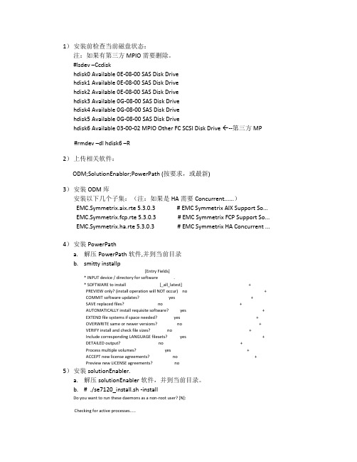
1)安装前检查当前磁盘状态:注:如果有第三方MPIO需要删除。
#lsdev –Ccdiskhdisk0 Available 0E-08-00 SAS Disk Drivehdisk1 Available 0E-08-00 SAS Disk Drivehdisk2 Available 0E-08-00 SAS Disk Drivehdisk3 Available 0G-08-00 SAS Disk Drivehdisk4 Available 0G-08-00 SAS Disk Drivehdisk5 Available 0G-08-00 SAS Disk Drivehdisk6 Available 03-00-02 MPIO Other FC SCSI Disk Drive --第三方MP#rmdev –dl hdisk6 –R2)上传相关软件:ODM;SolutionEnablor;PowerPath (按要求,或最新)3)安装ODM库安装以下几个子集:(注:如果是HA需要Concurrent......)EMC.Symmetrix.aix.rte 5.3.0.3 # EMC Symmetrix AIX Support So...EMC.Symmetrix.fcp.rte 5.3.0.3 # EMC Symmetrix FCP Support So...EMC.Symmetrix.ha.rte 5.3.0.3 # EMC Symmetrix HA Concurrent ...4)安装PowerPatha.解压PowerPath软件,并到当前目录b.smitty installp[Entry Fields]* INPUT device / directory for software .* SOFTWARE to install [_all_latest] +PREVIEW only? (install operation will NOT occur) no +COMMIT software updates? yes +SAVE replaced files? no +AUTOMATICALLY install requisite software? yes +EXTEND file systems if space needed? yes +OVERWRITE same or newer versions? no +VERIFY install and check file sizes? no +Include corresponding LANGUAGE filesets? yes +DETAILED output? no +Process multiple volumes? yes +ACCEPT new license agreements? no +Preview new LICENSE agreements? no5)安装solutionEnabler.a.解压solutionEnabler软件,并到当前目录。
电解液各溶剂简称及其参数

锂电池电解液常用溶剂碳酸丙烯酯:PC分子式:C4H6O3无色无气味,或淡黄色透明液体,溶于水和四氯化碳,与乙醚,丙酮,苯等混溶。
是一种优良的极性溶剂。
本产品主要用于高分子作业、气体分离工艺及电化学。
特别是用来吸收天然气、石化厂合成氨原料其中的二氧化碳,还可用作增塑剂、纺丝溶剂、烯烃和芳烃萃取剂等。
特性分子量:102.09物理性质:外观无色透明液体熔点-48.8 ℃沸点242℃闪点132℃溶解度参数δ=14.5相对密度1.2069溶解度参数[2] δ=14.5饱和蒸汽压0.004kpa溶解性:溶于水,可混溶于丙酮、醇,乙醚、苯、乙酸乙酯等有机溶剂.折光率1.4189比重1.189粘度2.5mPa.s介电常数69c/v.m毒理数据:动物实验经口服或皮肤接触均未发现中毒.大鼠经口LD50=2,9000 mg/kg.质量标准项目指标优级品一级品外观无色或淡黄色液体无色或淡黄色液体含量, %≥99.5≥99.0 水份, %≤0.3≤0.5 溴化物(以溴离子计), %≤0.01≤0.1 密度20oC(g/cm3)1.200±0.0051.200±0.005用途2电子工业上可作高能电池及电容器的优良介质2高分子工业上可作聚合物的溶剂和增塑剂。
用作胶黏剂和密封剂的增塑剂。
还可用作酚醛树脂固化促进剂和水溶性胶黏剂颜填料的分散剂。
2化工行业是合成碳酸二甲酯的主要原料也可用于脱除天然气、石油裂解气中二氧化碳和硫化氢。
2另外:还可用于纺织、印染等工业领域。
包装 200公斤镀锌铁桶包装,也可按顾客要求进行包装。
储运应储存于阴凉、干燥、通风良好的场所,钢瓶应垂直放置,避免受热和爆晒。
碳酸甲乙酯:EMC分子式:C4H8O3分子量:104.1,密度1.00 g/cm3,无色透明液体,沸点109℃,熔点-55℃,是近年来兴起的高科技、高附加值的化工产品,一种优良的锂离子电池电解液的溶剂,是随着碳酸二甲酯及锂离子电池产量增大而延伸出的最新产品,由于它同时拥有甲基和乙基,兼有碳酸二甲酯、碳酸二乙酯特性,也是特种香料和中间体的溶剂。
EMC_Avamar_产品介绍
Microsoft Windows 2000 Server 和 Advanced Server
Microsoft Windows NT 4.0 Server Microsoft Windows XP、XP Professional、Vista Red Hat Linux 8.0、9.0 Red Hat Enterprise Linux (RHEL) 2.1、3.0、4.0 Solaris 2.6、7、8、9、10 SUSE Linux Enterprise Server 8、9、10 IBM AIX 5.1、5.2、5.3 HP-UX 11.0、11iV1、11iV2 Mac OS X 10.4x NetWare 6.5 Novell Storage Services (NSS) OES 2
Avamar备份容灾解决方案
© Copyright 2009 EMC Corporation. All rights reserved.
1
传统的集中备份方案
终端
系统局域网
备份 服务器
服务器
服务器
服务器
服务器
以太网 4Gb存储网
虚拟带库或 磁带库
© Copyright 2009 EMC Corporation. All rights reserved.
Avamar Server Avamar Data Store Data Store Single Nodex2 Avamar Replicator (ENCRYPTED) Avamar Replicator (to Tainan) (from Tainan)
Taipei
(ENCRYPTED) 8Mb (ENCRYPTED) 4Mb
© Copyright 2009 EMC Corporation. All rights reserved. 10
Murata EMC components and Solution Introduction
2009 Murata EMC SeminarForChanghong上海市长宁区兴义路8号万都中心1201室村田(中国)投资有限公司村田电子贸易村田电子贸易((上海上海))有限公司Agenda:1. EMC Components types and Selection guid;2. Murata EMC Components Introduction●BLM series Beads;●NFM series three-terminal Capacitor;3. Murata EMC Solution for Differential Signal NoiseSuppression;●USB2.0;●HDMI1.3;●LVDS;4. Murata Power InductorAgenda:1. EMC Components types and Selection guid;2. Murata EMC Components Introduction●BLM series Beads;●NFM series three-terminal Capacitor;3. Murata EMC Solution for Differential Signal NoiseSuppression;●USB2.0;●HDMI1.3;●LVDS;Three Terminal CapacitorChip Ferrite beads Common mode Choke coilsLC/RC FilterRF InductorWirewoundLQW15/18 seriesFilm typeLQP03/15 seriesMultilayerLQG15/18 series040206030201040204020603SizeWirewoundLQH3NP seriesWirewoundLQH32C seriesMultilayerLQM18/21F seriesWirewoundLQH2MC series08061210Size06030805Power Inductor InductorEMI Filter1212 ProductsNoiseSignalGround LineNoise energy => HeatNoise is bypassed togroundEMI Filter Performance|Z| =2πfL|Z| =1/2πfCSignal Line/Power LineSignal Line/Power LineNoiseSignalSignalTypical ApplicationsSuppression of noise radiation from I/O cable;Chip Ferrite BeadsI/O Surge ProtectionSuppression of noise radiation from internal connection cablePrevention of noise conduction through IC Grounds;Chip Ferrite BeadsNoise suppression on high density bus lines;Chip Ferrite Beads / ArraySuppression of noise radiation from fast signal lines;Chip Signal line filterSuppression of switch mode noise;DC power line filterNoise suppression on IC power line;Chip 3-Terminal Capacitor Chip Ferrite BeadsNoise suppression on data bus line;Chip 3-Terminal Capacitor Chip Ferrite Beads / ArrayNoise suppression on telephone lines USB / IEEE1394 lines;Common mode choke coilSuppression of noise radiation from fast I/O cable;Chip Signal line filterFunction of EMC components Separating signal and noiseSignal + NoiseSignalNoiseEMIfilterFreq.LevelSignal NoiseLow pass filter separates signal and noise.Freq.InsertionlossFunction of EMC componentsRelationship between Noise and WaveformThird HarmonicFifth HarmonicSixth HarmonicFilter Type of Filter Noise Level without FilterNoise LevelWaveformEMI Filter with low shape factorEMIFilter with high shape factorcharacteristicsdBf1fFiltercharacteristics dB f1f dB fdBfWaveformEMI Filter Insertion VS FrequencySignal band Noise bandFrequencyI n s e r t i o n L o s sEMI filter with high shape factorEMI filterwith low shape factorf1 f2EMC 器件特性的表征器件特性的表征::插入损耗5050ΩΩ5050ΩΩEMI filterA (V)C (V)5050ΩΩ5050ΩΩA (V)B (V)插入损耗2040608010011/101/1001/1,0001/10,0001/100,000Voltage rate example1(V)0.1(V)0.01(V)1(mV)0.1(mV)0.01(mV))(log 20dB CB=I n s e r t i o n l o s s (d B )j2πf Cap1We generally call “Bypass capacitor”“De-coupling capacitor”5050ΩΩ5050ΩΩA (V)C (V)5050ΩΩ5050ΩΩA (V)B (V)CapZ =0204060800.11101001000周波数周波数((MHz MHz))挿入損失(d B )Insertion loss characteristics of capacitors100p F 1000p F10000p F100000p F 20d B /d e c .ノイズノイズ電流電流電流ををバイパスCapacitor Makes FilterWe generally call “inductor”and “choke coil.”For EMC solution we use usually ferrite beads.5050ΩΩ5050ΩΩA (V)C (V)5050ΩΩ5050ΩΩA (V)B (V)Z =j 2πf LL0204060800.11101001000周波数周波数((MHz MHz))挿入損失(d B )Insertion loss characteristics of inductor1000n H100n H10000n H100000n H 20d B /d e c .20dBReducing noise currentGenerally, insertion loss of ferrite beads is slower curvethan other inductors.Inductor Makes FilterEquivalentSeriesInductance(ESL) CapacitorInductorParasiticcapacitance To get high insertion loss at high freq. band we should use low ESL capacitor and low parasitic capacitance inductor 0204060800.11101001000周波数周波数((MHzMHz))挿入損失(dB)1608サイズ積層積層コンデンサコンデンサ100000pFfofo=2πLC1CapacitorInductorTrace on the PCB has parasitic components.inductorNoise routeviacapacitorCapacitance value and ESL value influence capacitance freq. characteristics.020*******.11101001000周波数周波数((MHz MHz))挿入損失(d B )0603size MLCC freq. characteristics (measured )100000pF10000pF 1000pF 100pFESL=0.5nH周波数周波数((MHz MHz))挿入損失(d B )0603size MLCC freq. characteristics (calculated ESL value changes )Cap=10000pFESR=0.15ohm0.5nH5nH0.05nH 0.005nHBefore SRF: Insertion loss depends on cap. value.After SRF: Insertion loss depends on ESL value.(ESL include component’s ESL and pattern’s.)Capacitor Frequency CharateristicsI n s e r t i o n l o s s (d B )20406080100100k1M 10M 100M 1G 10G5k1k5020010measurement impedance measurement impedance((Ω)Chip 3terminal cap. 100Chip 3terminal cap. 100ppF Insertion lossFreq. Freq. ((MH MHz)z)Insertion loss value depends on circuit impedance.On high impedance circuit capacitor is effective.On low impedance circuit ferrite beads is effective.CapacitorInductorInsertion loss depends on circuit impedance40100k1M 10M 100M 1G 10GFreq. Freq. ((MH MHz)z)10502001k 5k102030measurement impedance measurement impedance((Ω)Chip ferrite beads 600Chip ferrite beads 600ΩΩat 100MHz Insertion lossI n s e r t i o n l o s s (d B )Relation between Selecting EMI filter and Circuit ImpedanceOutput impedance (Zo)High LowH i g hL o w CapacitorπtypeL typeL typeinductorT typeEMIfilterZiZo Input impedanceOutput impedanceHow to chose EMI filterI n p u t i m p e d a n c e (Z o )2009 Murata EMC Seminar For ChanghongAgenda:1. EMC Components types and Selection guid;2. Murata EMC Components Introduction●BLM series Beads;●NFM series three-terminal Capacitor;3. Murata EMC Solution for Differential Signal NoiseSuppression;●USB2.0;●HDMI1.3;●LVDS;Chip Ferrite BeadsChip Ferrite Bead Technology TrendDown SizingDown Sizing High FrequencyHigh Frequency Large Rated CurrentLarge Rated Current ArrayArray100MHz100MHz 500MHz500MHz 1GHz1GHz 3A3A 6A6A 020102010402040206030603Wide Frequency RangeWide Frequency Range 0200400600800100012001400160018002000110100100010000Frequency (MHz)I m p e d a n c e (o h m )HP4291ABLM18AG102SN1BLM18HG102SN11A 1A BLM SeriesComposition ratio of Ferrite Beads by size60%50%40%30%20%10%0%96979899012345678910Year01005 size0201 size0402 size0603 size0805 size1206 size1806 sizeRed Font :New()impedance at 100MHz Large current type BLM**P/E/S/KG SeriesRatedCurrent(mA)0402 size0603 size0805 size1206 size 700BLM15EG221SN1(220Ω)1000BLM15PG100SN1(10Ω)BLM18PG300SN1(30Ω)BLM18EG221TN1(220Ω)BLM18PG471SN1(470Ω)1200BLM18PG331SN1(330Ω)1300BLM15PD121SN1(120Ω)BLM18KG601SN1(600Ω)1400BLM18PG221SN1(220Ω)1500BLM15EG121SN1(120Ω)BLM15PD800SN1(80Ω)BLM18PG181SN1(180Ω)BLM18SG331TN1(330Ω)BLM18KG471SN1(470Ω)BLM21PG331SN1(330Ω)BLM31PG601SN1(600Ω) 1700BLM15PD600SN1(60Ω)BLM18KG331SN1(330Ω)2000BLM18PG121SN1(120Ω)BLM18EG101TN1(100Ω)BLM18EG121SN1(120Ω)BLM18EG221SN1(220Ω)BLM21PG221SN1(220Ω)BLM31PG391SN1(390Ω) 2200BLM15PD300SN1(30Ω)BLM18KG221SN1(220Ω)2500BLM18SG221TN1(220Ω)3000BLM18PG330SN1(33Ω)BLM18SG121TN1(120Ω)BLM18KG121TN1(120Ω)BLM21PG300SN1(30Ω)BLM21PG600SN1(60Ω)BLM31PG500SN1(50Ω)BLM31PG121SN1(120Ω) 3500BLM18KG700TN1(70Ω)4000BLM18SG700TN1(70Ω)6000BLM18SG260TN1(26Ω)BLM21PG220SN1(22Ω)BLM31PG330SN1(33Ω) Ferrite Bead Rated Current -ImpedancePart Number Impedance Rated DCat 100MHz Current Resistance (Ω) (mA) (Ω max.)BLM18KG260TN1 26 6000 0.007BLM18KG700TN1 70 3500 0.022BLM18KG121TN1 120 3000 0.030BLM18KG221SN1 220 2200 0.050BLM18KG331SN1 330 1700 0.080BLM18KG471SN1 470 1500 0.130BLM18KG601SN1 600 1300 0.150(BLM18KG_TN1: 1.6X0.8X0.6mm)(BLM18KG_TN1: 1.6X0.8X0.8mm)BLM18KG series: 060326Ω-600ΩBLM18KG SeriesNEWBLM15PD SeriesBLM15PD series:0402 (1.0X0.5X0.5mm)30Ω-120ΩPart Number Impedance Rated DCat 100MHz Current Resistance(Ω) (mA) (Ω max.) BLM15PD300SN1 30 2200 0.035 BLM15PD600SN1 60 1700 0.060 BLM15PD800SN1 80 1500 0.070 BLM15PD121SN1 120 1300 0.090BLM15EG seriesBLM15EG seriesFor High Frequency NoiseHigh Rated CurrentHigh Impedance at high frequency0100200300400110100100010000Frequency (MHz)I m p e d a n c e (Ω)BLM15AG221SN1BLM15EG221SN1700mA300mABLM15EG SeriesBLM15EG series:0402 (1.0X0.5X0.5mm)120Ω, 220ΩImpedance Impedance Rated DCPart Number at 100MHz at 1GHz Current Resistance(Ω) (Ω) (mA) (Ω max.) BLM15EG121SN1 120 145 1500 0.095 BLM15EG221SN1 220 270 700 0.28BLM18EG/HE SeriesBLM18EG/HE series:0603 (1.6X0.8mm, SN1: t=0.8mm, TN1: t=0.5mm)Impedance Impedance Rated DC Part Number at 100MHz at 1GHz Current Resistance(Ω) (Ω) (mA) (Ω max.) BLM18EG101TN1 100 140 2000 0.045 BLM18EG121SN1 120 145 2000 0.04 BLM18EG181SN1 180 260 2000 0.05 BLM18EG221TN1 220 300 1000 0.15 BLM18EG331TN1 330 450 500 0.21 BLM18EG391TN1 390 520 500 0.30 BLM18EG471SN1 470 550 500 0.21 BLM18EG601SN1 600 700 500 0.35 BLM18HE601SN1 600 600 800 0.25 BLM18HE102SN1 1000 1000 600 0.35 BLM18HE152SN1 1500 1500 500 0.502009 Murata EMC Seminar For ChanghongAgenda:1. EMC Components types and Selection guid;2. Murata EMC Components Introduction●BLM series Beads;●NFM series three-terminal Capacitor;3. Murata EMC Solution for Differential Signal NoiseSuppression;●USB2.0;●HDMI1.3;●LVDS;4. Murata Power Inductor2 Terminal CapacitorEquivalentCircuitInside structureEquivalentCircuitInside structure Inside Electrode Inside Electrode3 Terminal CapacitorInside electrode has a little inductance2 terminal capacitor can not work well in G Hz band because of this inductance3 terminal capacitor construction convert one of inside electrode inductance to series to noise route.And by-pass route inductance was separated in two ways.Digital Signal LineCable ConnectionPower Supply LineDigital signalRS232C etc.Analog signalHeadphone, Microphone etc.Digital signalClock , Data etc.Noise Suppression by NFMCountermeasure for Power line noise Minimization of mounting space & Optimization. .Many capacitors are required at IC’s power line for power integrity and noise suppression.Main ICNo space to mount . Suitable layout is difficult !!31Countermeasure for Power line noise Minimization of mounting space & Optimization.By using high performance capacitor (NFM), the number of usage can be reduced!! =>can design these capacitors on suitable position.Power Line of Main IC44pcs (Beads + Capacitors)14pcs!! (NFM 9pcs + Capacitors5pcs)32Countermeasure for Power line noise Minimization of mounting space & Optimization.Ripple voltage3.5 3.45 3.4 3.35 3.3 3.25 3.2 3.15 3.1 -0.0004 -0.0003 -0.0002 -0.0001 0 0.0001 0.0002 0.0003 0.0004Sam eBead+Cap10uF+110nF NFM_10uFqua l i ty!Measurement point (3.3V power line)33Countermeasure for Power line noise Minimization of mounting space & Optimization.Noise measurementMagnetic field distribution measurement data by EMI testerInitialAfterImp rov ed !EMI TESTER34Effective noise countermeasure with 3terminal capacitor (NFM) 2terminal capacitorPower line PinZ3terminal capacitor (NFM)GND Pin Noise source is DSPZDC power supplyDSPDC power supplyDSPZ8 Z1 Z7Z6Z5 Z4bypass capacitorZ8 Z4 Z5Z6 Z1 Z3 Z2Z2Z3Z7With 3terminal capacitor, noise current doesn’t flow to other circuit2terminal capacitor 7pcs3terminal capacitor 2pcs35Countermeasure for Power line noise Minimization of mounting space & Optimization.36Noise suppression for IC power lineReduction of ESL by land pattern, ground and via under NFM. Two terminal capacitor Three terminal capacitor (NFM)MSLMSLGND GNDCurrentLarge dimension for current path InductanceCurrentsmall dimension for current pathExpansion currentSuppression of expansion current37Classification by Application NFM_ _ C series ----- For Signal Line Capacitance Variation is richExample 22,47,100,220,470,1000,2200,22000pFNFM_ _ P series ----For Dc power Supply LineHigh capacitance0.022uF - 27uF (22000pF)High Rated Current38NewNFM15PC seriesFor DC Power Supply Line NFM15PC series: 0402 (1.0X0.5X0.3mm) 0.1 to 0.47uFNFM15P seriesNewPart NumberCapacitance (uF) 0.1Rated Current (A) 1Rated Voltage (Vdc) 10NFM15PC104R1A3NFM15PC474B0J30.4726.339NFM18PC seriesNFM18P series For DC Power Supply Line NFM18PC series: 0603 (1.6X0.8X0.8/0.6mm) 0.1uF – 2.2uFPart Number NFM18PC104R1C3 NFM18PC224R0J3 NFM18PC474R0J3 NFM18PC105R0J3 NFM18PC225B0J3 NFM18PC225B1A3Capacitance (uF) 0.1 0.22 0.47 1 2.2 2.2Rated Current (A) 2 2 2 2 2 4Rated Voltage (Vdc) 16 6.3 6.3 6.3 6.3 1040NFM18PS series0603 (1.6X0.85X0.6mm) NFM18PS series:0.47uF –4.7uF424.7NFM18PS475R0J36.321.0NFM18PS105R0J36.320.47NFM18PS474R0J3Rated Voltage(Vdc)Rated Current(A)Capacitance(uF)Part NumberP r e l i m in a r yFrequency [MHz]I n s e r t i o n L o s s [d B ]0603 SizeNFM18PS474R0J3NFM18PC474R0J3Standard TypeNFM18PS seriesEDN Award:Best Component4.7uFNFM18PS475R0J31.0uF NFM18PS105R0J30.47uF NFM18PS474R0J3Capacitance Part Number P r e l im i n ar yPart Number Capacitance(mF)Rated Voltage (Vdc)Rated Current (A )IR (min.)(M ohm)Operating Temperature Range(℃)LxW (mm)T (mm)NFM21PC104R1E30.1±20%2521000-55 to +125 2.0x1.250.85±0.1NFM21PC224R1C30.22±20%1621000-55 to +125 2.0x1.250.85±0.1NFM21PC474R1C30.47±20%1621000-55 to +125 2.0x1.250.85±0.1NFM21PC105B1A3 1.0±20%104500-40 to +85 2.0x1.250.85±0.1NFM21PC105B1C3 1.0±20%164500-40 to +85 2.0x1.250.85±0.1NFM21PC225B0J3 2.2±20% 6.34200-40 to +85 2.0x1.250.85±0.1NFM21PC475B0J34.7±20%106100-40 to +852.0x1.250.85±0.1Part Number Capacitance(mF)RatedVoltage(Vdc)RatedCurrent (A)IR (min.)(M ohm)Operating Temperatur e Range(℃)LxW (mm)T (mm)NFM18PC104R1C30.1±20%1621000-55 to +125 1.6x0.80.6±0.1NFM18PC224R0J30.22±20%6.321000-55 to +125 1.6x0.80.6±0.1NFM18PC474R0J30.47±20%6.321000-55 to +125 1.6x0.80.6±0.1NFM18PC105R0J3 1.0±20%6.32500-55 to +125 1.6x0.80.8±0.1NFM18PC225B0J32.2±20% 6.32200-40 to +85 1.6x0.80.6±0.1NFM18PC225B1A3 2.2±20%104200-40 to +851.6x0.80.8±0.1NFM21/18P series is the EMI suppression filters for high speed IC power lines!!High performance! 3terminal capacitor NFM series2009 Murata EMC Seminar For ChanghongAgenda:1. EMC Components types and Selection guid;2. Murata EMC Components Introduction●BLM series Beads;●NFM series three-terminal Capacitor;3. Murata EMC Solution for Differential Signal NoiseSuppression;●USB2.0;●HDMI1.3;●LVDS;4. Murata Power InductorUSB cable becomes radiative antenna(have nothing to do with USB block)Unstable GND layerCross-talkNoise from other circuit Noise source of USB(2):Be affected from other circuitNoise problem of differential transmission lineMeasurement system for USB Full SpeedEvaluation boardTest fixture board(E2645-66501:Agilent)Oscilloscope (Infinium54846A:Agilent)5mCH1:D+CH2:D-CH3:TRGUSB cable(5m)Personal computer USB equipment(FS signal->Trigger)Around 5cmHub Hub(for FS)To use ferrite bead for High SpeedWithout filterBLM18BB470SN1(47ohm at 100MHz)Failure01002003004005001101001000Fr equency [M H z]I m p e d a n c e [Ω]BLM18BA220SN (22ohm at 100MHz)Failure1002003004005001101001000Fr equency [M H z]I m p e d a n c e [Ω]Without filter1101001000100001101001000Fr equency [M H z]Im p e d a n c e [Ω]DLP11SN900HL2(90ohm at 100MHz)PassRecommended circuit for High SpeedChip Ferrite BeadBLM18KG121TN1BLM18KG221SN1DLW21HN900SQ2Wire Wound Common Mode Choke CoilDLW21SN900SQ2Film Common Mode Choke CoilDLP11SN900HL2D+D-GNDV DDUSBControllerIt may be made an error at EOP370ohm90ohmwithout filterTo use common mode chokeV=Md dtI-1.00.01.02.03.04.05.01.01.21.41.61.8T i me [s ]V ]o l t a g e [V -1.00.01.02.03.04.05.01.01.21.41.61.8T ime [s ]]V o l t a g e [V -1.00.01.02.03.04.05.01.01.21.41.61.8T i me [s ]a ]V o l t g e [V。
EMC测试方法介绍
EMC测试方法介绍1. 射频辐射测试(Radiated Emission Test):该测试方法旨在评估产品在正常条件下辐射的电磁能量水平。
测试人员将产品放置在一个电磁吸收室(Anechoic Chamber)中,通过控制射频天线的位置和功率来测量产品在各个频段上的辐射电磁能量。
测试结果应与相关的国际、国家和地区标准进行比较,确保产品在可接受范围内。
2. 射频传导测试(Conducted Emission Test):该测试方法旨在评估产品在电源线上传导的电磁能量水平。
测试人员使用特定的测试设备将产品的电源线连接到射频信号源上,并测量产品在各个频段上的传导电磁干扰水平。
测试结果应与相关标准进行比较,以确保产品在可接受范围内。
3. 射频灵敏度测试(Radiated Susceptibility Test):该测试方法旨在评估产品在电磁环境中受到的干扰程度。
测试人员将产品放置在一个模拟真实工作环境的电磁辐射场中,并逐步增加电磁辐射水平,以确定产品受到影响的电磁辐射水平。
测试结果应与相关标准进行比较,以确保产品的性能不会受到干扰。
4. 电压传导测试(Conducted Susceptibility Test):该测试方法旨在评估产品在电磁环境中受到的传导干扰水平。
测试人员使用特定的测试设备将产品的电源线连接到模拟干扰源上,并逐步增加干扰水平,以确定产品受到影响的干扰水平。
测试结果应与相关标准进行比较,以确保产品的性能不会受到干扰。
5. 静电放电测试(Electrostatic Discharge Test):该测试方法旨在评估产品对静电放电的耐受能力。
测试人员使用一个带有特定电极的放电枪对产品进行静电放电,以确定产品在正常使用条件下的耐受能力。
测试结果应与相关标准进行比较,以确保产品在可接受范围内。
6. 增强耐受测试(Enhanced Immunity Test):该测试方法旨在评估产品在电磁环境中受到各种干扰源的干扰程度。
emc是什么意思
EMC是什么意思简介EMC(英文全称:Electromagnetic Compatibility,中文全称:电磁兼容性)是一个重要的电磁学概念,用于描述电子设备在电磁环境中的工作性能。
它涉及到电子设备的设计、生产和使用过程中,防止各种电磁干扰和电磁辐射对设备及其周边环境的负面影响。
EMC旨在确保设备在电磁环境中的稳定工作,同时不对其他设备或系统造成干扰。
电磁兼容性的重要性随着现代科技的发展,电子设备在人们的日常生活中发挥着至关重要的作用。
然而,由于电磁波在空间中的传播,电子设备之间可能会发生电磁干扰,造成设备的故障或性能下降。
此外,电子设备在工作时也会产生电磁辐射,可能对周围的其他设备或人体健康造成潜在危害。
因此,保证电子设备的正常运行和与其他设备的相容性,显得尤为重要。
EMC的原理与技术手段要实现良好的EMC,需要采取一系列的技术手段来管理电磁辐射和电磁干扰问题。
下面是一些常见的EMC技术手段和方法:电磁屏蔽电磁屏蔽是一种常见的EMC技术手段,通过使用金属屏蔽结构将电子设备从外部电磁辐射源隔离开来,以防止干扰的发生。
这可以通过在设备中添加金属屏蔽罩、屏蔽壳体等方式来实现。
电磁屏蔽可降低外部电磁辐射对设备的影响,也能减少设备本身产生的电磁辐射对周围环境的影响。
地线设计地线是实现EMC的重要因素之一。
通过合理设计和布置设备的地线,可以有效减少电子设备之间的互相干扰。
良好的地线设计可以提供可靠的接地路径,减少电磁噪声和回流电流的产生,从而降低设备的电磁辐射和接受的电磁干扰。
滤波器和隔离器滤波器和隔离器也是常见的EMC技术。
滤波器可以通过屏蔽和吸收的方式,去除电源线上的高频噪声和干扰信号,确保供电电源的稳定性。
隔离器则可以通过电气隔离手段,阻断电磁波的传输,减少设备之间的电磁干扰。
电磁兼容性测试在电子设备的设计和生产阶段,进行EMC测试是必不可少的。
通过在实验室环境下,模拟设备与电磁环境的互动,评估设备在实际工作环境中的性能和稳定性。
EMC售后服务及技术支持保障
EMC售后服务及技术支持保障美国EMC公司2008年目录1宗旨 (4)2安装及调试 (4)2.1安装前 (4)2.2安装-硬件、软件 (8)2.3安装后 (11)3售后技术支持 (12)3.1技术支持等级 (12)3.2技术支持策略 (12)3.3与用户的合作、分工及相互责任 (13)4有关技术支持和服务的联系方法如下 (14)4.1获得技术支持 (16)4.2全球技术支持体系 (18)5备件供应 (20)6保修 (21)6.1硬件、软件的保修期 (21)6.2保修内容 (21)1宗旨EMC技术服务的宗旨是保证用户数据的安全并保证达到用户满意。
EMC的技术服务均以此为核心而展开,并以此作为衡量技术服务质量的最终标准。
与IT行业的其它公司不同,EMC的技术支持部门不是作为一个赢利中心(Profit Center),而是作为一个投资中心(Investment Center)而存在的。
这保证了EMC公司在技术服务的投入及策略上不受当地销售业绩及获利程度的影响,可以全心全意地做好技术服务工作。
根据EMC公司独特的全球支持模式(Global Support)合理而高效地使用所需的技术服务资源,向用户提供专业水平的服务。
2安装及调试2.1安装前2.1.1场地检查时间:签定购买合同前后均可进行人员:用户同集成商工程师共同进行,EMC系统工程师提供技术支持文件:Pre-Site Survey, System Host Form 及《EMC设备场地及环境要求》主要内容:卸货场地检查:是否满足货车停靠及装卸设备作业;搬运通路检查:检查台阶门槛并同用户协商处理办法,电梯及其载量,沿途所有门的高度及宽度,拐弯处的空间等;机房场地检查:按《EMC设备场地及环境要求》执行,确定安装位置到主机的距离,以便符合购买合同配备的电缆。
2.1.2准备配置文件时间:安装前2周或更早人员:用户同EMC工程师共同进行文件:New Installation Form主要内容:确定EMC设备的详细配置及同主机的连接方式,按照原始设计方案所确定的磁盘卷的保护方式(RAID-I 或RAIDS),分配磁盘地址及哪些通道可以访问哪些卷;卷的数量、大小等等。
EMC ScaleIO解决方案简介
S
S
S
S
S
S
Mixture
app C app C app C app C app C app C
app C S
app C S
app C S
app C S
app C S
app C S
ETH/IB
app C S
app C S
app C S
app C S
app C S
app C S
ScaleIO 和VSAN的区别
分布式镜像
受保护!
高可用性 — 保护域
隔离服务器集,以 承受灾难性的基础 架构故障(例如, 存储阵列上的 RAID 组)
保护域 1 保护域 2 保护域 3
可以承受多次服务 器、磁盘和/或网络 故障
受保护!
受保护!
受保护!
可写快照
快照瞬间完成 如同全新Volume 支持一致性组操作 可以生成“快照的快照” 采用redirect-on-write
灵活性
–
– – –
像 CPU 和 RAM 一样普遍使用的存储
―动态‖ 添加、移动和删除节点 将性能和容量分离(限制每个应用程序的 IOPS) 可扩展至数千个节点
易于管理
– – 作为另一个应用程序进行存储 任何 IT 管理员都可以管理整个数据中心栈
可大规模扩展
容错
– – – 2(或3)份 “网状”镜像拷贝 自动平衡和重建操作 保护域(“虚拟盘架”)
ECS – Rapid Adoption in the Marketplace
Questions?
服务的性能质量(QoS)
限制每台服务器主机的性能 IOPS、MB/s 控制应用程序性能 SLA 非常适合私有云和共享的托管环境 非常适合防止 ―应用程序过度占用‖
LS05-13BxxR3(-F)Series Mornsun高效绿色输入100~500V交流 直流变
5W,DIY AC/DC converterReportCB RoHSUL62368-1EN62368-1IEC62368-1BS EN 62368-1FEATURES●Ultra-wide 85-305VAC and 70-430VDC input voltage range ●Accepts AC or DC input (dual-use of same terminal)●Operating ambient temperature range -40℃to +85℃●Multi application,flexible layout●Compact size,high power density,green power ●Controllable life and adjustable cost ●No-load power consumption 0.1W●Output short circuit,over-current protection●UL/EN/IEC62368safety approval (LS05-13BxxR3series)●EN62368safety approval (LS05-13BxxR3-F series)LS05-13BxxR3(-F)series is one of Mornsun’s highly efficient green power AC-DC Converter series.They feature wide input range accepting either AC or DC voltage,high reliability,low power consumption and reinforced isolation.All models are particularly suitable for industrial control,electric power,instrumentation and smart home applications which have high requirement for dimension and don’t have high requirement on EMC.For extremely harsh EMC environment,we recommend using the application circuit show in Design Reference of this datasheet.Input SpecificationsItemOperating Conditions Min.Typ.Max.Unit Input Voltage Range AC input 85--305V AC DC input70--430VDC Input Frequency 47--63HzInput Current 115V AC ----0.2A 230V AC ----0.1Inrush Current115V AC --20--230V AC--40--Recommended External Input Fuse 1A,slow-blow,required(The actual use needs to be selected according to the application environment)Hot PlugUnavailableSelection GuideCertificationPart No.*Output PowerNominal Output Voltage and Current (Vo/Io)Efficiency at 230V AC(%)Typ.Capacitive Load(uF)Max.UL/EN/IECLS05-13B03R3 3.3W3.3V/1000mA 692200LS05-13B05R35W 5V/1000mA 761500LS05-13B09R39V/560mA 77680LS05-13B12R312V/420mA 79470LS05-13B15R315V/340mA 79330LS05-13B24R324V/210mA 81100ENLS05-13B03R3-F 3.3W 3.3V/1000mA 692200LS05-13B05R3-F5W 5V/1000mA 761500LS05-13B09R3-F 9V/560mA 77680LS05-13B12R3-F 12V/420mA 79470LS05-13B15R3-F 15V/340mA 79330LS05-13B24R3-F24V/210mA81100Note:1.The nominal output voltage refers to the voltage applied to the load terminal after adding external circuits.2.If the product is used in a severe vibration application,it needs to be glued and fixed.3.*An “-F”suffix designates horizontal package vs.standard vertical mounting.Output SpecificationsItem Operating Conditions Min.Typ.Max.Unit Output Voltage Accuracy10%-100%load--±5--% Line Regulation Rated load--±1.5--Load Regulation10%-100%load--±3--Ripple&Noise*20MHz bandwidth(peak-to-peak value),10%-100%load--80150mVTemperature Coefficient--±0.15--%/°C Stand-by Power Consumption230V AC--0.100.15W Short Circuit Protection Hiccup,continuous,self-recovery Over-current Protection≥110%Io,self-recovery Minimum Load10----% Note:1.*The“parallel cable”method is used for ripple and noise test,please refer to AC-DC Converter Application Notes for specific information;2.The product is able to work with0%-10%load and with stable output.General SpecificationsItem Operating Conditions Min.Typ.Max.UnitIsolation Input-output Electric Strength Test for1min.,leakage current<5mA3600----VAC5000----VDCOperating Temperature-40--+85℃Storage Temperature-40--+105Storage Humidity----95%RHSoldering Temperature Wave-soldering260±5℃;time:5-10s Manual-welding360±10℃;time:3-5sPower Derating +55℃to+85℃ 1.67----%/℃85V AC-100VAC 1.33----%/V AC 277V AC-305V AC0.72----Safety Standard LS05-13BxxR3seriesIEC/UL62368-1Safety Approval&BS EN/EN62368-1(Report);Design refer to IEC/EN60335-1,IEC/EN61558-1LS05-13BxxR3-F series BS EN/EN62368-1(Report)Safety Approval;Design refer to IEC/EN60335-1,IEC/EN61558-1Safety Class CLASS IIMTBF MIL-HDBK-217F@25℃>1,000,000h Mechanical SpecificationsDimension LS05-13BxxR326.40x14.73x11.00mm LS05-13BxxR3-F27.84x11.60x17.60mmWeight LS05-13BxxR3 5.2g(Typ.) LS05-13BxxR3-F 5.6g(Typ.)Cooling method Free air convection Electromagnetic Compatibility(EMC)Emissions CECISPR32/EN55032CLASS A(Application circuit1,4)CISPR32/EN55032CLASS B(Application circuit2,3) RECISPR32/EN55032CLASS A(Application circuit1,4)CISPR32/EN55032CLASS B(Application circuit2,3)Immunity ESD IEC/EN61000-4-2Contact±6KV perf.Criteria B RS IEC/EN61000-4-310V/m perf.Criteria AEFTIEC/EN61000-4-4±2KV(Application circuit1,2)perf.Criteria BIEC/EN61000-4-4±4KV(Application circuit3,4)perf.Criteria BSurge IEC/EN61000-4-5line to line ±1KV (Applicationcircuit 1,2)perf.Criteria B IEC/EN61000-4-5line to line ±2KV (Application circuit 3,4)perf.Criteria B CSIEC/EN61000-4-610Vr.m.sperf.Criteria A Voltage dip,shortinterruption and voltage variationIEC/EN61000-4-110%,70%perf.Criteria BProduct CharacteristicCurveNote:①With an AC input between 85-100VAC/277-305VAC and a DC input between 70-120VDC/390-430VDC,the output power must be derated as per temperature derating curves;②This product is suitable for applications using natural air cooling;for applications in closed environment please consult Mornsun FAE.Additional Circuits Design ReferenceLS series additional circuits design referenceLS05(-F)series additional components selection guide (No EMC devices)Part No.C1(required)C2(required)L1(required)C3(required)C4CY1(required)TVSLS05-13B03R3(-F)10uF/450V(-25℃to +85℃,85-305VAC input;-40℃to +85℃,165-305VAC input)22uF/450V(-40℃to +85℃,85-305VAC input)820uF/6.3V(solid-state capacitor)4.7uH/60m Ω/2.2A100uF/35V0.1uF/50V1.0nF/400V ACSMBJ7.0A LS05-13B05R3(-F)470uF/16V(solid-state capacitor)LS05-13B09R3(-F)270uF/16V(solid-state capacitor)47uF/35VSMBJ12A LS05-13B12R3(-F)SMBJ20A LS05-13B15R3(-F)220uF/35VLS05-13B24R3(-F)SMBJ30ANote:1.C1is used as filter capacitor with AC input (must be connected externally)and as EMC filter capacitor with DC input (must be connected),and it is recommended to use the capacitor with ripple current >200mA@100KHz .2.We recommend using an electrolytic capacitor with high frequency and low ESR (ESR of C3at low temperature of -40℃≤1.1Ω)rating for C3(refer tomanufacture’s datasheet),electrolytic capacitor can be used for C2when applied in normal and high temperature bined with C2,L1,they form a pi-type filter circuit.Choose a capacitor voltage rating with at least 20%margin,in other words not exceeding 80%.C4is a ceramic capacitor,used for filtering high frequency noise.3.A suppressor diode (TVS)is recommended to protect the application in case of converter failure and specification should be 1.2times of the output voltage.4.LDM (1.2mH,P/N:12050373;4.7mH,P/N:12050305),L1(4.7uH,P/N:12050181)Mornsun quotation is available.Environmental Application EMC SolutionLS series environmental application EMC solution selection tableRecommendedcircuitApplication environmental Typical industryInput voltagerangeEnvironment temperature Emissions Immunity 1Basic application None85-305V AC-40℃to +85℃Class A Level 32Indoor civil environment Smart home/Home appliances(2Y)-25℃to +55℃Class BLevel 3Indoor general environment Intelligent building/Intelligentagriculture 3Indoor industrial environment Manufacturing workshop -25℃to +55℃Class B Level 44Outdoor general environmentITS/Video monitoring/Charging point/Communication/Securityand protection-40℃to +85℃Class ALevel 4Immunity design circuits for referenceEmissions design circuits for referenceLevel 3Level 4Class AClass BElectromagnetic Compatibility Solution--Recommended Circuit1.Application circuit 1——Basic applicationrecommended circuit 1Application environmentalAmbient temperature rangeImmunity LevelEmissions ClassBasic application-40℃to +85℃Level 3Class AFUSE (required)1A/300V ,slow-blowR1(wire-wound resistor,required)12Ω/3WLDM4.7mH/Max:15Ω/Min:0.2ANote:R1is the input plug-in resistor,this resistor needs to be a wire-wound resistor (required),please do not select SMD resistor or carbon film resistor.2.Application circuit2——Indoor civil/Universal system recommended circuits for general environmentRecommended circuit2Application environmental Ambient temperature range Immunity Level Emissions Class Indoor civil/general-25℃to+55℃Level3Class BComponent Recommended valueR1(wire-wound resistor,required)12Ω/3WLDM 1.2mH/Max:4.0Ω/Min:0.2ACX0.1uF/310VACFUSE(required)1A/300V,slow-blow Note1:In the home appliance application environment,the two Y capacitors of the primary and secondary need to be externally connected (CY1/CY2,value at2.2nF/250VAC),which can meet the EN60335certification.Note2:According to the certification requirements,the X capacitor needs to be connected in parallel with the bleeder resistance,therecommended resistance value is less than3.8MΩ,and the actual need to be selected according to the certification standard.Note3:R1is the input plug-in resistor,this resistor needs to be a wire-wound resistor(required),please do not select SMD resistor or carbon film resistor. 3.Application circuit3——Universal system recommended circuits for indoor industrial environmentRecommended circuit3Application environmental Ambient temperature range Immunity Level Emissions ClassIndoor industrial-25℃to+55℃Level4Class BComponent Recommended valueMOV S14K350CX0.1uF/310V ACLDM 1.2mH/Max:4.0Ω/Min:0.2AR1(wire-wound resistor,required)12Ω/3WFUSE(required)2A/300V,slow-blow Note1:According to the certification requirements,the X capacitor needs to be connected in parallel with the bleeder resistance,the recommended resistance value is less than3.8MΩ,and the actual need to be selected according to the certification standard.Note2:R1is the input plug-in resistor,this resistor needs to be a wire-wound resistor(required),please do not select SMD resistor or carbon film resistor.4.Application circuit4——Universal system recommended circuits for outdoor generalenvironmentRecommended circuit4Application environmental Ambient temperature range Immunity Level Emissions ClassOutdoor general-40℃to+85℃Level4Class AenvironmentComponent Recommended valueMOV S14K350LDM 4.7mH/Max:15Ω/Min:0.2AR1(wire-wound resistor,required)12Ω/2WFUSE(required)2A/300V,slow-blow Note:R1is the input plug-in resistor,this resistor needs to be a wire-wound resistor(required),please do not select SMD resistor or carbon film resistor.5.For additional information please refer to LS-R3DIY AC-DC Converter Application Guide And Design Reference.LS05-13BxxR3Dimensions and Recommended LayoutLS05-13BxxR3series dimensionsLS05-13BxxR3series recommended padNote:There is a slot(non-metallic hole)between pin4/5,which the side pad were being cut off.For details,please refer to the recommended dimensions or pad.LS05-13BxxR3-F Dimensions and Recommended LayoutLS05-13BxxR3-F series dimensionsLS05-13BxxR3-F series recommended padNote:There is a slot(non-metallic hole)between pin4/5,which the side pad were being cut off.For details,please refer to the recommended dimensions or pad.Note:1.For additional information on Product Packaging please refer to .Packaging bag number:58220084(LS05-13BxxR3);58220093(LS05-13BxxR3-F);2.External electrolytic capacitors are required to modules,more details refer to typical applications;3.This part is open frame,at least6.4mm creepage distance between the primary and secondary external components of the module isneeded to meet the safety requirement,refer to the recommended welding hole design in the external dimension drawing;4.Unless otherwise specified,parameters in this datasheet were measured under the conditions of Ta=25℃,humidity<75%,nominal inputvoltage(115V and230V)and rated output load;5.All index testing methods in this datasheet are based on our company corporate standards;6.We can provide product customization service,please contact our technicians directly for specific information;7.Products are related to laws and regulations:see"Features"and"EMC";8.If product involves multi-brand materials and there are differences in color etc,please refer to the standards of each manufacturer;9.Our products shall be classified according to ISO14001and related environmental laws and regulations,and shall be handled byqualified units.Mornsun Guangzhou Science&Technology Co.,Ltd.Address:No.5,Kehui St.1,Kehui Development Center,Science Ave.,Guangzhou Science City,Huangpu District,Guangzhou,P.R.China Tel:86-20-38601850Fax:86-20-38601272E-mail:***************。
EMC面试题目
EMC面试题目昨天去EMC面试,有个题没写出来,只写了个思路,想和大家讨论下题目是这样的:7*8的一个棋盘,即有56个格子。
格子上随机放上小球。
小球只可以做水平或者垂直方向运动。
小球相互可以碰撞,碰撞的情况为:如果两个小球相邻,比如Ball(1, 3)和Ball (1, 4),这时远处的小球Ball(1, 1)移动过来撞到Ball(1, 3),Ball(1, 1)应该停止在(1, 2)位置,同时Ball(1, 3)把碰撞传递给Ball(1, 4)后,Ball(1,3)仍然不动,Ball(1, 4)被撞开,以此类推。
Ball(1, 1) => Ball(1, 3), Ball(1, 4)如果一个方向上没有其他的小球存在,那么不允许直接将小球沿着这个方向直接移出棋盘。
例如下图中,G表示小球,那么(2,2)位置上的小球只能向右或向下移动,因为(2, 2)位置的小球的上方和左方都没有小球,规则不允许把(2, 2)位置的小球沿上、左方移动从而直接移出棋盘。
同理,(4, 2)位置的小球只允许向左移动。
#### # # ##G # G # # ## # # # # # ## G # # # # ## # # # # # ## # # # # # ## # # # # # ## # # # # # #两个球相邻是不能动的。
中间一定要有至少一个的空格。
当碰撞过后,只有一个球在棋盘上为有解。
否则无解。
每次选择任意一个球开始运动,碰撞完成后,可以选择任意剩下小球开始运动。
请写出一个程序,任意初始化棋盘上的小球,然后判断是否有解,有解打印出球移动步骤,否则输入无解。
提供一些逻辑,大家讨论。
①感觉是推箱子+动量守恒,每当发生箱子被推出界外,则必须再手动给予一个动量。
②还是递归来解(可能存在多个解)手动给予任意球任意方向(4个方向)一动量,满足③的递归条件则继续迭代,否则当前无解返回。
再循环下一个球,只有到最后满足有解时才反向打出所有运动轨迹(所以每一步运动轨迹必须保存)。
- 1、下载文档前请自行甄别文档内容的完整性,平台不提供额外的编辑、内容补充、找答案等附加服务。
- 2、"仅部分预览"的文档,不可在线预览部分如存在完整性等问题,可反馈申请退款(可完整预览的文档不适用该条件!)。
- 3、如文档侵犯您的权益,请联系客服反馈,我们会尽快为您处理(人工客服工作时间:9:00-18:30)。
Manufacturer Sub-Module
Detail technical Data
Qty Unit Price ($)Total price($)
Remark
E412EFT module,in compliance with IEC61000-4-4. Output voltage range from 200V to 4.4KV(inbuild single phase coupling network)
113980
E501B Surge module, conform to IEC61000-4-5.Output voltage wave is 1.2/50uS with 8/20uS current standard.16939EP61PQF test module in accordance with IEC61000-4-11130153CCL Capcitive couple clamp.
11760CCLC
Capcitive couple clamp cover
1550CM-I/OCD(HS)8 mix I/O signal coupling/decoupling(include high speed)14582B-ECAT
EACT Bracket.13735S-ECAT
Movable bracket.
1
888
Modula 6150Comply with IEC61000-4/5/11 standards
Inbulit power line coupler and decoupler network(16A).EFT test: 0.1kHz-1MHz,4.8kV
Surge test: 4.4kV,both 1.2/50µs and 8/20µs wave 128000
MODULA
System Software
Controller software,which supports
WINDOWSXP/2000 OS with TCP/IP protocol. Can creat test report automatically.
12400
CDN 8014Capacitive couple clamp, which can be used for signal lines in compliance with IEC61000-4-4.
11800
CDN 117-M Coupler&Decoupler Network, which can be used for signal lines in surge test. Fully conformable to IEC61000-4-5.
13100
INA 6501Step modulation transformer by hand, which can support 0%,40%,70%,80%,100% test voltage level.Maximal current is 16Vac.
12000
NSG435ESD Generator, Handheld. Contact discharge voltage higher than 8KV, and Air discharge higher than ply with IEC61000-4-2.
19100EMC ProPLUS-BASE EMCProPLUS basical control system with CM_FP
panel operation function.Inbuilt AC/DC coupler&Decoupler Network with 16A maximal current.113021EMC ProPLUS-SW
WINDOW application software interface 11062EMC ProPLUS-EFT EFT test conforming to IEC61000-4-4 with power line coupler&decoupler.Maxim voltage is 4.4KV.1
3020CCL Capcitive couple clamp.1760CCLC
Capcitive couple clamp cover
550
EMC ProPLUS-SURGE Surge test complying with IEC61000-4-5 with power coupler&decoupler. Maxim surge voltage is 6.6KV.
12959
EMC Test Platform Solution
(HVP COC-BJ HW)
62,58737,300
SCHAFFNER Thermo Key ECAT All parameters can
be adjusted
conveniently.Should base on current ECAT Platform
system in BSCE.
Integration test
system
Manufacturer Sub-Module
Detail technical Data
Qty Unit Price ($)Total price($)
Remark
EMC Test Platform Solution
(HVP COC-BJ HW)
CM-I/OCD(HS)
8 mix I/O signal coupling/decoupling(include high speed)
1
4582
EMCProPLUS -PQF IEC61000-4-11, Power drop and interrupt test,and
16A is the maximal current.
11784
MINIZAP (ESD)ESD Generator, Handheld. Contact discharge voltage
higher than 8KV, and Air discharge higher than ply with IEC61000-4-2.
17210HPOWER-EXT 30A/m Power frequency magnetic generator 19580CM-HCOIL
Induction coil
13970CM-HMON
Gauss Meter for magnetic intensity
1
1,490
UCS500M6B-EFT/6+VCS/6Ultra Compact Simulator with EFT/6 EFT module and
VCS/6 Surge module and PFS/6 DIP module. Comply with IEC61000-4-4/5/1130000MV 2616Motorised Variac 0-260V/16A
6000MC 26100Current Transformer for magnetic field coil 50-250A 2500ISM IEC1
Software IEC for one generators UCS, EFT, VCS,PES, TSS, CNT
2200MS 100
Magnetic field coil 1m x 1m for IEC61000-4-8, -9 and -10
4500
NOTE:
Recommendation:
EM TEST
Integration test system, the same as
SGS.
All filled up with this color are not calculated in total price for EMC system. Because ESD gun we have
carried out as well as Power frequency magnetic module is not took consideration into so far.
We prefer to selecting the EMC pro system.
40700
Integration test
system
28,738
EMC Pro. System。