乐富豪MP功放中文资料
MP-2501 说明书

前言本用戶手冊描述產品的操作和應用注意事項。
為了全面地瞭解和最佳化本產品的各種特性,我們建議您在使用本產品前仔細閱讀全部手冊內容,閱讀後請把本手冊妥善放置以備日後查閱。
版權聲明本產品的版權及所有印刷品的使用,包括書籍、雜誌和音樂僅限於用於個人、家庭,或類似的用途,未經我方同意或書面許可,嚴禁對本印刷內容進行複製或修改。
用途聲明本公司對產品在出現故障情況下導致的不能正常錄製或播放,及其錄製的內容不承擔賠償責任。
產品保護不當的強烈擠壓或摔落會導致本產品損壞,故請妥善地保護本產品。
本產品若需要維修,只允許經授權的維修人員對產品進行維修,自行拆卸或打開本產品將會導致您的保修失效。
☆未經許可嚴禁全部或部分轉印本手冊內容。
☆本公司保留在不提前通知的情況下對本手冊內容進行修改的權利。
☆建議您把重要資料分開保存,以避免儲存資料在不當操作或其他情況造成儲存資料損壞或丟失。
針對使用不當、外在人為因素、維修或其他原因造成的儲存資料丟失或更改,本公司不負擔賠償責任。
☆本公司不對以下可能存在的情況承擔責任:比如,錄影或圖像侵權問題、儲存資料丟失或更改問題、或由第三方直接或間接使用本產品可能導致的經濟損失或賠償要求問題。
☆所有的商標和註冊商標使用權均歸本公司所有。
☆本公司對從網路上或個人電腦上下載的資訊內容不承擔責任。
☆我們儘量使用本手冊內容完整且通俗易懂,若您發現有任何不當之處,請及時與我們聯繫。
目錄l前言 (1)1.產品特色介紹/配件清單 (3)2. 產品介面介紹 (4)3. 電池使用須知……………….………………………………………………………………………………………5-64. 資料儲存位置…………………………………………………………………………………………………….....6-75. 基本操作………………………………………………………………………………………………………..…..7-96. 電影播放……………….…………………………………………………………………………………………10-137. 電子相簿………………………………………………………………………………………………….………14-188. 幻燈片播放 (18)9. 音樂播放器………………………………………………….………………………………………………...…19-2210. 數位錄放影機………………………………………………………………………………….……………..…23-2511. 數位錄音機………………………………………………………………………………...……………………26-2812. 廣播收錄音機…………………………………………………………………………………………………...29-3113. 多媒體瀏覽器……………………………………………………………………………………………...……32-3314. 系統設定……………………………………………………………………………………………..………….33-3715 轉檔軟體使用說明………………………………………………………………………………...…………….37-3916. 疑難解答........…………………………………………………...………………..……………………….……40-4217.規格表 (43)產品介紹1. 影片播放機2. 電子相簿3. 音樂隨身聽4. 數位錄音機5. 多媒體瀏覽器6. SD/MMC卡讀卡機7. USB隨身碟8. FM收錄音機9. AV-IN錄放影機配件清單USB連接線AV連接線電源供應器歐規轉美規插頭保護套了解本產品電池使用須知電池安裝及拆卸步驟1:將本產品背面朝上,喇叭向自己,喇叭向外掀開,腳架向外張開,以雙手大拇指抵住電池蓋,向箭頭方向推開電池蓋,最後再收起腳架。
PUBLIC ADDRESS AMPLIFIER BA3240 分区音乐广播功率放大器 用户手册说明
当您使用本公司的分区音乐广播功率放大器之前,请认真阅读本手册,严格按照本手册的使用方法进行操作;如有疑问,请向当地特约代理商咨询或登陆本公司网站: 查询。
尊敬的用户:目录注意事项1、功能特点2、性能参数3、面板介绍4、后板介绍5、电源要求6、功能设置与信号线连接7、操作步骤8、保护功能概述9、常见故障与排除方法10、P3 P3 P4 P5 P5 P6 P7 P9 P9 P10一、注意事项机内有高压,请不要打开外壳,维修请向专业人员咨询;请不要将本设备暴露在雨中或置于潮湿的地方;请不要将本设备置于阳光直射、环境温度高接近热源的地方;请注意通风良好,切勿堵住产品的通风口;请注意当地电网电压是否与产品电压相符;当长时间不使用本产品时,请将整机电源插头拔下;请配接适当负载,不要使机器长时间超负荷运行;请不要让其它物品掉入机内,让本机与其它杂物隔开;电源线如有破损,应停止使用并请专业人员更换同等规格的电源线后,方可使用。
标识解释:等边三角形内带有箭头的闪电标识,用于警告用户箱体内有可能给人带来电击危险的“危险电压”;等边三角形内的惊叹号代表产品宣传页上的重要操作步骤。
二、功能特点BA3240为高性能,大功率的专业放大器,能满足音频领域多样化的需求,它具备以下特点: 1〉 五路输入通道:INPUT1-INPUT4路可选择低阻话筒平衡输入、低阻内置24V幻像电源话筒输入或高 阻线路平衡输入;INPUT5为高阻线路非平衡输入,其中INPUT1为优先默音通道,可抑制其它声道 输出;2〉 输出可选择平衡式120V、100V、75V、50V、25V定压输出和4 Ω定阻输出,另设有8Ω /1W监听输出;3〉 插入功能,可外接处理设备4〉 每个通道均设有独立音量控制,另设总音量控制,操作方便;5〉 高低音音调调节;6〉 7段LED电平指示;7〉 6通道分区功能;8〉 设有DC 24V蓄电池应急供电接口,可在市电故障时为机器供电使用;9〉 适应110V、220V两种电网电源;10〉输出短路、过载、机器过热自动关闭输出。
Roland MP-100 中文说明书

演绎 . . . . . . . . . . . . . . . . . . . . . . . . . . . . . . . . . . . . . . . . . . . . . . 9 演绎各种音色 . . . . . . . . . . . . . . . . . . . . . . . . . . . . . . . . . . . . 9 切换音色. . . . . . . . . . . . . . . . . . . . . . . . . . . . . . . . . . . . 9 演绎双重音色 . . . . . . . . . . . . . . . . . . . . . . . . . . . . . . . . . . . . . . . . . . . . 9 左右手演奏不同音色 . . . . . . . . . . . . . . . . . . . . . . . . . . . . . . . . . . . . . 9 双钢琴演奏 . . . . . . . . . . . . . . . . . . . . . . . . . . . . . . . . . . . . . . . . . . . . . . . . . . . 10 和节拍器一起演奏. . . . . . . . . . . . . . . . . . . . . . . . . . . . . . . . 10 改变节拍器的速度. . . . . . . . . . . . . . . . . . . . . . . . . . . . 10 改变节拍器的时值. . . . . . . . . . . . . . . . . . . . . . . . . . . . 10 改变节拍器的音量. . . . . . . . . . . . . . . . . . . . . . . . . . . . 10 调节音色. . . . . . . . . . . . . . . . . . . . . . . . . . . . . . . . . . . . . . . 10 添加混响. . . . . . . . . . . . . . . . . . . . . . . . . . . . . . . . . . . 10 添加合唱效果. . . . . . . . . . . . . . . . . . . . . . . . . . . . . . . 11 使用踏板. . . . . . . . . . . . . . . . . . . . . . . . . . . . . . . . . . . . . . . 11 移调 . . . . . . . . . . . . . . . . . . . . . . . . . . . . . . . . . . . . . . . . . . . . . . . . . . . . . . . . . . 11
MP1500 2000 2500说明书-V2.0

OWNER’S MANUAL
Before operating, please read this manual completely!
FEATURES
Transformer isolated 100V, 70V and P1 outputs. 5 LED indicator for status display. XLR socket and 6.35mm jack for link convenient. Output circuit shorting protection & display. Series amplifiers of high output power available.
使用说明书
欢迎使用 DSPPA 公共广播系统。为了您能更好的使用本产品,使用前请认真阅读本说明书。
性能特点
100V、70V 定压输出和 P1 输出(平衡、不接地)。 5 单位 LED 显示器,作状态显示。 6.35mm 插口和 XLR 插口可方便地实现环接。 输出短路保护并示警。 一系列大功率纯后级可供选择。
DSPPA MP1500 MP2000 MP2500 F A F4AL F6AL F8AL P1 38V 43V 51V
INPUT
LINK
~220 Hz/10A
纯后级广播功放
PPrree--aammpp. . MMPP99881111PP
7
89
10
11
or
or
AAnnootthheerr AAmmpp.. MMPPsseerireiess
请适当降低增益)
4. 信号指示灯(输出电平) 5. 保护指示灯(直流或短路保护 ) 6. 温度指示灯(超温指示) 7. 通风散热窗 8. 音量控制旋钮
MP2105中文资料

MP21051MHz, 800mA Synchronous Step-Down ConverterThe Future of Analog IC TechnologyTMTMDESCRIPTIONThe MP2105 is a 1MHz constant frequency,current mode, PWM step-down converter. The device integrates a main switch and a synchronous rectifier for high efficiency without an external Schottky diode. It is ideal for powering portable equipment that runs from a single cell Lithium-Ion (Li+) battery. The MP2105 can supply 800mA of load current from a 2.5V to 6V input voltage. The output voltage can be regulated as low as 0.6V. The MP2105 can also run at 100% duty cycle for low dropout applications.The MP2105 is available in a low profile (1mm) 5-pin, TSOT package.EVALUATION BOARD REFERENCEBoard Number Dimensions EV2105DJ-00A2.0”X x 2.0”Y x 0.5”ZFEATURES• High Efficiency: Up to 95%• 1MHz Constant Switching Frequency • 800mA Available Load Current • 2.5V to 6V Input Voltage Range • Output Voltage as Low as 0.6V • 100% Duty Cycle in Dropout • Current Mode Control • Short Circuit Protection • Thermal Fault Protection • <0.1µA Shutdown Current•Space Saving 5-Pin TSOT23 PackageAPPLICATIONS• Cellular and Smart Phones• Microprocessors and DSP Core Supplies • PDAs • MP3 Players• Digital Still and Video Cameras • Portable Instruments“MPS” and “The Future of Analog IC Technology” are Trademarks of Monolithic Power Systems, Inc.TYPICAL APPLICATIONE F F I C I E N C Y (%)101001000LOAD CURRENT (mA)MP2105-EC01Efficiency vs Load CurrentMP2105 – 1MHz 800mA SYNCHRONOUS STEP-DOWN CONVERTER TMPACKAGE REFERENCE* For Tape & Reel, add suffix –Z (eg. MP2105DJ–Z)For Lead Free, add suffix –LF (eg. MP2105DJ–LF–Z) ABSOLUTE MAXIMUM RATINGS (1) V IN to GND..................................–0.3V to +6.5V V SW to GND...........................–0.3V to V IN +0.3V V FB, V EN to GND..........................–0.3V to +6.5V Junction Temperature.............................+150°C Lead Temperature..................................+260°C Storage Temperature .............–65°C to +150°C Recommended Operating Conditions (2) Supply Voltage V IN.............................2.5V to 6V Output Voltage V OUT..........................0.6V to 6V Operating Temperature.............–40°C to +85°C Thermal Resistance (3)θJA θJCTSOT23-5..............................220....110..°C/W Notes:1) Exceeding these ratings may damage the device.2) The device is not guaranteed to function outside of itsoperating conditions.3) Measured on approximately 1” square of 1 oz copper.ELECTRICAL CHARACTERISTICS (4)V IN = V EN = 3.6V, T A = +25°C, unless otherwise noted.Parameter SymbolCondition MinTypMaxUnits Supply Current V EN = V IN, V FB = 0.65V 440 600 µAShutdown Current V EN = 0V, V IN = 6V 0.10 1 µAIN Undervoltage Lockout Threshold RisingEdge 2.15 2.30 2.40 VIN Undervoltage LockoutHysteresis55 mVT A = +25°C 0.588 0.600 0.612Regulated FB Voltage V FB–40°C ≤ T A≤ +85°C 0.582 0.600 0.618VFB Input Bias Current V FB = 0.65V –50 0.5 +50 nA PFET On Resistance I SW100mA 0.42 ΩNFET On Resistance I SW–100mA 0.26 ΩSW Leakage Current V EN = 0V, V IN = 6V,V SW = 0V or 6V–1 +1 µAPFET Current Limit Duty Cycle = 100%,Current Pulse Width < 1ms1.2 1.62.1 AOscillator Frequency f OSC0.85 1.05 1.25 MHz Thermal Shutdown TripThreshold145 °CEN Trip Threshold –40°C ≤ T A≤+85°C 0.3 0.96 1.5 V EN Input Current V EN = 0V to 6V –1 +1 µA Notes:4) 100% production test at +25°C. Specifications over the temperature range are guaranteed by design and characterization.MP2105 – 1MHz 800mA SYNCHRONOUS STEP-DOWN CONVERTERTMTYPCIAL PERFORMANCE CHARACTERISTICSV IN = 3.3V, V OUT = 1.8V, L1 = 4.7µH, C1 = 4.7µF, C3 = 10µF, T A = +25°C, unless otherwise noted.MP2105-TPC03Load Transient(I OUT =0mA to 500mA step)Light Load Operation(IOUT =0mA)F E E D B AC K V O L T A G E (V )-40+200-20+40+60+80+100-40+200-20+40+60+80+100TEMPERATURE (°C)MP2105-TPC01E F F I C I E N C Y (%)MP2105-TPC04TEMPERATURE (°C)MP2105-TPC02V OUT 100mV/div.I OUT 0.5A/div.V OUT 10mV/div.I L0.2A/div.SW 2V/div.MP2105 – 1MHz 800mA SYNCHRONOUS STEP-DOWN CONVERTERTMTYPCIAL PERFORMANCE CHARACTERISTICS (continued)V IN = 3.3V, V OUT = 1.8V, L1 = 4.7µH, C1 = 4.7µF, C3 = 10µF, T A = +25°C, unless otherwise noted.MP2105-TPC09Short Circuit Protection(No Load)MP2105-TPC07Heavy Load OperationI OUT= 800mAMP2105-TPC10Short Circuit Recovery (No Load)MP2105-TPC08Startup from ShutdownV OUT 10mV/div.I L0.2A/div.L =0SW 2V/div.V OUT 1V/div.I L0.5A/div.V OUT 1V/div.I L0.5A/div.V EN 2V/div.V OUT 1V/div.I L0.5A/div.PIN FUNCTIONSPin # Name DescriptionEN 1Regulator Enable Control Input. Drive EN above 1.5V to turn on the MP2105. Drive EN below0.3V to turn it off (shutdown current < 0.1µA).GND 2 Ground SW 3 Power Switch Output. Inductor connection to drains of the internal PFET and NFET switches. IN 4 Supply Input. Bypass to GND with a 2.2µF or greater ceramic capacitor.FB 5Feedback Input. Connect FB to the center point of the external resistor divider. The feedbackthreshold voltage is 0.6V.MP2105 – 1MHz 800mA SYNCHRONOUS STEP-DOWN CONVERTERTMOPERATIONThe MP2105 is a constant frequency current mode PWM step-down converter. The MP2105 is optimized for low voltage, Li-Ion battery powered applications where high efficiency and small size are critical. The MP2105 uses an external resistor divider to set the output voltage from 0.6V to 6V. The device integrates both a main switch and a synchronous rectifier, which provides high efficiency and eliminatesan external Schottky diode. The MP2105 can achieve 100% duty cycle. The duty cycle D of a step-down converter is defined as:%100V V %100f T D INOUTOSC ON ×≈××= where T ON is the main switch on time, and f OSC is the oscillator frequency (1MHz).INENFBGNDSWMP2105_BD01Figure 1—Functional Block DiagramMP2105 – 1MHz 800mA SYNCHRONOUS STEP-DOWN CONVERTERTMCurrent Mode PWM ControlSlope compensated current mode PWM control provides stable switching and cycle-by-cycle current limit for superior load and line response and protection of the internal main switch and synchronous rectifier. The MP2105 switches at a constant frequency (1MHz) and regulates the output voltage. During each cycle the PWM comparator modulates the power transferred to the load by changing the inductor peak current based on the feedback error voltage. During normal operation, the main switch is turned on for a certain time to ramp the inductor current at each rising edge of the internal oscillator, and switched off when the peak inductor current is above the error voltage. When the main switch is off, the synchronous rectifier will be turned on immediately and stay on until either the next cycle starts. Dropout OperationThe MP2105 allows the main switch to remain on for more than one switching cycle and increases the duty cycle while the input voltage is dropping close to the output voltage. When the duty cycle reaches 100%, the main switch is held on continuously to deliver current to the output up tothe PFET current limit. The output voltage then is the input voltage minus the voltage drop across the main switch and the inductor.Short Circuit ProtectionThe MP2105 has short circuit protection. When the output is shorted to ground, the oscillator frequency is reduced to prevent the inductor current from increasing beyond the PFET current limit. The PFET current limit is also reduced to lower the short circuit current. The frequency and current limit will return to the normal values once the short circuit condition is removed and the feedback voltage reaches 0.6V.Maximum Load CurrentThe MP2105 can operate down to 2.5V input voltage; however the maximum load current decreases at lower input due to large IR drop on the main switch and synchronous rectifier. The slope compensation signal reduces the peak inductor current as a function of the duty cycle to prevent sub-harmonic oscillations at duty cycles greater than 50%. Conversely the current limit increases as the duty cycle decreases.APPLICATION INFORMATIONOutput Voltage SettingThe external resistor divider sets the output voltage (see Figure 3). The feedback resistor R1 also sets the feedback loop bandwidth with the internal compensation capacitor (see Figure 1). Choose R1 around 500k Ω for optimal transient response. R2 is then given by:1V6.0V 1R 2R OUT−=Table 1—Resistor Selection vs. OutputVoltage SettingV OUT R1 R2 1.2V 499k Ω (1%) 499k Ω (1%) 1.5V 499k Ω (1%) 332k Ω (1%) 1.8V 499k Ω (1%) 249k Ω (1%) 2.5V499k Ω (1%)158k Ω (1%)Inductor SelectionA 1µH to 10µH inductor with DC current rating at least 25% higher than the maximum load current is recommended for most applications. For best efficiency, the inductor DC resistance shall be <200m Ω. See Table 2 for recommended inductors and manufacturers. For most designs, the inductance value can be derived from the following equation:()OSCL IN OUT IN OUT f I V V V V L ×∆×−×=where ∆I L is Inductor Ripple Current. Choose inductor ripple current approximately 30% of the maximum load current, 800mA.The maximum inductor peak current is:2I I I LLOAD )MAX (L ∆+= Under light load conditions below 100mA, larger inductance is recommended for improved efficiency. Table 3 lists inductors recommended for this purpose.MP2105 – 1MHz 800mA SYNCHRONOUS STEP-DOWN CONVERTERTMTable 2—Suggested Surface Mount InductorsManufacturerPart NumberInductance (µH)Max DCR (Ω)Saturation Current (A)Dimensions LxWxH (mm 3)Coilcraft D01605T-472 4.70.150 1.20 5.4x4.2x1.8 Toko D52LC 4.7 0.087 1.14 5x5x2 Sumida CR43-4R7 4.7 0.109 1.15 4.3x4.8x3.5Table 3—Inductors for Improved Efficiency at 25mA, 50mA, under 100mA Load.ManufacturerPart NumberInductance (µH)Max DCR (Ω)Saturation Current (A)I RMS (A)Coilcraft DO1605T-103MX 100.3 1.0 0.9 Murata LQH4C100K04 10 0.2 1.2 0.8 Sumida CR32-100 10 0.2 1.0 0.7 Sumida CR54-100 100.1 1.21.4Input Capacitor SelectionThe input capacitor reduces the surge current drawn from the input and switching noise from the device. The input capacitor impedance at the switching frequency shall be less than input source impedance to prevent high frequency switching current passing to the input. Ceramic capacitors with X5R or X7R dielectrics are highly recommended because of their low ESR and small temperature coefficients. For most applications, a 4.7µF capacitor is sufficient. Output Capacitor SelectionThe output capacitor keeps output voltage ripple small and ensures regulation loop stable. The output capacitor impedance shall be low at the switching frequency. Ceramic capacitors with X5R or X7R dielectrics are recommended. The output ripple ∆VOUT is approximately:()⎟⎟⎠⎞⎜⎜⎝⎛××+×××−×≤∆3C f 81ESR L f V V V V V OSC OSC IN OUT IN OUT OUTPC Board LayoutThe high current paths (GND, IN and SW)should be placed very close to the device with short, direct and wide traces. Input capacitor C1 needs to be as close as possible to the IN and GND pins. The external feedback resistors shall be placed next to the FB pin. Keep the switching node SW short and away from the feedback network. Figure 2 illustrates an example of PCB layout and signal routing.Figure 2—MP2105 Suggested LayoutMP2105 – 1MHz 800mA SYNCHRONOUS STEP-DOWN CONVERTERNOTICE: The information in this document is subject to change without notice. Please contact MPS for current specifications. Users should warrant and guarantee that third party Intellectual Property rights are not infringed upon when integrating MPS products into any application. MPS will not assume any legal responsibility for any said applications.TMPACKAGE INFORMATIONTSOT23-5Gauge Plane0.25 BSC.±0.10-+0.4000°0°4°(2 plcs)10°TYP.2.90 BSC(5PLCS)0.300(Min)LC TYP .0.950LC TYP .0.9502.80 B S C1.60 B S C330.500(Max)SEATING PLANE0.87±0.030.00-0.101.00M a x .(2 plcs)。
MP-9821M 主.备功放自动切换器中英文说明
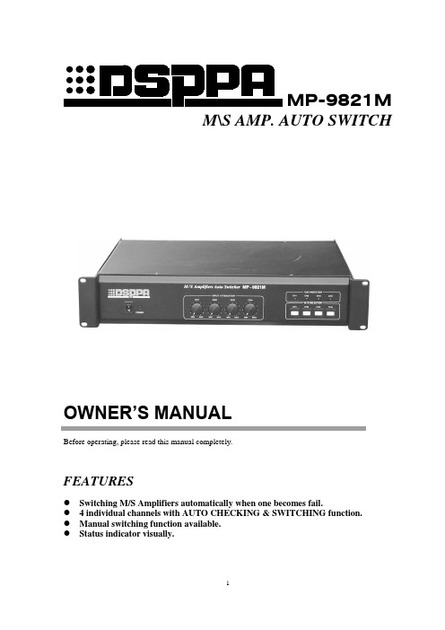
MP-9821MM\S AMP. AUTO SWITCHOWNER’S MANUALBefore operating, please read this manual completely.FEATURES●Switching M/S Amplifiers automatically when one becomes fail.● 4 individual channels with AUTO CHECKING & SWITCHING function.●Manual switching function available.●Status indicator visually.Left blank for memoFRONT PANEL① POWER SWITCH ③VOLUMES ⑤ S-AMP. (ALM) INDICATORS ② POWER INDICATOR ④ MANUAL BUTTONSREAR PANELCONNECTIONS ( CH. 1 for example )① SOURCE INPUT PORT ④ M-AMP. OUTPUT PORT ⑦ LINK ② M-AMP. INPUT PORT ⑤ S-AMP. OUTPUT PORT ⑧ FUSE③ S-AMP. INPUT PORT ⑥ SPEAKERS⑨ CORD① ② ③ ④⑤② ③ ④ ⑤ ⑥ ⑨ ⑧① ⑦SpeakersOPERATION1.Make connections correctly and turn on the main power of all the devises of the system together. 2.Put volumes of M-Amp. and S-Amp. clockwise to the end. Adjust volume of the system with the volumes on front panel of this module.3.The system will be reset automatically with M-Amp. on duty after turning on. Pressing down M\S selectors on the front panel will switch to S-Amp. Manually with the indicators lit.4.The system will be switching between M-Amp. and S-Amp. alternatively with alarming while they are failure.5.You can use only one S-Amp. as a spare set of 4 channels. In this case, sometimes the system may be overload and it is out of the warrantee of the manufacture.SPECIFICATIONSDSPPA ACOUSTIC TECHNOLOGY CO. LTD.MP-9821M主 \ 备功放自动切换器使用说明欢迎惠顾。
Soundstream 电源放大器说明书

two 4 ohm woofers in parallel = 2 ohms
two 4 ohm woofers in series = 8 ohms
SOUNDSTREAM TECHNOLOGIES
120 Blue Ravine Road Folsom California 95630 USA ph 916.351.1288 fax 916.351.0414 ver. 1.17.96a
TROUBLESHOOTING
PROBLEM
CAUSE
No sound and LED is not lit
Repeatedly blown amp fuse, frequent activation of Thermal Protection Circuit
• no power or ground at amp • no remote turn-on signal • blown fuse near battery • blown amp power supply fuse
tion
ห้องสมุดไป่ตู้
TABLE OF CONTENTS
USA•305 Diagram ....................................................... 4 - 5 Features........................................................................... 6 Crossover Modes ............................................................. 7 Crossover Adjustments .................................................... 8 Selecting Input Modes...................................................... 9 Wiring & Wiring Diagram......................................... 10 - 11 Installation and Mounting ............................................... 12 Level Setting .................................................................. 13 Sample Systems ..................................................... 14 - 17 Protection Circuitry & Troubleshooting ........................... 18 Service ........................................................................... 19 Specifications................................................................. 19
香Sizes(High Efficiency Power Amplifier)高效功率放大器用户手册
ii
Contents
Suggestions for Safety ................................................................................................ i Electrical Safety.............................................................................................................. i Transportation Safety ..................................................................................................... i Environmental Regulations ............................................................................................. i Safe Use Precautions ..................................................................................................... i Manual Labels and Information...................................................................................... ii