ASTM A897&A897M-2003 等温淬火球墨铸铁
ASTM A标准(中文)

AA1000-99 弹簧专用碳钢和合金钢钢丝规范A1001-99 大型材高强度钢铸件规范A1002-99 镍铝类合金铸件规范A100-93(2000) 硅铁A101-93(2000) 铬铁A102-93(2000) 钒铁合金A105/A105M-01 管系部件用碳素钢锻件A106-999e1 高温用无缝碳素钢管A108-99 优质冷加工碳素钢棒材技术规范A109/A109M-00e1 冷轧碳素钢带技术规范A111-99a 电话和电报线路用镀锌"铁"丝规格A116-00 镀锌钢丝编织栏栅网A121-99 镀锌刺钢丝A123/A123M-00 钢铁产品的锌镀层(热浸镀锌)技术规范A125-96 热处理螺旋形钢弹簧A126-95(2001) 阀门、法兰和管配件用灰铁铸件A128/A128M-93(1998) 钢铸件,奥氏体锰A131/A131M-94 海船用结构钢A132-89(2000) 钼铁合金A134-96 电熔(电弧)焊钢管(NPS为16英寸和16英寸以上)A135-01 电阻焊钢管A139-00 电熔(电弧)焊钢管(4英寸以上的)A143-74(1999) 热浸镀锌结构钢制品防脆裂措施和探测脆裂的程序A146-64(2000) 氧化钼制品A148/A148M-01 结构用高强度钢铸件A153/A153M-00 钢铁制金属构件上镀锌层(热浸)A159-83(2001) 汽车用灰铁铸件A167-99 不锈钢和耐热铬镍钢板、薄板及带材A176-99 不锈钢和耐热铬钢板、薄板及带材A178/A178M-95(2000) 电阻焊接碳素钢钢管及碳锰钢锅炉和过热器管的技术规范A179/A179M-90a(1996)e1 热交换器和冷凝器用无缝冷拉低碳钢管A181/A181M-01 普通锻制碳素钢管的规格A182/A182M-01 高温设备用锻制或轧制的合金钢管法兰、锻制管件、阀门及零件A183-98 钢轨用碳素钢螺栓和螺母A184/A184M-01 混凝土加筋用变形钢筋编织网A185-97 钢筋混凝土用焊接钢丝结构A1-00 碳素钢丁字轨A192/A192M-91(1996)e1 高压用无缝碳素钢锅炉管A193/A193M-01 高温设备用合金钢和不锈钢螺栓材料A194/A194M-01 高温和高压设备用碳素钢与合金钢螺栓和螺母的规格A197/A197M-00 化铁炉用可锻铸铁A20/A20M-01 压力容器用钢板材通用要求A202/A202M-93(1999) 压力容器用铬锰硅合金钢板A203/A203M-97 压力容器用镍合金钢板A204/A204M-93(1999) 压力容器用钼合金钢板A209/A209M-98 锅炉和过热器用无缝碳钼合金钢管A210/A210M-96 锅炉和过热器用无缝中碳素管A213/A213M-01 无缝铁素体和奥氏体合金钢锅炉、过热器和换热器管A214/A214M-96 热交换器与冷凝器用电阻焊接碳素钢管A216/A216M-93(1998) 高温下使用的适合于熔焊的碳素钢铸件规格A217/A217M-01 适合高温受压零件用合金钢和马氏体不锈钢铸件A21-94(1999) 铁路用未经热处理和经热处理的碳素钢轴A220/A220M-99 珠光体可锻铁A225/A225M-93(1999) 压力容器用锰矾镍合金钢板A227/A227M-99 机械弹簧用冷拉钢丝A228/A228M-00 乐器用优质弹簧钢丝A229/A229M-99 机械弹簧用油回火的钢丝A230/A230M-99 阀门用油回火优质碳素钢弹簧丝A231/A231M-96 铬钒合金钢弹簧丝A232/A232M-99 阀门用优质铬钒合金钢弹簧丝A234/A234M-00a 中温与高温下使用的锻制碳素钢及合金钢管配件A239-95(1999) 用普力斯试验法(硫酸铜浸蚀)确定铁或钢制品上镀锌层最薄点的测试方法A240/A240M-01 压力容器用耐热铬及铬镍不锈钢板、薄板及带材A242/A242M-00a 高强度低合金结构钢A247-67(1998) 铁铸件中石墨显微结构评定试验方法A249/A249M-01 锅炉、过热器、换热器和冷凝器用焊接奥氏体钢管A250/A250M-95(2001) 锅炉和过热器用电阻焊铁素体合金钢管A252-98e1 焊接钢和无缝钢管桩A254-97 铜焊钢管规格A255-99 测定钢淬透性用末端淬火试验的标准试验方法A262-98 奥氏体不锈钢晶间浸蚀敏感性的检测A263-94a(1999) 耐腐蚀铬钢包覆板材,薄板材及带材技术规范A264-94a(1999) 包覆的不锈铬镍钢板,薄板及带材规格A265-94a(1999) 镍和镍基合金包覆钢板规格A266/A266M-99 压力容器部件用碳素钢锻件规格A268/A268M-01 一般设备用无缝和焊接铁素体与马氏体不锈钢管A269-01 一般设备用无缝和焊接奥氏体不锈钢管A27/A27M-95(2000) 通用碳素钢铸件A270-01 卫生设施用无缝钢和焊接奥氏体不锈钢管A275/A275M-98 钢锻件的磁粉检查试验方法A276-00a 不锈钢棒材和型材A278-93 适用于650F容压部件用灰铸铁件的技术规范A283/A283M-00 低和中等抗拉强度碳素钢板A285/A285M-90(2001) 压力容器用低和中等抗拉强度的碳素钢板A288-91(1998) 涡轮发电机磁性定位环用碳素钢和合金钢锻件A289/A289M-97 发电机非磁性定位环用合金钢锻件的技术规范A29/A29M-99e1 热锻及冷加工碳素钢和合金钢棒A2-90(1997) 普通型,带槽和防护型碳素工字钢轨A290-95(1999) 减速器环用碳素钢和合金钢锻件A291-95(1999) 减速器小齿轮、齿轮和心轴用碳素钢和合金钢锻件A295-98 高碳耐磨轴承钢技术规范A297/A297M-97(1998) 一般用耐热铬铁与镍铬铁合金钢铸件规格A299/A299M-97e1 压力容器用锰硅碳钢板A302/A302M-97e1 压力容器用锰钼和锰钼镍合金钢板A304-96 有末端淬火淬透性要求的合金钢棒材的技术规范A307-00 抗拉强度为60000psi的碳素钢螺栓和螺柱的技术规范A308-99 经热浸处理镀有铅锡合金的薄板材的技术规范A309-94a(1999) 用三点试验法测定长镀锌薄钢板镀层的重量成分的试验方法A311/A311M-95(2000) 有机械性能要求的消除应力的冷拉碳素钢棒A312/A312M-00c 无缝和焊接奥氏体不锈钢管A313/A313M-98 不锈钢弹簧丝技术规范A314-97 锻造用不锈及耐热钢坯及钢棒规格A31-00 钢铆钉及铆钉和压力容器用棒材A319-71(2001) 高温无压部件用灰铁铸件A320/A320M-01 低温用合金钢螺栓材料规格A321-90(1995)e1 经淬火和回火的碳素钢棒A322-91(1996) 合金钢棒材.级别A323-93(2000) 硼铁规格A324-73(2000) 钛铁合金A325-00 经热处理最小抗拉强度为120/105ksi的钢结构螺栓A325M-00 结构钢连接件用高强度螺栓(米制)A327-91(1997) 铸铁冲击试验方法A327M-91(1997) 铸铁冲击试验方法(米制)A328/A328M-00 薄钢板桩A331-95(2000) 冷加工合金钢棒A333/A333M-99 低温用无缝与焊接钢管规格A334/A334M-99 低温设备用无缝与焊接碳素和合金钢管A335/A335M-01 高温用无缝铁素体合金钢管A336/A336M-99e1 压力与高温部件用合金钢锻件规格A338-84(1998) 铁路,船舶和其他重型装备在温度达到650华氏度(345摄氏度)时使用的可锻铸铁法兰,管件和阀门零件A34/A34M-96 磁性材料的抽样和采购试验的标准惯例A340-99a 有关磁性试验用符号和定义的术语A341/A341M-00 用直流磁导计和冲击试验法测定材料的直流磁性能的试验方法A342/A342M-99 磁铁材料导磁率的试验方法A343-97 在电力频率下用瓦特计-安培计-伏特计法(100-1000赫兹)和25 厘米艾普斯亭(EPSTEIN) 机架测定材料的交流电磁性能的试验方法A345-98 磁设备用平轧电炉钢A348/A348M-00 用瓦特计--安培计--伏特计法(100-10000赫兹)和25厘米艾普斯亭框测定材料的交流磁性能的试验方法A350/A350M-00c 要求进行缺口韧性试验的管道部件用碳素钢与低合金钢锻件技术规范A351/A351M-00 容压零件用奥氏体及奥氏体铁素体铸铁的技术规范A352/A352M-93(1998) 低温受压零件用铁素体和马氏体钢铸件规格A353/A353M-93(1999) 压力容器用经二次正火及回火处理的含9%镍的合金钢板A354-01 淬火与回火合金钢螺栓,双头螺栓及其他外螺纹紧固件规格A355-89(2000) 渗氮用合金钢棒A356/A356M-98e1 蒸汽轮机用厚壁碳素钢、低合金钢和不锈钢铸件A358/A358M-01 高温用电熔焊奥氏体铬镍合金钢管A36/A36M-00a 碳素结构钢技术规范A363-98 地面架空线用镀锌钢丝绳A367-60(1999) 铸铁的激冷试验方法A368-95a(2000) 不锈钢和耐热钢丝绳的标准A369/A369M-01 高温用锻制和镗孔碳素钢管和铁素体合金钢管A370-97a 钢制品机械测试的标准试验方法和定义A372/A372M-99 薄壁压力容器用碳素钢及合金钢锻件A376/A376M-01 高温中心站用无缝奥氏钢管A377-99 球墨铸铁压力管规范索引A380-99e1 不锈钢零件、设备和系统的清洗和除垢A381-96 高压输送用金属弧焊钢管A384-76(1996) 防止钢组件热浸镀锌时翘曲和扭曲用安全保护A385-00 提供高质量镀锌覆层(热浸)A3-01 低、中、高碳素钢鱼尾(连接)板A387/A387M-99e1 压力容器用铬钼合金钢板A388/A388M-95(2000)e1 重型钢锻件超声波检测A389/A389M-93(1998) 适合高温受压部件用经特殊热处理的合金钢铸件规格A390-95(2001) 饲养家禽用镀锌钢丝栏栅网(六角形和直线形)A391/A391M-98 80号合金钢链条A392-96 镀锌钢丝链环栏栅网A394-00 传动塔架用镀锌和裸露钢螺栓A395/A395M-99 高温用铁素体球墨铸铁受压铸件A400-69(2000) 钢棒的成分及机械性能选择指南A401/A401M-98 铬硅合金钢丝A403/A403M-00b 锻制奥氏体不锈钢管配件A407-93(1998) 盘簧用冷拉钢丝A409/A409M-01 腐蚀场所或高温下使用的焊接大口径奥氏体钢管A411-98 镀锌低碳钢铠装线A413/A413M-00 碳素钢链A414/A414M-00 压力容器用碳素薄钢板A416/A416M-99 预应力混凝土用无涂层七股钢铰线A417-93(1998) 之字型、方型和正弦型装垫弹簧元件用冷拉钢丝A418-99 涡轮机及发电机钢转子锻件的超声波检查方法A420/A420M-00b 低温下用锻制碳素钢和合金钢管配件A421/A421M-98a 预应力混凝土用无涂层消除应力钢丝的技术规范A423/A423M-95(2000) 无缝和电焊低合金钢管A424-00 搪瓷用钢薄板A426-92(1997) 高温用离心铸造的铁素体合金钢管A427-74(1996)e1 冷轧和热轧用锻制合金钢辊A428/A428M-01 钢铁制品上铝覆层重量的测试方法A434-90a(2000) 热轧与冷精轧经回火及淬火的合金钢棒A435/A435M-90(2001) 钢板的直射束纵向超声波检验A436-84(1997)e1 奥氏体灰口铁铸件A437/A437M-01 高温用经特殊处理的涡轮型合金钢螺栓材料A438-80(1997) 灰铸铁横向弯曲试验A439-83(1999) 奥氏体可锻铸铁铸件A447/A447M-93(1998) 高温用镍铬铁合金钢铸件(25-12级)A449-00 经淬火和回火的钢螺栓和螺柱A450/A450M-96a 碳素钢管、铁素体合金钢管及奥氏体合金钢管A451-93(1997) 高温用离心铸造的奥氏体钢管A453/A453M-00 具有同奥氏体钢相类似的膨胀系数、屈服强度为50-120Ksi(345-827MPa)的耐高温螺栓材料A455/A455M-90(2001) 压力容器用高强度碳锰钢板A456/A456M-99 大型曲轴锻件的磁粉检查A459-97 镀锌平轧扁钢铠装带A460-94(1999) 包铜钢丝绳标准A463/A463M-00 热浸镀铝薄钢板A466/A466M-98 非焊接碳素钢链A467/A467M-98 机器链和盘旋链A469-94a(1999) 用于发电机转子的真空处理钢锻件A470-01 涡轮机转子和轴用经真空处理的碳素钢和合金锻件A471-94(1999) 涡轮转子转盘和转轮用真空处理合金钢锻件技术规范A472-98 蒸汽涡轮机轴及转子锻件的热稳定性的试验方法A473-01 不锈和耐热钢锻件A474-98 包铝钢丝绳标准A475-98 镀锌钢丝绳A476/A476M-00 造纸厂干燥辊用球墨可锻铸铁件A478-97 铬镍不锈钢和耐热钢制编织钢丝A479/A479M-00 锅炉及压力容器用不锈钢和耐热钢棒与型材A47/A47M-99 铁素体可锻铁铸件A480/A480M-01 扁平轧制耐热不锈钢厚板材、薄板材和带材通用要求A481-94(2000) 金属铬A482-93(2000) 铬铁硅A483-64(2000) 硅锰合金A484/A484M-00 不锈及耐热锻钢棒,钢坯及锻件的规格A485-00 高淬透性耐磨轴承钢的技术规范A487/A487M-93(1998) 受压钢铸件A488/A488M-01 钢铸件焊接规程和工作人员的合格鉴定A48-94ae1 灰铁铸件A489-00 碳素钢吊耳A490-00 最小拉伸强度为150千磅/平方英寸热处理钢结构螺栓A491-96 镀铝钢链环栏栅结构A492-95(2000) 耐热不锈钢丝绳A493-95(2000) 冷镦和冷锻不锈钢和耐热钢丝A494/A494M-00 镍和镍合金铸件A495-94(2000) 硅钙合金钢技术规范A496-97ae1 钢筋混凝土用变形钢丝A497-99e1 钢筋混凝土用焊接变形钢丝网A498-98 无缝与焊接碳素钢,铁素体钢与奥氏体钢制有整体散热片的换热器钢管A49-01 经热处理的碳素钢鱼尾(连接)板,微合金鱼尾板及锻制碳素钢异型鱼尾板A499-89(1997)e1 轧制丁字钢轨用的碳素钢棒材及型材的技术规范A500-01 圆形与异型焊接与无缝碳素钢结构管A501-01 热成型焊接与无缝碳素钢结构管A503/A503M-01 锻制大型曲轴的超声波检验A504-93(1999) 锻制碳素钢轮A505-00 热轧和冷轧合金钢薄板和带材A506-00 正规质量及优质结构的热轧和冷轧合金钢薄板与带材A507-00 优质拉拔,热轧和冷轧合金钢薄板与带材A508/A508M-95(1999) 压力容器用经回火和淬火真空处理的碳素钢与合金钢锻件A510-00 碳素钢盘条和粗圆钢丝通用要求A510M-00 碳素钢盘条和粗圆钢丝(米制)A511-96 无缝不锈钢机械管A512-96 冷拉对缝焊碳素钢机械管A513-00 电阻焊碳素钢与合金钢机械钢管A514/A514M-00a 焊接用经回火与淬火的高屈服强度合金钢板A515/A515M-92(1997) 中温及高温压力容器用碳素钢板A516/A516M-90(2001) 中温及低温压力容器用碳素钢板A517/A517M-93(1999) 压力容器用经回火与淬火的高强度合金钢板A518/A518M-99 耐蚀高硅铁铸件A519-96 无缝碳素钢与合金钢机械管A521-96 一般工业用闭式模钢锻件A522/A522M-95b(2000) 低温用锻制或轧制含镍8%和9%的合金钢法兰,配件,阀门和零件规格A523-96 高压管型电缆线路用平端无缝与电阻焊钢管A524-96 常温和低温用无缝碳素钢管A529/A529M-00 高强度碳锰结构钢质量A530/A530M-99e1 特种碳素钢和合金钢管A531/A531M-91(1996) 涡轮发电机钢定位环的超声波检验A532/A532M-93a(1999)e1 耐磨铸铁A533/A533M-93(1999) 压力容器用经回火和淬火的锰钼及锰钼镍合金钢板A534-94 用于耐摩擦轴承的渗碳钢A536-84(1999)e1 球墨铸铁件A537/A537M-95(2000) 压力容器用经热处理的碳锰硅钢板A53/A53M-01 无镀层热浸的、镀锌的、焊接的及无缝钢管的技术规范A539-99 天然气和燃料油管线用电阻焊钢盘管A540/A540M-00 特殊用途的合金钢螺栓材料A541/A541M-95(1999) 压力容器部件用经淬火和回火的碳素钢及合金钢锻件A542/A542M-99e1 压力容器用经回火和淬火的铬钼、铬钼钒及铬钼钒钛硼合金钢板A543/A543M-93(1999) 压力容器用经回火和淬火的镍铬钼合金钢板A550-78(2000) 铌铁合金A551-94(1999) 钢轮箍A553/A553M-95(2000) 压力容器用经回火和淬火的含8%及9%镍的合金钢板A554-98e1 焊接的无缝钢机械管A555/A555M-97 耐热不锈钢丝和盘条的通用要求A556/A556M-96 无缝冷拉碳素钢给水加热器管A560/A560M-93(1998) 铬镍合金铸件A561-71(1999) 工具钢棒的宏观刻蚀试验A562/A562M-90(2001) 搪玻璃或扩散金属镀层的压力容器用锰钛合金碳素钢板A563-00 碳合金钢螺母A563M-00 碳素钢及合金钢螺母技术规范(米制)A564/A564M-01 热轧及冷精轧时效硬化处理过的不锈钢棒材和型材技术规范A565-97 高温用马氏体不锈钢棒,锻件和锻制坯规格A568/A568M-00b 热轧及冷轧高强度低合金碳素钢薄板A571-84(1997) 适用于低温压力容器零件的奥氏体球墨铸铁件A571M-84(1997) 适用于低温压力容器零件的奥氏体球墨铸铁件(米制)A572/A572M-00a 高强度低合金钴钒结构钢技术规范A573/A573M-00a 增强韧性的结构碳素钢板A574-00 合金钢内六角螺钉A574M-00 合金钢内六角螺钉(米制)A575-96 商品级碳素钢棒(M级)A576-90b(2000) 特级热轧碳素钢棒A577/A577M-90(2001) 钢板的超声角波束检验A578/A578M-96(2001) 特殊设备用的普通钢板和包覆钢板的直波束超声探伤检验A579-99 超高强度合金钢锻件A580/A580M-98 耐热不锈钢丝A581/A581M-95b(2000) 高速切削用耐热不锈钢丝和盘条A582/A582M-95b(2000) 热轧或冷精轧的高速切削不锈及耐热钢棒A583-93(1999) 铁路用铸钢轮A584-97 镀铝钢丝编织栅栏网A585-97 镀铝刺钢丝A586-98 镀锌平行和螺旋形钢丝绳A587-96 化学工业用电阻焊低碳钢管A588/A588M-00a 高强度低合金结构钢4英寸(100mm)厚屈服点最小为50ksi(345MPa) A589-96 水井用无缝和焊接碳素钢管A591/A591M-98 薄镀层电解镀锌薄钢板A592/A592M-89(1999) 压力容器用经回火和淬火的高强度低合金钢锻制附件和零件A595-98 结构用圆锥形低碳钢管A596/A596M-95(1999) 用环形试验法和冲击法测定材料的直流磁性能的试验方法A597-87(1999) 铸造工具钢A598-92(1997) 磁放大器磁芯的磁性能测试法A599/A599M-99 锡制品,电解镀锡的冷滚轧薄板规范A6/A6M-01 轧制结构钢板材、型材和薄板桩通用技术要求A600-92a(1999) 高速工具钢A601-96(2000) 电解金属锰A602-94(1998) 汽车用可锻铸铁件A603-98 镀锌结构钢丝绳A604-93(1998) 自耗电极再溶化钢棒与钢坯的宏观腐蚀试验方法A606-98 改进防大气腐蚀性的热轧和冷轧高强度低合金钢薄板和带材A608-91a(1998) 高温受压离心铸造的铁铬镍高合金钢管A609/A609M-91(1997) 碳素钢,低合金钢和马氏体不锈钢铸件的超声波检测A610-79(2000) 尺寸测量用铁合金的取样和试验A611-00 冷轧优质碳素结构钢薄板A612/A612M-00 中温和低温压力容器用高强度碳素钢板A615/A615M-01a 钢筋混凝土配筋用变形和光面坯钢筋A618-01 热成型焊接与无缝高强度低合金结构钢管系A623-00 锡轧制产品A623M-00 镀锡薄钢板轧制品通用要求(米制)A624/A624M-98 锡辊轧制品.单压延电解马口铁A625/625M-98 一次轧制原钢板(未镀)和镀锡薄钢板轧制产品技术规范A626/A626M-98 二次压延电解镀锡厚钢板轧制品技术规范A626/A626M-98 锡轧制品.二次压延的电解镀锡板(米制)A627-95 安全设备用均质不易加工的钢棒A629-88(1994)e1 安全设备用不易加工的扁钢棒和型材A630-98 热浸电解镀锡板镀锡层重量测定的方法A632-01 通用无缝和焊接奥氏体不锈钢管(小直径)A633/A633M-00a 正火的高强度低合金结构钢A635/A635M-00 热轧碳素钢薄板,带材和重型粗盘条规格A636-76(2000) 氧化镍烧结块A638/A638M-00 高温用沉积硬化铁基超级合金棒,锻件及锻坯料A640-97 8字型缆吊架用镀锌钢丝绳A641/A641M-98 镀锌(电镀)碳素钢丝技术规范A644-98 铁铸件的相关术语A645/A645M-99a 压力容器用经特殊热处理的5%镍合金钢板A646-95(1999) 飞机及航空器锻件用优质合金钢大方坯及坯段A648-95(2000) 预应力混凝土管用冷拉钢丝A649/A649M-99 波纹纸机械用锻制钢辊规格A650/A650M-98 二次压延的锡轧黑板材A653/A653M-00 热浸处理的镀锌铁合金或镀锌合金薄钢板的标准规范A656/A656M-00a 具有改良可模锻性的高强度低合金热轧结构钢板A657/A657M-98a 一次和二次压延电解镀铬黑钢板轧制品技术规范A65-01 钢轨道钉A659/A659M-97 商业级热轧碳素钢薄板和带材(最大含碳量为0.16%-0.25%) A660-96 高温用离心铸造碳素钢管A662/A662M-99 中温和低温压力容器用锰碳钢板规格A663/A663M-89(2000) 商品级碳素钢棒的机械特性A664-99 在ASTM规范中对电工钢和层压钢级别的识别A666-00 退火或冷加工的奥氏体不锈钢薄板、带材、中厚板和扁棒A667/A667M-87(1998) 离心铸造的双金属(灰口及白口铸铁)圆柱体A668/A668M-96e1 一般工业用碳素钢和合金钢锻件A66-01 钢质螺旋道钉A671-96 常温和较低温用电熔焊钢管A672-96 中温高压用电熔焊钢管A673/A673M-95 结构钢冲击试验的取样程序A674-00 水或其它液体用球墨铸铁管的聚乙烯包装A675/A675M-90a(2000) 专用热轧碳素钢棒的机械特性A677/A677M-99 全处理型无取向电工钢A678/A678M-00a 结构用经回火和淬火的高强度低合金碳素钢板规格A679/A679M-00 硬(冷)拉高抗拉强度钢丝A67-00 热加工低碳钢和高碳钢垫板技术规范A681-94(1999) 合金工具钢A682/A682M-00 弹簧用冷轧高碳钢带材A683/A683M-99 半处理型无取向电工钢A684/A684M-99 冷轧高碳钢带材A686-92(1999) 碳素工具钢A688/A688M-01 焊接的奥氏体不锈钢给水加热器管A689-97 弹簧用碳素钢及合金钢棒A690/A690M-00a 在海洋环境中使用的高强度低合金工字形钢桩和薄板桩规格A691-98 高温下高压装置用电熔焊碳素钢和合金钢管A693-93(1999) 沉淀硬化耐热不锈钢板、薄板和带材A694/A694M-00 高压传输设备用碳素钢及合金钢管法兰、配件、阀门及零件用锻件A695-90b(1995)e1 流体动力设备专用热锻碳素钢棒A696-90a(2000) 压力管道部件专用热锻或冷精轧碳素钢棒A697-98 用伏特计、安培计和瓦特计法测定迭层铁芯样品的交流磁特性的试验方法A698/A698M-92(1997)e1 在弱交流磁场中磁屏蔽效率的试验方法A700-99e1 钢制品国内装运的包装、标记和装载方法A701-96(2000) 硅锰铁A702-89(2000) 热锻钢栅栏柱和组件A703/A703M-01 受压部件用钢铸件A704/A704M-96 混凝土加筋用焊接普通钢棒或杆的光面钢筋或钢筋网A705/A705M-95(2000) 时效硬化的不锈和耐热钢锻件A706/A706M-01 混凝土配筋用变形低合金光面无节钢筋A707/A707M-00a 低温设备用锻制碳素钢和合金钢法兰A709/A709M-01 桥梁用结构钢A710/A710M-00 低碳时效硬化的镍铜铬钼铌合金钢A711-92(1996)e1 钢锻件坯料A712-97 软磁性合金电阻率的测试方法A713-93(1998) 热处理部件用高碳弹簧钢丝A714-99 高强度低合金焊接钢管和无缝钢管A716-99 球墨铸铁涵洞管A717/A717M-95 单片样品表面绝缘电阻率的试验方法A719-97 磁性材料的叠装系数的试验方法A720-97 无取向电工钢延展性的试验方法A721-97 取向的电工钢的延展性试验方法A722/A722M-98 预应力混凝土用无涂覆的高强度钢筋A723/A723M-94(1999) 高强度压力元件用合金钢锻件A724/A724M-99 叠层焊接的压力容器用经淬火及回火的碳素钢压力容器板A726-00 半成品型冷轧磁性迭片级钢A727/A727M-00 具有固定切口韧性的管道部件用碳素钢锻件A729-93(1999) 货物运输及电气铁路用热处理合金钢轴A730-93(1999) 铁路用碳素钢及合金钢锻件A732/A732M-98 一般设备用熔模铸造碳素低合金钢及高强度加温钴合金钢铸件A733-99 焊接及无缝碳素钢和奥氏体不锈钢管接头A734/A734M-87a(1997) 经淬火和回火的合金钢与高强度低合金钢压力容器板A735/A735M-99 中温和低温用低碳锰钼钶合金钢压力容器板A736/A736M-88(2000) 低碳时效硬化的镍铜铬钼铌和镍铜锰钼铌合金钢压力容器板A737/A737M-99 高强度低合金钢压力容器板A738/A738M-00 中温和低温设备用经热处理的碳锰硅钢压力容器板A739-90a(2000) 升温或/和加压部件用热轧合金钢棒A740-98 钢丝网(编织或焊接电镀钢丝网)A741-98 公路护栏用镀锌钢丝绳和配件A742/A742M-98 波纹钢管用预涂聚合物和金属涂覆钢薄板A743/A743M-98ae1 一般用耐腐蚀铬铁及镍铬铁合金铸件A744/A744M-00 严酷条件下使用的耐腐蚀镍铬铁合金铸件A745/A745M-94(1999) 奥氏体钢锻件的超声波检验A746-99 排污管用球墨铸铁A747/A747M-99 沉淀硬化不锈钢铸件A748/A748M-87(1998) 压力容器用静态铸造的激冷白口铁-灰口铁双金属轧辊A749/A749M-97 热轧碳素钢和高强度低合金钢带材通用要求A74-98 铸铁污水管及配件的技术规范A750-77(1994)e1 阻挡区域用钢制通风格栅A751-96 钢制品化学分析的实验方法、操作和术语A752-93(1998) 合金钢条和粗圆钢丝A752M-93(1998) 合金钢条和粗圆钢丝(米制)A753-97 镍铁软磁合金A754/A754M-96(2000) X射线荧光涂层厚度的试验方法A755/A755M-99 外露建筑材料用热浸涂覆和用卷涂工艺预涂的钢薄板A756-94(2001) 耐磨不锈轴承钢A757/A757M-00 低温下承压设备及其它设备用铁素体和马氏体钢铸件A758/A758M-00 具有改进的切口韧性的对缝焊锻制碳素钢管配件A759-00 起重机用碳钢轨条A760/A760M-01 下水道和排水沟用金属涂覆的波纹钢管A761/A761M-98 现场栓接管、管拱和拱用波纹镀锌结构钢板A762/A762M-00 下水道和排水沟用预涂聚合物波纹钢管A763-93(1999)e1 铁素体不锈钢晶间腐蚀敏感性检测A764-95(2001) 机械弹簧用冷拉镀锌和按成品尺寸镀锌的碳素钢丝A765/A765M-98a 具有强制性韧性要求的碳素钢及低合金钢压力容器部件锻件A767/A767M-00b 钢筋混凝土用镀锌钢筋A768-95 涡轮机转子及轴用经真空处理的含铬12%的合金钢锻件A769/A769M-00 电阻焊钢结构型材A770/A770M-86(2001) 专用钢板通过厚度测量进行的抗拉试验A771/A771M-95(2001) 增殖反应堆堆芯部件用奥氏体不锈钢管A772/A772M-00 正弦电流用材料的交流磁导率的试验方法A773/A773M-96 用带直流电子的磁滞曲线记录仪的(B-H)回路法测量材料的磁性能的标准试验方法A774/A774M-00 低温和中温一般腐蚀情况下用的焊接锻制奥氏体不锈钢配件A775/A775M-01 涂环氧树脂的钢筋钢棒A778-01 焊接未退火的奥氏体不锈钢管形制品A779/A779M-00 预应力混凝土用应力消除未涂覆的密实七股钢丝绞绳A780-01 热浸镀锌层的损坏及无覆层区域的检修A781/A781M-00 一般工业用一般要求的钢和合金铸件A782/A782M-90(2001) 经淬火和回火的锰铬钼硅锆合金钢压力容器板A786/A786M-00b 轧制钢楼板A787-01 电阻焊金属涂覆碳素钢机械配管A788-98a 钢锻件A789/A789M-01 普通设备用无缝与焊接铁素体/奥氏体不锈钢管A790/A790M-01 无缝与焊接铁素体/奥氏体不锈钢管A792/A792M-99 热浸工艺法处理的55%铝-锌合金涂覆钢板A793-96 不锈钢轧制楼板A794-97 商品级冷轧碳素钢薄板(最高含碳量为0.16%-0.25%)A795-00 防火用黑色及热浸镀锌的焊接和无缝钢管A796/A796M-00 雨水管和卫生污水管及其它地下埋设管道用波纹钢管、管托架及拱形架结构设计惯例A798/A798M-01 下水道及其它类似用途用工厂制波纹钢管的安装A799/A799M-92(1997) 估算不锈钢铸件铁素体含量用仪表的校准A800/A800M-01 奥氏体合金钢铸件中铁素体含量的估算A801/A801M-99 铁钴高磁性饱和合金A802/A802M-95(2001) 钢铸件外观检验的表面验收标准A803/A803M-01 焊接铁素体不锈钢给水加热器管A804/A804M-99 在电力频率下用薄钢板型试样对材料交流磁特性的测试方法A805-93(1998) 冷轧碳素钢扁平线A807/A807M-97 下水道及其它类似用途用波纹结构钢涂覆管的安装A808/A808M-00a 具有改进的切口韧性的结构级高强度低合金碳钢、锰钢、铌钢和钒钢A809-98 镀铝碳素钢丝A810-00 镀锌钢管用绕网A811-97 粉末冶金技术制造的软磁铁零件A813/A813M-01 单或双焊接奥氏体不锈钢管A814/A814M-01 冷加工焊接奥氏体不锈钢管A815/A815M-01 锻制铁素体、铁素体/奥氏体和马氏体不锈钢管配件A817-00 链接栅栏网用金属涂覆钢丝A818-91(2001) 镀铜碳素钢丝A820-96 纤维增强混凝土用钢纤维A821/A821M-99 预应力混凝土容器用经回火的冷拉钢丝A822-90(2000) 液压系统设备用冷拉碳素无缝钢管A823-99 静铸永久铸模灰铸件A824-01 链接栅栏用Marcelled拉力金属涂覆钢丝A826/A826M-95(2001) 增殖反应堆堆芯部件用奥氏体和铁素体不锈钢管A827/A827M-93a(1998) 锻造及类似用途用的碳素钢板技术规范A829/A829M-00 结构性合金钢板A82-97ae1 钢筋混凝土用无节钢丝A830/A830M-00 按照化学成分要求提供的优质碳素钢板技术规范A831/A831M-95(2000) 核心部件用不锈耐热钢棒,坯段及锻件规格A832/A832M-99e1 压力容器板用铬钼钒及铬钼钒钛硼合金钢A833-84(1996) 用比较硬度测试仪测量金属材料的压痕硬性A834-95(2001) 一般工业用铁铸件的一般要求A835-84(2000) 铁合金与合金添加剂的筛分粒度A836/A836M-95b(2001) 搪瓷管和压力容器设备用钛稳定碳素体钢锻件A837-91(1996)e1 渗碳用合金钢锻件A838/A838M-97 继电器用易切削铁素体不锈软磁合金技术规范A839/A839M-96 软磁用途的磷铁粉末冶金制造的零件技术规范A840/A840M-00 全处理的磁性夹层钢A841/A841M-01 压力容器用温度机械控制工艺加工的钢板A842-85(1997) 高密度石墨铸铁A844/A844M-93(1999) 压力容器用直接淬火加工的含镍9%的合金钢板A845-85(2000) 用于脱氧与合金钢的钛碎片A846-85(2000) 用于脱氧与合金钢的铝碎片A847-99a 具有增强耐大气腐蚀性能的冷成型焊接与无缝高强度低合金结构管A848/A848M-96 低碳磁铁A849-00 波纹钢排水管和污水管用后涂覆铺面和衬里材料A851-96 高频感应焊接的未退火奥氏体钢冷凝器管A852/A852M-00a 最小屈服强度为70Ksi(485MPa),厚度为4英寸(100mm)的经淬火和回火的低合金结构钢板A853-93(1998) 普通碳素钢丝A854/A854M-98 镀锌高强度钢栅栏和格架用光滑金属线A855/A855M-98 锌-5%铝-铈合金涂覆的钢丝绳A856/A856M-98 锌-5%铝-铈合金涂覆的碳素钢丝A857/A857M-00a 冷成形轻型薄钢板桩A858/A858M-00 低温和腐蚀情况下用热处理碳素钢配件A859/A859M-95(1999) 压力容器部件用时效硬化镍铜铬钼钶低碳合金钢锻件A860/A860M-00 锻制高强度低合金钢的高强度对缝焊接配件A861-94e1 高硅铁管和配件A862/A862M-98 波纹钢污水管和排水管沥清(柏油)涂层的应用A865-97 钢管连接用黑色或镀锌焊接或无缝钢螺纹接头A866-94 耐磨中碳轴承钢A867/A867M-94(1998)e1 继电器用铁硅钢A871/A871M-00a 抗空气腐蚀的高强度低合金结构钢板。
ASTM A789A789M 通用无缝与焊接铁素体奥氏体不锈钢管
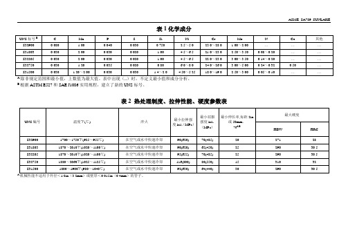
ASME SA789 SUNLAKE表1化学成分除非规定范围和最小值,上数值为最大值。
表中出现(..)时,不定义最小值和成分分析。
B根据ASTM E527和SAE J1086实用规程,建立了新的UNS标号。
表2 热处理制度、拉伸性能、硬度参数表A机械性能不适用于外径<1/8in(3.2mm)或壁厚<0.015in(0.4mm)的管子。
ASME SA789 SUNLAKE 尺寸要求:1、外径、壁厚和长度尺寸允许偏差见下表:A 订货的管子当壁厚大于等于3/4in.(19mm),或内径小于等于60%外径时,要求在壁厚是上有较宽的偏差范围,在这种规格中允许有±12.5%的壁厚偏差。
对于外径小于1/2in.(12.7mm),由于轧制时芯子不能顺利地拔出,故壁厚可以在规定值的±15%内变化。
B这些偏差适用于切割长度小于等于24ft(7.3m),对超过24ft(7.3m)长度的管子,每10ft(3m)或其不足部分允许额外加1/8in.(3mm),最大值为1/2in.(13mm)。
2、直度和表面质量成品钢管须有合理的直度,管端平滑无毛刺,且有良好的表面。
表面缺陷(指钢管中发现的任何不连续性和不规则性)可以用打磨法修除,但应保持圆滑的曲面,修后的壁厚不得小于本标准或产品标准允许的值。
修磨点外径可因修磨而减少。
检验项目:1、化学成分:满足表1的参数要求;2、尺寸要求;3、室温力学性能:满足表2的参数要求;4、硬度:满足表2的参数要求;5、扩口试验(对无缝钢管);6、卷边试验(对焊接钢管);7、反向压扁试验(对焊接钢管);8、水压试验或无损电测试验。
协议项目:1、水下空气压力试验。
ASTM A897&A897M-2003 等温淬火球墨铸铁
Designation:A897/A897M–03Standard Specification forAustempered Ductile Iron Castings1This standard is issued under thefixed designation A897/A897M;the number immediately following the designation indicates the year of original adoption or,in the case of revision,the year of last revision.A number in parentheses indicates the year of last reapproval.A superscript epsilon(e)indicates an editorial change since the last revision or reapproval.1.Scope1.1This specification covers ductile iron castings that are subsequently heat treated by an austempering process as defined in10.1.1.2The application of the austempering heat treatment extends the range of properties achievable in ductile iron castings.1.3No precise quantitative relationship can be stated be-tween the properties of the iron in various locations of the same casting or between the properties of castings and those of a test specimen cast from the same iron(see Appendix X1).How-ever,austempering heat treatment will tend to diminish any differences in mechanical properties.1.4The production of castings,machining(if required),and the austempering heat treatments may be performed by differ-ent manufacturers,as covered in Section15.The purchaser should establish by contract agreement,at the time of ordering, the responsibility of the various parties for meeting the specification requirements.1.5The values stated in either inch-pound or SI units are to be regarded separately as standard.Within the text,the SI units are shown in brackets[].The values stated in each system are not exact equivalents;therefore,each system shall be used independently of the bining values from the two systems may result in nonconformance with the specification.2.Referenced Documents2.1ASTM Standards:2A247Test Method for Evaluating the Microstructure of Graphite in Iron CastingsA370Test Methods and Definitions for Mechanical Testing of Steel ProductsA732Specification for Castings,Investment,Carbon and Low Alloy Steel for General Application,and Cobalt Alloyfor High Strength at Elevated TemperaturesA834Specification for Common Requirements for Iron Castings for General Industrial UseE8Test Methods for Tension Testing of Metallic Materials E10Test Methods for Brinell Hardness of Metallic Mate-rialsE23Test Methods for Notched Bar Impact Testing of Metallic Materials2.2Military Standard:MIL-STD-129Marking for Shipment and Storage33.Ordering Information3.1Orders for material to this specification shall include the following information:3.1.1ASTM designation,with year of issue,3.1.2Grade of austempered ductile iron required(see Table 1and Sections6and7),3.1.3Chemical composition requirements,if any(see Sec-tion4),3.1.4Heat treated microstructure restrictions(see Section 10),3.1.5Test coupon criteria(see Section12),3.1.6Lot size and tests per lot(see12.6and Section15), 3.1.7Special requirements,if desired,including hardness, radiographic soundness,magnetic particle inspection,pressure tightness,dimensions,or surfacefinish(see Section9),3.1.8Certification,if required(see Section16),3.1.9Special preparation for delivery,if required(see Sec-tion17).4.Chemical Composition4.1Although this specification has no specific chemical requirements,such requirements may be agreed upon between the manufacturer,heat treater,and the purchaser.5.Microstructure5.1The graphite component of the microstructure shall consist of a minimum80%spheroidal graphite conforming to Types I and II per Test Method A247.1This specification is under the jurisdiction of ASTM Committee A04on Iron Castings and is the direct responsibility of Subcommittee A04.02on Malleable and Ductile Iron Castings.Current edition approved Dec.1,2003.Published January2004.Originally approved st previous edition approved in2002as A897-02.2For referenced ASTM standards,visit the ASTM website,,or contact ASTM Customer Service at service@.For Annual Book of ASTMStandards volume information,refer to the standard’s Document Summary page on the ASTM website.3Available from Standardization Documents,Order Desk,Building4,Section D, 700Robbins Ave.,Philadelphia,PA19111-5098,Attn:NPODS.1Copyright©ASTM International,100Barr Harbor Drive,PO Box C700,West Conshohocken,PA19428-2959,UnitedStates.5.2The matrix microstructure shall substantially consist of ausferrite (acicular ferrite and high carbon,stable austenite).5.3The cooling rate within some sections may not be sufficient to avoid the formation of pearlite or other high temperature transformation products.In some cases,the maxi-mum acceptable quantities of these microconstituents and the location(s)within the casting may be established by agreement between the manufacturer,heat treater,and the purchaser.5.4Martensite may be present in minor amounts in the microstructures of Grades 200/155/02[1400/1100/02]and 230/185/01[1600/1300/01].Acceptable quantities of marten-site may be established by agreement between the manufac-turer,heat treater,and the purchaser.5.5The microstructure shall be substantially free of unde-sirable microconstituents,the details of which shall be agreed upon by the manufacturer,heat treater,and the purchaser.5.6The manufacturer,heat treater,and the purchaser may agree upon special chemical compositions or processing re-quirements to limit the microconstituents described in 5.3,5.4,and 5.5.6.Mechanical Properties6.1Tensile property requirements include tensile strength,yield strength,and elongation and apply only after austemper-ing heat treatment.6.2The iron represented by the test specimens shall con-form to the requirements as presented in Table 1.6.3The yield strength shall be determined by the 0.2%offset method (see Test Methods E 8).7.Impact Requirements7.1The iron represented by the test specimens shall con-form to the impact properties presented in Table 1.7.2Impact energy requirements apply only after test mate-rial has been austempered.The impact test specimens must be finish ground to required dimensions after heat treatment.8.Hardness8.1The area or areas on the castings where hardness is to be checked shall be established by agreement between the manu-facturer and purchaser,or the manufacturer and the end user.8.2Brinell hardness shall be determined according to Test Method E 10after sufficient material has been removed from the casting surface to insure representative hardness readings.The 10mm ball and 3000kg load shall be used unless otherwise specified and agreed upon.9.Special Requirements9.1When specified in the contract or purchase order,castings shall meet special requirements as to hardness,chemi-cal composition,microstructure,pressure tightness,radio-graphic soundness,magnetic particle inspection,dimensions,and surface finish.Refer to Specification A 834for a list of common requirements for iron castings not specifically refer-enced elsewhere in this specification.9.2When specified in the contract or purchase order,castings shall meet special requirements prior to the austem-pering heat treatment operation.10.Heat Treatment10.1Castings produced in accordance with this specifica-tion shall be heat treated by an austempering process consisting of heating the castings to a fully austenitic,homogeneous condition,cooling (at a rate usually sufficient to avoid the formation of pearlite)to a temperature above the martensite start temperature,and isothermally transforming the matrix structure for a time sufficient to produce the desired properties.This process shall produce a microstructure that is substantially ausferrite.10.2Upon agreement between the manufacturer and the purchaser,tension test specimens described in Section 13may be machined prior to the austempering heat treatment.In this case,heat treatment shall be performed in an inert or carbon controlled environment so as to prevent carburization,decar-burization,or scaling.Handling and fixturing must be such as to prevent test bar distortion (see X1.4).10.3Re-austempering of castings or any deviation from the established heat treating process is only permissable with the approval of the casting purchaser.TABLE 1Mechanical Property Requirements of GradesInch-pound unitsGrade 130/90/09Grade 150/110/07Grade 175/125/04Grade 200/155/02Grade 230/185/01Tensile strength,min,ksi 130150175200230Yield strength,min,ksi 90110125155185Elongation in 2in.,min,%97421Impact energy,ft-lb A7560452515Typical hardness,HBW,kg/mm 2269–341302–375341–444388–477402–512AUnnotched charpy bars tested at 7267°F.The values in the table are a minimum for the average of the highest three test values of the four tested samples.SI unitsGrade 900/650/09Grade 1050/750/07Grade 1200/850/04Grade 1400/1100/02Grade 1600/1300/01Tensile strength,min,MPa 9001050120014001600Yield strength,min,MPa 65075085011001300Elongation in 50mm,min,%97421Impact energy,J A10080603520Typical hardness,HBW,kg/mm 2269–341302–375341–444388–477402–512AUnnotched charpy bars tested at 2264°C.The values in the table are a minimum for the average of the highest three test values of the four testedsamples.11.Workmanship,Finish,and Appearance11.1The surfaces of castings shall be clean and free of adhering molding material,heat treatment oils or salts,cracks,hot tears,or other injurious defects such as slag and surface porosity.Dimensions shall conform to drawings or patterns supplied by the purchaser.11.2Castings shall not have chilled corners or center chill in areas to be machined.11.3Welding repair is not acceptable on austempered cast-ings.12.Test Coupons12.1Separately cast test coupons from which the tension test and Charpy test specimens are machined shall be cast to the size and shape shown in Fig.1or Fig.2.A modified keel block cast from the mold shown in Fig.3may be substituted for the 1-in.[25-mm]Y-block or the 1-in.[25-mm]keel block.The test coupons shall be cast in open molds made of suitable core sand having a minimum wall thickness of 11⁄2in.[38-mm]for the 1⁄2-in.[13-mm]and 1-in.[25-mm]sizes and 3in.[76-mm]for the 3-in.[76-mm]size.The coupons shall be left in the mold until they have cooled to a black color (900°F [480°C]or less).The size and type of coupon cast to represent the casting shall be at the option of the purchaser.In case no option is expressed,the manufacturer shall make the choice.12.2When investment castings are made in accordance with this specification,the manufacturer may use cast-to-size test specimens that are either incorporated in the mold with the castings or separately cast using the same type of mold and the same thermal conditions that are used to produce the castings.The test specimens shall be made to the dimensions shown in Fig.1of Specification A 732or Fig.5of Test Methods and Definitions A 370.The exact procedure to be used for produc-ing test specimens shall be agreed upon by the manufacturer and the purchaser.12.3When castings made in accordance with this specifi-cation are produced by nodularization directly in the mold,the manufacturer may use either separately cast test coupons or test specimens cut from castings.If test bars are to be cut from castings,test bar location shall be agreed upon by the purchaser and the manufacturer and indicated on the casting drawing.When separately cast test coupons are used,selection shall be as outlined in 12.1and shown in Figs.1-6.Appendix X2provides guidelines for selection of coupons with mold cooling rates representative of various casting sections.12.4Test coupons shall be poured from the same ladle or heat as the castings they represent and,unless otherwise agreed upon by the manufacturer and the purchaser,shall be subject to the same post inoculation and alloying practice.12.5Test coupons shall be heat treated with the castings they represent.12.6The number of test coupons and the number of tests required per order or lot size shall be established at the time of ordering.This agreement should include a definition of lot size.Lot size can be defined to include the entire order,a specified portion of that order,a specified manufacturing production period,or a specified quantity of parts shipped to the purchaser.12.7If any test specimen shows obvious defects,another may be cut from the same test block or from another test block representing the same metal.Positions other than “A”or “B”in Fig.4shall not be used.In those cases where removal of test bars from actual castings has been agreed upon (see 12.2and 12.3),a second test bar may be obtained from an alternate location of equivalent section or from a second casting processed in the samelot.13.Tension Test Specimens13.1The standard round tension test specimen with a 2-in.[50-mm]gage length shown in Fig.5shall be used,except when the 1⁄2-in.[13-mm]Y-block coupon is used.In this case,either of the test specimens shown in Fig.6shall be satisfac-tory.Tension test specimens shall be machined only from Positions A (preferred)or B in Fig.4.The test bars may be machined before or after heat treatment in accordance with 10.2.14.Impact Test Specimens14.1The unnotched Charpy impact strength shall be deter-mined according to Test Methods E 23with the following variations:Specimens are to be prepared unnotched to dimen-sions in Fig.9of Test Methods E 23.Blanks from which test specimens are machined shall be cut only from Positions A or B in Fig.4.Test temperature shall be 7267°F [2264°C].Four specimens shall be tested,with the lowest impact energy value discarded and the remaining three values averaged.The average impact energy shall meet the requirement of Table 1.15.Responsibility for Quality and Inspection15.1At the time of an order,the purchaser should establish an agreement for quality and inspection requirements with themanufacturers.The form of this agreement depends upon which of the conditions in 15.2or 15.3are determined to exist.15.2If all manufacturing operations are performed by a single manufacturer,that manufacturer is responsible for per-formance of all quality and inspection requirements covered herein.15.3If,at the time of ordering,the purchaser determines that more than one manufacturer will contribute to the casting,machining,and heat treatment operations,in any sequential fashion,an agreement should be negotiated that defines and assigns individual responsibility for each specific quality and inspection requirement.This does not prevent an agreement wherein any one manufacturer in the chain of sequential operations can agree to assume full responsibility for all quality and inspection requirements.15.4To avoid future disputes,the purchaser can require that all companies in the manufacturing chain be identified.Changes shall not be made without approval of the purchaser.The manufacturer(s)may require the purchaser to provide written agreement for any changes mutually agreed upon.15.5Unless specified to the contrary by the purchaser,any of the manufacturers in the chain may use his or her own or any other facilities for performance of the inspection requirements.Responsibility for meeting the specified properties remainsFIG.3Mold for Modified KeelBlock4with the parties defined in 15.2or 15.3.This shall not prevent the purchaser from also performing any or all of the quality and inspection requirements.16.Certification16.1Where required by contract,the manufacturer’s certi-fication shall be furnished to the purchaser stating that the material was manufactured,sampled,tested,and inspected in accordance with the material specification and was found tomeet the requirements.The certification shall include the results of all tests performed.17.Preparation for Delivery17.1Unless otherwise specified in the contract or purchase order,cleaning,drying,preservation,and packaging of castings shall be in accordance with the manufacturer’s commercial practice.Packaging and marking shall be adequate to ensure safe delivery by the carrier.FIG.4Sectioning Procedure for Y-BlocksFIG.5Standard Round Tension Test Specimen with 2-in.[50-mm]GageLength517.2Government Procurement—When specified in the con-tract or purchase order,marking for shipment shall be inaccordance with the requirements of MIL-STD-129.APPENDIXES(Nonmandatory Information)X1.MECHANICAL PROPERTIES OF CASTINGSX1.1In order to achieve the required mechanical properties in castings,or test coupons,the iron must have a chemical composition that provides sufficient hardenability to fully respond in the austempering heat treatment cycle.The response to heat treatment is affected by the effective section size, graphite nodule count,and chemical composition.It also depends on the capabilities of the specific heat treater’s equipment.The heavier the effective section size and the more massive the casting,the slower will be the cooling or quench-ing rate in the austempering cycle.This quenching rate must exceed some critical value to attain the correct microstructure (high carbon austenite plus acicular ferrite).X1.2Published literature and commercial heat treaters as well as many foundries can provide information on required alloy additions needed for specific parts,casting section sizes, or masses.Austempered Ductile Iron can be successfully produced from ductile iron castings with a wide range of chemical compositions and configurations.There is no opti-mum recipe;however those produced to the following param-eters have been shown to yield excellent results.X1.2.1The castings should be free of non-metallic inclu-sions,carbides,shrink and dross.Proper purchasing,storage and use of charge materials will minimize the occurrence of carbides and gas defects.Proper molding control will minimize surface defects and other sub-surface discontinuities.The castings should be properly gated and poured using consistent and effective treatment and inoculation techniques to yield shrink free castings.Any of the aforementioned non-conforming conditions will reduce the toughness of an ADI component,even if adequate for conventional ductile iron.The following should be met as a minimum:Nodule Count100/ mm2and Nodularity80%.X1.2.2The carbon equivalent(CE)can be approximated by the relationship:CE=%C+1/3(%Si).It should be controlled as follows in Table X1.1.X1.3Alloying elements such as Molybdenum,Copper, Nickel and additional Manganese above the base metal level should be added only when additional hardenability is required for heavy sections.Increased hardenability is only required to avoid the formation of pearlite during quenching.The amount of alloying required(if any)will be a function of thealloycontent in the base metal,the part configuration and the austempering process used.The proper alloy composition should be determined jointly by the foundry and the heat treating source.Addition of alloying elements when not re-quired does not enchance the properties of ADI and merely adds to the cost of the position guidelines are recommended in Table X1.2and Table X1.3.X1.3.1Other nodulizing elements like beryllium,calcium, strontium,barium,yttrium,lanthanum and cerium should be present only to the extent that they are used to replace Mg in treatment.The amount of residual Mg plus the amounts of these elements should not exceed0.06%.Carbide forming elements(like Cr,Ti,V)tend to be additive in effect with Mn and/or Mo;thus,one should take note of this in alloy design to avoid the formation of carbides in the casting.X1.3.2The preceding guidelines are intended to be useful parameters for production.Good ADI can,and is,being produced from ductile iron not meeting these criteria,however,TABLE X1.1Suggested Carbon Equivalent Ranges for VariousSection SizesSection Size CE Range0to1⁄2in.(0to13mm) 4.4to4.61⁄2to2in.(13to51mm) 4.3to4.6Over2in.(51mm) 4.3to4.5TABLE X1.2Suggested Targets and Control Ranges for Intentionally Added ElementsElement Recommended RangeCarbonCarbon should be controlled within the recommended range exceptwhen deviations are required to produce a defect-free casting.If toohigh levels of carbon are present,carbonflotation can occur andreduce the apparent strength levels of ADI.3.60%60.20%SiliconSilicon is one of the most important elements in ADI because itpromotes graphite formation,decreases the solubility of carbon inaustenite,increases the eutectoid temperature and inhibits theformation of bainitic carbide.Excessively high levels of Si cansuppress ausferrite in localized areas by stabilizing ferrite.2.50%60.20%MagnesiumMagnesium is added to create the conditions for graphite nodules toform.Excessively high levels will promote carbide formation whilelow levels promote nonspheroidal graphite.(%S x0.76)+0.025%60.005%ManganeseManganese additions above that of the base metal composition arenot recommended because Mn segregates to the last to freezeregions of the casting and will retard the formation of ausferrite if thenodule count is not sufficiently high to break up the Mn segregatedregion.In section sizes up to1⁄2in.or13mm,Mn targets as high as0.60%have been used due to high nodule counts.In section sizesover1⁄2in.(13mm)or in the presence of Mo other carbide formers,the Mn target should be reduced to0.35%or less to minimize theformation of cell boundary carbides which may negatively affectcomponent machinability or ductility,or both.0.35%60.05%CopperCopper may be added to ADI to increase hardenability in additionsup to0.80%.Above this level,Cu creates a diffusion barrier aroundthe graphite nodules,thus inhibiting carbon mobility duringaustenitizing.0.80%maximum,only as needed60.05%NickelNickel may be used to increase the hardenability of ductile iron inadditions up to2.0%.Because of the costs associated with the useof Ni,larger additions may be cost prohibitive.2.0%maximum,only as needed60.10%MolybdenumMolybdenum is the most potent hardenability agent in ADI and may be necessary in heavy section castings to prevent the formation of pearlite.Both tensile strength and ductility decrease as the Mo content increases beyond that required for hardenability.This deterioration in properties is likely caused by the segregation of Mo to cell boundaries and the formation of carbides.The level of Mo should be restricted to not more than0.30%in heavy section castings.0.30%maximum(only as needed)60.03%these criteria represent sound,commercial practices known to produce good results.They do not constitute a guarantee of final properties.X1.4Machining of tension test specimens after austemper-ing may be difficult,particularly for the higher strength grades.For this reason,some manufacturers prefer to machine the test bars to size or near net size (with some final grinding allowances)before the austempering operation.(Warning—Achieving the required mechanical properties and austempered microstructure in the smaller cross sections of a premachinedtest bar does not ensure the correct response in the heavier sections of actual parts,as explained in X1.1.When prema-chined test bars are to be used,it is recommended that adequate austempering be verified.This can be done by sectioning a casting,examining the microstructure in that section,and then comparing the results with that of a premachined test bar that has been austempered in the same furnace load.When inad-equate austempering response is identified,increased alloying as discussed in X1.3may be required.)X2.Y-BLOCK SELECTIONX2.1Table X2.1provides guidelines for the selection of Y-blocks that have cooling rates that are representative of equivalent shapes having the dimensions shown.ASTM International takes no position respecting the validity of any patent rights asserted in connection with any item mentioned in this ers of this standard are expressly advised that determination of the validity of any such patent rights,and the risk of infringement of such rights,are entirely their own responsibility.This standard is subject to revision at any time by the responsible technical committee and must be reviewed every five years and if not revised,either reapproved or withdrawn.Your comments are invited either for revision of this standard or for additional standards and should be addressed to ASTM International Headquarters.Your comments will receive careful consideration at a meeting of the responsible technical committee,which you may attend.If you feel that your comments have not received a fair hearing you should make your views known to the ASTM Committee on Standards,at the address shown below.This standard is copyrighted by ASTM International,100Barr Harbor Drive,PO Box C700,West Conshohocken,PA 19428-2959,United States.Individual reprints (single or multiple copies)of this standard may be obtained by contacting ASTM at the above address or at 610-832-9585(phone),610-832-9555(fax),or service@ (e-mail);or through the ASTM website ().TABLE X1.3Suggested Targets and Control Ranges for Trace or Tramp ElementsTrace or Tramp ElementsSuggested Target (or maximum)Typical Control RangeSn Tin 0.02%maximum 60.003%Sb Antimony 0.002%maximum 60.0003%P Phosphorus 0.04%maximum S Sulfur 0.02%maximum O Oxygen 50ppm maximum Cr Chromium 0.10%maximum Ti Titanium 0.040%maximum V Vanadium 0.10%maximum Al Aluminium 0.050%maximum As Arsenic 0.020%maximum Bi Bismuth 0.002%maximum B Boron 0.0004%maximum Cd Cadmium 0.005%maximum Pb Lead 0.002%maximum Se Selenium 0.030%maximum Te Tellurium0.003%maximumTABLE X2.1Equivalent Geometric Shapes Corresponding to Y-Blocks AY-BlockSize,in.[mm]Infinite Plate Thickness,in.[mm]Round Diameter,in.[mm]Cube Edge,in.[mm]0.5[13]0.5[13] 1.2[30] 1.8[46]1.0[25]0.9[22] 1.8[46] 2.8[72]3.0[76]1.6[40]3.1[80]4.8[120]AFor castings with cross sections that would require a Y-block greater than 3in.[76mm],alloy requirements must be based upon experimental trials with test castings or previous experience with similar parts.Test coupons should be selected upon agreement between the producer and thepurchaser.。
美标球化退火标准

美标球化退火标准
美标球化退火标准是指美国材料试验协会(ASTM)制定的一项钢材球化退火的标准。
该标准分为两个部分:ASTM A 897/A 897M 和ASTM A 1077/A 1077M。
其中,ASTM A 897/A 897M是一项强制性标准,规定了钢材球化退火要求的化学成分、热处理、力学性能以及检验方法。
该标准适用于无缝钢管、焊接钢管、冷轧钢板和冷轧钢带等各种球化退火钢材的生产和检验。
而ASTM A 1077/A 1077M则是一项推荐性标准,对于一些特殊用途的球化退火钢材,这个标准提供了更为详细的要求和检验方法。
同时,该标准还规定了一些细分的钢材等级,以满足不同用户对钢材的不同需求。
总的来说,美标球化退火标准对于保证钢材的质量和性能,以及确保钢材生产和使用的安全性具有重要意义。
铸件硬度检测方法
铸件的硬度检测铸造业是机械行业的一个重要分支,由于石墨的存在赋予铸铁优良的铸造性能、切削加工性能、减磨性能、减振性能以及低的缺口敏感性。
而且铸造生产设备简单, 制造成本低,因而在工业生产中得到广泛应用。
在各类机械产品中,按质量计算,铸件所占比例高达50%以上。
铸造件第一位的质量指标就是力学性能,测试工件力学性能的方法主要有两个,其一是拉伸试验,其二是硬度试验。
拉伸试验测试的是工件的抗拉强度,屈服强度和伸长率,而硬度试验反映的是在各自规定的条件下材料弹性、塑性、强度、韧性及磨损抗力等多种物理量的综合性能。
在美国铸件标准中几乎每一种产品都规定了拉伸试验。
多数产品规定了硬度试验。
拉伸试验设备复杂,投资较高,需要专业人员,需要制备试样,试验效率低,成本高。
硬度试验设备简单,易于掌握,压痕很小,可视为无损检测,可直接测试成品或半成品工件。
硬度试验测试效率高,可用于对成批工件的逐件检测。
随着硬度计制造技术的进步,各种便携式仪器,特别是高精度便携式仪器不断出现,使得硬度测试实现了简单、快捷和精确。
使现场硬度检测,生产线上的硬度控制及大工件的精确硬度检测成为可能。
硬度试验和拉伸试验基本上都是检测金属抵抗塑性变形的能力。
两种试验在某种程度上是检测金属相似的特性。
二者的试验结果是完全可以相互比较的,对于多数金属材料,硬度值和抗拉强度值是可以通过查表相互换算的。
因此在测试材料力学性能时,人们越来越多地选择采用硬度试验,而较少选用拉伸试验。
作者研究整理了美国标准ASTM中关于铸件硬度要求的规定。
本文主要有两部分内容,第一,美国标准ASTM中典型铸造产品关于硬度要求方面的规定。
第二,在铸造产品检测中硬度计的选用方法。
一、美国标准ASTM中关于铸件硬度的要求1、灰口铁铸件(ASTM A48-92)适用于主要考虑抗拉强度的一般工程用灰口铁铸件,铸件根据不同铸造试棒的抗拉强度分级。
在此类铸铁件中,化学成分相对于抗拉强度来说是次要的。
ASTM A789A789M 通用无缝与焊接铁素体奥氏体不锈钢管
ASME SA789 SUNLAKE表1化学成分除非规定范围和最小值,上数值为最大值。
表中出现(..)时,不定义最小值和成分分析。
B根据ASTM E527和SAE J1086实用规程,建立了新的UNS标号。
表2 热处理制度、拉伸性能、硬度参数表A机械性能不适用于外径<1/8in(3.2mm)或壁厚<0.015in(0.4mm)的管子。
ASME SA789 SUNLAKE 尺寸要求:1、外径、壁厚和长度尺寸允许偏差见下表:A 订货的管子当壁厚大于等于3/4in.(19mm),或内径小于等于60%外径时,要求在壁厚是上有较宽的偏差范围,在这种规格中允许有±12.5%的壁厚偏差。
对于外径小于1/2in.(12.7mm),由于轧制时芯子不能顺利地拔出,故壁厚可以在规定值的±15%内变化。
B这些偏差适用于切割长度小于等于24ft(7.3m),对超过24ft(7.3m)长度的管子,每10ft(3m)或其不足部分允许额外加1/8in.(3mm),最大值为1/2in.(13mm)。
2、直度和表面质量成品钢管须有合理的直度,管端平滑无毛刺,且有良好的表面。
表面缺陷(指钢管中发现的任何不连续性和不规则性)可以用打磨法修除,但应保持圆滑的曲面,修后的壁厚不得小于本标准或产品标准允许的值。
修磨点外径可因修磨而减少。
检验项目:1、化学成分:满足表1的参数要求;2、尺寸要求;3、室温力学性能:满足表2的参数要求;4、硬度:满足表2的参数要求;5、扩口试验(对无缝钢管);6、卷边试验(对焊接钢管);7、反向压扁试验(对焊接钢管);8、水压试验或无损电测试验。
协议项目:1、水下空气压力试验。
浅谈等温淬火球墨铸铁在商用车上的应用

随着对治理污染、节能减排的日益重视,以及强制性国家标准《汽车、挂车及汽车列车外廓尺寸、轴荷及质量限值(GB1589-2016)》的发布实施,汽车轻量化的要求越来越严格。
汽车行业在加强对铝镁合金轻金属材料应用研究同时,也将目光关注到强度重量比高的ADI材料。
汽车工业的发展,及汽车轻量化和新能源汽车的增长,为我国ADI材料的应用,提供了良好发展机遇。
1 等温淬火球墨铸铁1.1 等温淬火球墨铸铁材料及性能等温淬火球墨铸铁,是一种由球墨铸铁通过等温淬火热处理,得到以奥铁体为主要基体的强度高、塑韧性好的铸造合金,等温淬火球墨铸铁也称奥铁体球墨铸铁。
等温淬火球墨铸铁材料屈强比(Rel/Rm)高于一般金属材料,综合力学性能优异。
ADI从系统研究、开发至今已40余年了,经历了试验研究、开发应用和产业化生产三个阶段。
由于ADI具有强度高、塑性好、动载性能高、耐磨性及吸震性好等优点,发展很快,应用范围逐步扩大。
1.2 材料标准及牌号世界各国相继颁布了等温淬火球墨铸铁性能标准,并逐步改善修订。
美国材料试验学会(ASTM)在上世纪90年代颁布了ASTM A897/A897M-90ADI,并在2006年进行了修订,美国汽车工程师学会(SAE)在2004年5月对J2477 ADI铸件标准进行了修订。
欧洲标委会(CEN)在1997年制定了ADI的标准,2000年进行了修订EN1564。
国际标准ISO1995年提出ADI标准草案,2005年正式公布;ISO17804:2005奥铁体球墨铸铁件的分级标准,附录中规定了JS/HBW400和IS/HBW450两个牌号的ADI,用于要求硬度高,需要抗磨、耐磨场合的零件。
我国于2009年制定了等温淬火球墨铸铁件国家标准GB/T24733-2009,修改采用ISO17804:2005《铸造奥铁体球墨铸铁分类》,并参照了美国ASTM A897/A897M-2006《等温淬火球墨铸铁件标准规范》,SAEJ2477-2004《汽车等温淬火球墨铸铁(ADI)件》和AGMA939-A07 5/06《齿轮用等温淬火球墨铸铁(ADI)》等国外先进标准的相关条款。
ASTMA材质规格对照表

ASTM A美标材质规格大全对照表2--ASTM A3-01(2006) 低、中、高碳素钢(未经热处理的)连接板规格ASTM A302/A302M-03 压力容器用锰钼及锰钼镍合金钢厚板规格ASTM A304-05e2 须符合端部淬火硬度要求的碳钢与合金钢棒材规格ASTM A307-07a 抗拉强度为60000psi的碳素钢螺栓和螺柱的技术规范ASTM A308/A308M-06 热浸法镀锡(铅锡合金)薄钢板规格ASTM A309-01(2007) 用三点试验法测定长镀锌薄钢板镀层的重量成分的试验方法ASTM A309-01(被ASTM A309-01(2007)代替) 用三点试验法测定长镀铅锡薄钢板镀层的重量及成份的方法ASTM A31-04e1 钢铆钉及铆钉和压力容器用棒材ASTM A311/A311M-04 压力容器用钢铆钉和铆钉用钢棒规格ASTM A312/A312M-06 无缝焊接冷加工奥氏体不锈钢管规格ASTM A313/A313M-03 不锈钢弹簧钢丝规格ASTM A314-97(2002) 锻造用不锈及耐热钢坯及钢棒规格ASTM A319-71(2006) 高温无压部件用灰铁铸件ASTM A320/A320M-07 低温用合金钢和不锈钢螺栓材料规格ASTM A322-06(被ASTM A322-07代替) 标准级合金钢棒材规格ASTM A322-07 合金钢棒材.级别ASTM A323-05 硼铁合金规格ASTM A324-73(2004) 钛铁规格ASTM A325-06(被ASTM A325-07代替) 经热处理最小抗拉强度为120/105ksi的热处理钢结构螺栓ASTM A325M-05 经热处理最小抗拉强度为830Mpa的热处理钢结构螺栓ASTM A327-91(2006) 铸铁冲击试验方法ASTM A327M-91(2006) 铸铁冲击试验方法(米制)ASTM A328/A328M-07 钢板桩规格ASTM A333/A333M-05 低温用无缝与焊接钢管规格ASTM A334/A334M-04A 低温用无缝与焊接碳素合金钢管钢管规格ASTM A335/A335M-06 高温用无缝铁素体合金钢管规格ASTM A336/A336M-06A(被ASTM A336/A336M-07代替) 压力与高温部件用合金钢锻件规格ASTM A336/A336M-07 压力与高温部件用合金钢锻件规格ASTM A338-84(2004) 铁路,船舶和其他重型装备在温度达到650华氏度(345摄氏度)时使用的可锻铸铁法兰,管件和阀门零件ASTM A34/A34M-06 磁性材料的抽样和采购试验的标准惯例ASTM A340-03a 有关磁性试验用符号和定义的术语ASTM A341/A341M-00(2005) 用直流磁导计和冲击试验法测定材料的直流磁性能的试验方法ASTM A342/A342M-04 磁铁材料导磁率的试验方法ASTM A343/A343M-03 在电力频率下用瓦特计-安培计-伏特计法(100-1000赫兹)和25 厘米艾普斯亭(EPSTEIN) 机架测定材料的交流电磁性能的试验方法ASTM A345-04 磁设备用平轧电炉钢ASTM A348/A348M-05 用瓦特计--安培计--伏特计法(100-10000赫兹)和25厘米艾普斯亭框测定材料的交流磁性能的试验方法ASTM A350/A350M-04A 管道部件用切口韧性试验要求的碳素钢与低合金钢锻件规格ASTM A351/A351M-06 承压零件用奥氏体、奥氏体-铁素体(复合)钢铸件规格ASTM A352/A352M-06 低温受压零件用铁素体和马氏体钢铸件规格ASTM A353/A353M-04 压力容器用经二次正火及回火处理的含9%镍的合金钢厚板规格ASTM A354-07 淬火与回火合金钢螺栓,双头螺栓及其他外螺纹紧固件规格ASTM A355-89(2006) 渗氮合金钢棒规格ASTM A356/A356M-05(被ASTM A356/A356M-07代替) 汽轮机用厚壁碳素钢、低合金钢和不锈钢铸件规格ASTM A356/A356M-07 汽轮机用厚壁碳素钢、低合金钢和不锈钢铸件规格ASTM A358/A358M-05 高温设备与通用设备用电熔焊奥氏体铬镍不锈钢管规格ASTM A36/A36M-05 结构碳素钢规格ASTM A363-03 地面架空线用镀锌钢丝绳规格ASTM A367-60(2005) 铸铁的激冷试验方法ASTM A368-95A(2004) 不锈钢钢丝索规格ASTM A369/A369M-06 高温用锻制和镗加工碳素钢管和铁素体合金钢管规格ASTM A370-07(被ASTM A370-07a代替) 钢产品机械测试的试验方法及定义ASTM A370-07a 钢产品机械测试的试验方法及定义ASTM A372/A372M-03 薄壁压力容器用碳素钢及合金钢锻件规格ASTM A376/A376M-06 高温中心站用无缝奥氏体钢管规格ASTM A377-03 球墨铸铁压力管规范索引ASTM A380-06 不锈钢零件、设备及系统的清洁、除锈和钝化规程ASTM A381-96(2005) 高压传输系统用金属弧焊钢管规格ASTM A384/A384M-02(被ASTM A384/A384M-07代替) 钢制组装件热浸镀锌时防翘曲和变形的规程ASTM A384/A384M-07 钢制组装件热浸镀锌时防翘曲和变形的规程ASTM A385-05 提供高质量镀锌层(热浸)的规程ASTM A387/A387M-06A 压力容器用铬钼合金钢厚板规格ASTM A388/A388M-07 大型钢锻件超声波检查规程ASTM A389/A389M-03 适合高温受压部件用经特殊热处理的合金钢铸件规格ASTM A390-06 家禽饲养用镀锌钢丝栅栏结构(六角形与直线形)规格ASTM A391/A391M-01 合金钢链条规格ASTM A392-06(被ASTM A392-07代替) 镀锌钢丝制链环栅栏结构规格ASTM A392-07 根据钢棒成份及机械性能选择钢棒的推荐规程ASTM A394-07 传动塔架用镀锌和裸露钢螺栓ASTM A395/A395M-99(2004) 高温用铁素体球墨铸铁受压铸件ASTM A400-69(2006) 根据钢棒成份及机械性能选择钢棒的推荐规程ASTM A401/A401M-03 铬硅合金钢丝规格ASTM A403/A403M-06(被ASTM A403/A403M-07代替) 锻制奥氏体管不锈钢管配件规格ASTM A403/A403M-07 锻制奥氏体管不锈钢管配件规格ASTM A407-07 冷拉卷绕型弹簧钢丝规格ASTM A407-93(2004)(被ASTM A407-07代替) 冷拉卷绕型弹簧钢丝规格ASTM A409/A409M-01(2005) 腐蚀或高温下使用的大直径奥氏体焊接钢管规格ASTM A411-03 镀锌低碳钢铠装线规格ASTM A413/A413M-01 碳素钢链条规格ASTM A414/A414M-06(被ASTM A414/A414M-07代替) 压力容器用碳素钢薄板规格ASTM A414/A414M-07 室内装饰弹簧装置用冷拉之字型、方型和正弦型钢丝规格ASTM A416/A416M-06 预应力混凝土用无镀层七股钢绞线规格ASTM A417-93(2004) 室内装饰弹簧装置用冷拉之字型、方型和正弦型钢丝规格ASTM A418/A418M-05(被ASTM A418/A418M-07代替) 涡轮机和发动机钢转子锻件超声波检验的试验方法ASTM A418/A418M-07 涡轮机和发动机钢转子锻件超声波检验的试验方法ASTM A420/A420M-07 低温用锻制碳素钢和合金钢管配件规格ASTM A421/A421M-05 预应力混凝土用无镀层应力消失钢丝规格ASTM A423/A423M-95(2004) 无缝和电焊接低合金钢管规格ASTM A424-06 搪瓷用钢薄板规格ASTM A426/A426M-05(被ASTM A426/A426M-07代替) 高温作业用离心浇铸铁素体合金钢管规格ASTM A426/A426M-07 高温作业用离心浇铸铁素体合金钢管规格ASTM A427-02 冷轧与热轧用锻制合金钢轧辊规格ASTM A428/A428M-06 铝覆铁或钢件覆层的重量(质量)的试验方法ASTM A434-06 热轧与冷精轧经淬火及回火的合金钢棒规格ASTM A435/A435M-90(2007) 中厚钢板直射束超声检测规格ASTM A437/A437M-06 高温用经特殊热处理的涡轮型合金钢螺栓材料规格ASTM A439-83(2004) 奥氏体可锻铸铁铸件ASTM A447/A447M-93(2003) 高温用镍铬铁合金钢铸件(25-12级)规格ASTM A449-07a 经淬火和回火的钢螺栓和螺柱ASTM A450/A450M-04A 碳素钢管、铁素体合金钢管及奥氏体合金钢管一般要求规格ASTM A451/A451M-06 高温用离心浇铸奥氏体钢管规格ASTM A453/A453M-04 具有同奥氏体钢相类似膨胀系数的耐高温螺栓材料规格ASTM A455/A455M-03 压力容器用高强度锰碳钢中厚板规格ASTM A456/A456M-99(2003) 大曲轴锻件磁粉探伤规格ASTM A459-97(2003) 镀锌扁钢铠装带规格ASTM A460-94(2004)e1 包铜钢丝绳规格ASTM A463/A463M-06 热浸法铝覆层薄钢板规格ASTM A466/A466M-01 非焊接碳素钢链规格ASTM A467/A467M-01(2006) 机器链和盘旋链规格ASTM A469/A469M-07 发电机转子用经真空处理钢锻件的规格ASTM A47/A47M-99(2004) 铁素体可锻铁铸件ASTM A470/A470M-05e1 涡轮机转子和轴用经真空处理的碳钢和合金钢锻件规格ASTM A471-06 涡轮机转子盘和叶轮用经真空处理的合金钢锻件规格ASTM A472/A472M-05 汽轮机轴和转子锻件热稳定性的试验方法ASTM A473-01 不锈钢及耐热钢锻件规格ASTM A474-03 镀铝钢丝绳规格ASTM A475-03 镀锌钢丝绳规格ASTM A478-97(2002) 铬镍不锈钢和耐热钢制编织钢丝规格ASTM A479/A479M-06A 锅炉及其它压力容器用不锈钢棒材和型材规格ASTM A48/A48M-03 灰铸铁铸件标准技术条件ASTM A480/A480M-06b 平轧不锈钢及耐热钢中厚板、薄板及带材的一般要求规格ASTM A481-05 铬金属规格ASTM A482-05 硅铬铁合金规格ASTM A483-04 硅锰合金规格ASTM A484/A484M-06b 不锈钢棒材、方钢坯和锻件的通用要求规格ASTM A485-03 高硬度减磨轴承钢规格ASTM A487/A487M-93(2003) 受压钢铸件规格ASTM A488/A488M-06(被ASTM A488/A488M-07代替) 钢铸件焊接人员及工艺评定规程ASTM A488/A488M-07 钢铸件焊接人员及工艺评定规程ASTM A489-04e1 碳素钢吊耳ASTM A490-06 最小拉伸强度为150千磅/平方英寸热处理钢结构螺栓ASTM A49-01(2006) 热处理碳钢铁连接杆、微合金连接杆和锻造碳素钢异形连接杆规格ASTM A490M-04ae1 最小拉伸强度为150千磅/平方英寸热处理钢结构螺栓ASTM A491-03 经热处理的碳素钢连接板规格ASTM A492-95(2004) 耐热不锈钢丝绳用钢丝规格ASTM A493-95(2004) 冷镦和冷锻不锈钢和耐热钢丝及钢丝棒规格ASTM A494/A494M-05(被ASTM A494/A494M-07代替) 镍及镍合金铸件规格ASTM A494/A494M-07 镍及镍合金铸件规格ASTM A495-06 硅钙及硅锰钙合金规格ASTM A496/A496M-05 混凝土钢筋用变形钢丝规格ASTM A497/A497M-06e1 混凝土用异形焊接钢丝补强规格ASTM A498-06 无缝与焊接碳素钢,铁素体与奥氏体合金钢制有整体散热片的换热器钢管规格ASTM A499-89(2002) 用T型钢轨轧制的碳素钢棒材及型材的规格ASTM A500-03A 结构用碳素钢冷成形圆截面和异形截面焊接钢管和无缝钢管规格ASTM A501-07 热成型焊接碳钢结构管材和无缝碳钢结构管材规格ASTM A502-03 结构钢铆钉规范ASTM A503/A503M-01(2006) 锻造曲轴超声波检验规格ASTM A504/A504M-07 锻制碳钢轮规格ASTM A505-00(2005) 热轧及冷轧合金钢薄板和带材的一般要求规格ASTM A506-05 热轧和冷轧合金钢及结构合金钢薄板与带材规格ASTM A507-06 热轧和冷轧拉制合金钢薄板及带材规格ASTM A508/A508M-05b 压力容器用淬火和回火真空处理碳素钢和合金钢锻件规格ASTM A510-06 碳素钢盘条和粗圆钢丝的一般要求规格ASTM A510M-06 碳素钢盘条和粗圆钢丝的一般要求规格(米制)ASTM A511-04 无缝不锈钢机械管系的规格ASTM A512-06 冷拉对焊碳素钢机械管规格ASTM A513-07 电阻焊碳素钢与合金钢机械管规格ASTM A514/A514M-05 焊接用经回火与淬火的高屈服强度合金钢中厚板规格ASTM A515/A515M-03 中温及高温压力容器用碳素钢中厚板规格ASTM A516/A516M-06 中温及低温设备用压力容器碳素钢中厚板规格ASTM A517/A517M-06 压力容器用经回火与淬火的高强度合金钢中厚板规格ASTM A518/A518M-99(2003) 耐蚀高硅铁铸件ASTM A519-06 无缝碳素钢与合金钢机械管系规格ASTM A521/A521M-06 一般工业用闭式模锻模锻件规格ASTM A522/A522M-07 低温工作用锻制或轧制含镍8%和9%的合金钢法兰、配件、阀门和零件的规格ASTM A523-96(2005) 高压管型电缆通路用平头端无缝及电阻焊钢管规格ASTM A524-96(2005) 环境温度和低温用无缝碳素钢管规格ASTM A529/A529M-05 优质高强度碳锰结构钢规格ASTM A53/A53M-06A 热浸镀锌黑钢焊接管及无缝管规格ASTM A530/A530M-04A 特种碳素钢及合金钢管一般要求规格ASTM A531/A531M-91(2006) 汽轮发电机钢挡圈的超声波检验规程ASTM A532/A532M-93a(2003) 耐磨铸铁ASTM A533/A533M-93(2004)e1 压力容器用经回火和淬的锰钼及锰钼镍合金钢中厚板规格ASTM A534-04 耐磨轴承用渗碳钢规格ASTM A537/A537M-06 压力容器用经热处理的碳锰硅钢中厚板规格ASTM A540/A540M-06 专用合金钢螺栓连接材料规格ASTM A541/A541M-05 压力容器部件用经淬火和回火的碳素钢及合金钢锻件规格ASTM A542/A542M-99(2004)e1 压力容器用经淬火和回火的铬钼、铬钼钒和铬钼钒钛硼合金钢中厚板规格ASTM A543/A543M-93(2004)e1 压力容器用经淬火和回火的镍铬钼合金钢厚板规格ASTM A550-06 铌铁合金规格ASTM A551/A551M-05(被ASTM A551/A551M-07代替) 铁路和高速运输用碳素钢轮箍规格ASTM A551/A551M-07 铁路和高速运输用碳素钢轮箍规格ASTM A553/A553M-06 压力容器用经回火和淬火的含8%及9%镍的合金钢中厚板规格ASTM A554-03 焊接的不锈钢机械管系规格ASTM A555/A555M-05 不锈钢丝和盘条一般要求规格ASTM A556/A556M-96(2005) 给水加热器冷拉无缝碳素钢管规格ASTM A560/A560M-05 铬镍合金铸件规格ASTM A561-71(2004) 工具钢棒材宏观组织腐蚀试验规程ASTM A562/A562M-06 有玻璃涂层或扩散的金属涂层的压力容器用碳素钢和锰钛合金钢厚板规格ASTM A563M-06 碳素钢及合金钢螺母技术规范(米制)ASTM A564/A564M-04 热锻及冷加工时效硬化不锈及耐热钢棒及型材规格ASTM A565/A565M-05A 高温设备用马氏体不锈钢棒材规格ASTM A568/A568M-06A(被ASTM A568/A568M-07代替) 高强度低合金热轧和冷轧结构碳素钢薄板一般要求规格ASTM A568/A568M-07 高强度低合金热轧和冷轧结构碳素钢薄板一般要求规格ASTM A571/A571M-01(2006) 适用于低温压力容器零件的奥氏体球墨铸铁件ASTM A572/A572M-07 高强度低合金铬钒结构钢规格ASTM A573/A573M-05 增强韧性的结构用碳素钢中厚板规格ASTM A574-04e1 合金钢内六角螺钉ASTM A574M-04e1 合金钢内六角螺钉(米制)ASTM A575-96(2002) 商品级碳素钢棒规格(M级)ASTM A576-90b(2006) 特级热锻碳素钢棒规格ASTM A577/A577M-90(2007) 中厚钢板超声波斜射束检测规格ASTM A578/A578M-96(2001) 直射束超声波检验专用的普通钢板和复合钢板规格ASTM A579/A579M-04A 超强度合金钢锻件规格ASTM A580/A580M-06 耐热不锈钢丝规格ASTM A581/A581M-95b(2004) 易切高速切削用耐热不锈钢丝和钢丝棒规格ASTM A582/A582M-05 易切削不锈钢棒规格ASTM A586-04A 镀锌平行与螺旋钢丝结构索规格ASTM A587-96(2005) 化学工业用电阻焊低碳素钢管规格ASTM A588/A588M-05 4 in. (100 mm)厚屈服点最小为50 ksi /平方英寸(345 MPa)的高强度低合金结构钢规格ASTM A589/A589M-06 无缝焊接碳钢水井管规格ASTM A592/A592M-04 压力容器用经回火和淬火的高强度低合金钢锻制附件及零件规格ASTM A595/A595M-06 结构用锥形低碳钢管或高强度低碳钢管规格ASTM A596/A596M-95(2004) 用环形试验法和冲击法测定材料的直流磁性能的试验方法ASTM A597-87(2004) 铸造工具钢规格ASTM A598/A598M-02 磁放大器磁芯的磁性能测试法ASTM A599/A599M-02 冷轧电解镀锡钢薄板规格ASTM A6/A6M-07 轧制结构钢棒、薄板、中厚板和打板桩的一般要求规格ASTM A600-92A(2004) 高速工具钢规格ASTM A601-05 电解锰金属规格ASTM A602-94(2004) 汽车用可锻铸铁件ASTM A603-98(2003) 镀锌钢丝结构绳规格ASTM A604/A604M-07 自耗电极再溶化钢棒材与钢坯宏观腐蚀试验方法ASTM A604-93(2003)(被ASTM A604/A604M-07代替) 自耗电极再溶化钢棒材与钢坯宏观腐蚀试验方法ASTM A606-04 高强度、低合金、热轧和冷轧且具有较好耐环境腐蚀性的钢、钢板及钢带规格ASTM A608/A608M-06 高温承压设备用铁-铬-镍高合金离心铸造管规格ASTM A609/A609M-91(2002) 碳素低合金马氏体不锈钢铸件的超声波检查规程ASTM A610-79(2004) 铁合金尺寸测量用样品的取样及试验方法ASTM A612/A612M-03 中温及低温压力容器用高强度碳素钢中厚板规格ASTM A615/A615M-07 混凝土钢筋用变形及普通碳素钢棒材规格ASTM A618/A618M-04 热成形焊接及无缝高强度低合金结构管材规格ASTM A623-06A 锡轧制产品一般要求规格ASTM A623M-06A 锡轧制产品的一般要求规格(米制)ASTM A624/A624M-03 一次压延的锡轧制产品和电镀锡薄板规格ASTM A625/A625M-03 一次压延的锡轧制产品和未镀锡的黑钢板规格ASTM A626/A626M-03 二次压延的锡轧制产品和电镀锡薄板规格ASTM A627-03 用于安全用途的均质机床不易加工的钢棒规格ASTM A630-03 测定电镀锡板锡镀层重量的试验方法ASTM A632-04 普通无缝和焊接奥氏体不锈钢管(小直径)规格ASTM A633/A633M-01(2006) 正火的高强度低合金结构钢规格ASTM A635/A635M-06A 高强度低合金及具有经改进可成形性的高强度低合金热轧碳素钢薄板和带材及卷材通用要求规格ASTM A636-76(2004) 氧化镍烧结块规格ASTM A638/A638M-00(2004) 高温作业用沉淀硬化铁基超合金棒材、锻件和锻坯规格ASTM A640-97(2002)e1 8字型电缆架设支架用镀锌钢丝绳规格ASTM A641/A641M-03 镀锌碳素钢钢丝规格ASTM A644-05 铁铸件的相关术语ASTM A645/A645M-05 压力容器用经特殊热处理的5%镍合金钢中厚板规格ASTM A646/A646M-06 航空器与航天器锻件用优质合金钢坯及坯段规格ASTM A648-04ASTM A 预应力混凝土管用冷拔钢丝规格ASTM A649/A649M-04 波纹纸机械用锻制钢辊规格ASTM A650/A650M-03 二次压延的锡轧制品、黑钢板规格ASTM A65-07 钢轨道道钉规格ASTM A653/A653M-06A(被ASTM A653/A653M-07代替) 热浸法镀锌或镀锌铁合金钢薄板规格ASTM A653/A653M-07 热浸处理的镀锌铁合金或镀锌合金薄钢板的标准规范ASTM A656/A656M-05e1 具有经改进的可成形性的热轧结构钢、高强度低合金中厚板规格ASTM A657/A657M-03 一次和二次压延的锡轧制产品及电镀覆铬未镀锡黑钢板的规格ASTM A659/A659M-06 商业级热轧碳素钢薄板和带材(最大含碳量为0.16%-0.25%)规格ASTM A66-07 钢螺纹道钉规格ASTM A660-96(2005) 高温下用离心铸造碳素钢管规格ASTM A662/A662M-03 中低温作业用碳-锰-硅钢压力容器板规格ASTM A663/A663M-89(2006) 机械性能要求的商品级碳素钢棒规格(AASHTO M227/M227M)ASTM A664-06e1 在ASTM规范中对电工钢和层压钢级别的识别ASTM A666-03 退火的或冷加工的奥氏体不锈钢厚钢板、带材、薄板和扁材规格ASTM A667/A667M-87(2003) 离心铸造的双金属(灰口及白口铸铁)圆柱体ASTM A668/A668M-04 一般工业用碳素钢和合金钢锻件规格ASTM A67-00(2005) 低碳钢及高碳钢热加工连接板规格ASTM A671-06 常温和较低温用电熔焊钢管规格ASTM A672-06 中温高压作业用电熔焊钢管规格ASTM A673/A673M-07 结构钢冲击试验用取样方法规格ASTM A674-05 水或其它液体用球墨铸铁管的聚乙烯包装ASTM A675/A675M-03e1 特级热锻碳素钢棒机械性能要求规格ASTM A677-05e1 全处理型无取向电工钢ASTM A678/A678M-05 结构用经回火和淬火的碳素钢和高强度低合金钢中厚板规格ASTM A679/A679M-06 硬拔高抗拉强度钢丝规格ASTM A681-94(2004) 工具钢合金规格ASTM A682/A682M-05 冷轧高碳素钢带材一般要求规格ASTM A683-05e1 半处理型无取向电工钢ASTM A684/A684M-06 冷轧高碳钢带材规格ASTM A686-92(2004) 碳素工具钢规格ASTM A688/A688M-04 给水加热器用奥氏体不锈钢焊接管规格ASTM A689-97(2002) 弹簧用碳素钢及合金钢棒规格ASTM A690/A690M-07 海洋环境用耐大气腐蚀的高强度低合金镍、铜、含磷钢H型桩和钢板桩规格ASTM A691-98(2002) 高温下高压用电熔焊碳素钢和合金钢管规格ASTM A693-06 沉淀硬化耐热不锈钢中厚板、薄板和带材规格ASTM A694/A694M-03 高压传输线用碳素钢及合金钢管法兰、配件、阀门及零件用锻件规格ASTM A696-90A(2006) 压力管系部件用特殊的热锻或冷精轧碳素钢棒规格ASTM A700-05 船运钢产品的包装、标志和装船方法规程ASTM A701-05 硅锰铁规格ASTM A702-89(2006) 热锻钢栅栏柱和组件规格ASTM A703/A703M-07 承压部件用钢铸件通用要求规格ASTM A704/A704M-06 混凝土钢筋用焊接普通钢棒或钢筋网规格ASTM A705/A705M-95(2004) 时效硬化的不锈及耐热钢锻件规格ASTM A706/A706M-06A 混凝土钢筋用低合金钢异形及普通棒材规格ASTM A707/A707M-02(2007) 低温用锻制碳素钢和合金钢法兰规格ASTM A709/A709M-07 桥梁用结构钢规格ASTM A710/A710M-02(2007) 沉淀加强低碳镍铜铬钼钶合金结构钢中厚板规格ASTM A711/A711M-07 钢锻坯规格ASTM A712-97(2002) 软磁性合金电阻率的测试方法ASTM A713-04 热处理部件用高碳弹簧钢丝规格ASTM A714-99(2003) 高强度低合金焊接钢管和无缝钢管规格ASTM A716-03 球墨铸铁涵洞管ASTM A717/A717M-06 单片样品表面绝缘电阻率的试验方法ASTM A719/A719M-02 磁性材料的叠装系数的试验方法ASTM A720/A720M-02 无取向电工钢延展性的试验方法ASTM A721/A721M-02 取向的电工钢的延展性试验方法ASTM A722/A722M-07 预应力混凝土用未镀覆高强度钢棒材规格ASTM A723/A723M-02 高强度压力元件用合金钢锻件规格ASTM A724/A724M-04 焊接多层式压力容器用经淬火及回火的碳锰硅钢压力容器中厚板规格ASTM A726-05 半成品型冷轧磁性迭片级钢ASTM A727/A727M-02(2007) 具有内在切口韧性的管道部分用碳素钢锻件规格ASTM A729/A729M-06 大量运输及电气列车设备用经热处理的合金钢轮轴规格ASTM A732/A732M-05 通用熔模铸造碳钢铸件和低合金钢铸件及高温高强度钴合金铸件规格ASTM A733-03 焊接及无缝碳素钢及奥氏体不锈钢管螺纹接套规格ASTM A734/A734M-87A(2003) 压力容器用经淬火和回火的合金钢和高强度低合金钢中厚板规格ASTM A735/A735M-03 压力容器用中温和低温下使用的低碳锰钼铌合金钢中厚板规格ASTM A736/A736M-03 压力容器用低碳时效硬化的镍铜铬钼铌和镍铜锰钼铌合金钢中厚板规格ASTM A737/A737M-99(2004) 高强度低合金钢压力容器板规格ASTM A738/A738M-05 压力容器用中温和低温下使用的经热处理的碳锰硅钢中厚板规格ASTM A739-90A(2006) 高温或承压部件或两者用热锻合金钢棒规格ASTM A74-06 铸铁污水管及配件的技术规范ASTM A740-98(2003) 金属器具织物(机织或焊接电镀钢丝织物)规格ASTM A741-98(2003) 铸铁污水管与管件规格ASTM A742/A742M-03 波纹钢管用预涂聚合物和金属涂覆钢薄板规格(AASHTO M246/M246M)ASTM A743/A743M-06 一般用耐磨蚀铬铁及镍铬铁合金铸件规格ASTM A744/A744M-06 严酷条件下使用的耐腐蚀镍铬铁合金铸件规格(AASHTO M285/M285M)ASTM A745/A745M-94(2003) 奥氏体钢锻件的超声波检验ASTM A746-03 排污管用球墨铸铁ASTM A747/A747M-04(被ASTM A747/A747M-07代替) 沉淀硬化不锈钢铸件规格ASTM A747/A747M-07 沉淀硬化不锈钢铸件ASTM A748/A748M-87(2003) 压力容器用静态铸造的激冷白口铁-灰口铁双金属轧辊ASTM A749/A749M-97(2002) 热轧高强度低合金碳素钢带通用要求规格ASTM A751-07(被ASTM A751-07a代替) 钢产品化学分析试验方法、规程和术语ASTM A751-07a 钢产品化学分析方法试验及定义ASTM A752-04 合金钢制钢丝棒及粗圆钢丝的一般要求规格ASTM A752M-04 合金钢制钢丝棒及粗圆钢丝的一般要求规格(米制)ASTM A753-02 镍铁软磁合金ASTM A754/A754M-06 使用X射线荧光法对钢上金属镀层的镀层重量(质量)的试验方法ASTM A755/A755M-03 室外露天建筑产品用热浸金属敷层和线材卷经预涂漆的钢薄板规格ASTM A756-94(2001) 不锈耐磨轴承钢规格ASTM A757/A757M-00(2004) 低温下承压设备及其它设备用铁素体和马氏体的钢铸件规格ASTM A758/A758M-00(2005) 具有经改进冲击韧性的锻制碳素钢对接焊管道配件规格ASTM A759-00(2005) 碳素钢吊车轨规格ASTM A760/A760M-06 污水管和排污管用金属镀层波纹钢管规格ASTM A761/A761M-04 野外栓接管、管拱和拱用镀锌波纹结构钢中厚板规格(AASHTO M167/M167M)ASTM A762/A762M-00 下水道和排水沟用预涂聚合物波纹钢管(AASHTO M245/M245M) ASTM A763-93(2004) 铁素体不锈钢晶间腐蚀敏感性检测规格ASTM A764-07 弹簧用按尺寸涂敷及拉制的金属镀敷碳钢丝的规格ASTM A765/A765M-04 具有强制性韧性要求的压力容器部件用碳素钢及低合金钢锻件规格ASTM A767/A767M-05 混凝土钢筋用镀锌钢棒规格ASTM A768/A768M-05 涡轮机转轮和轴用经真空处理的12%铬合金钢锻件规格ASTM A769/A769M-05 高强度电阻锻焊碳素钢结构型材ASTM A770/A770M-03 特殊用钢中厚板整个厚度的抗拉试验规格ASTM A772/A772M-00(2005) 正弦电流用材料的交流磁导率的试验方法ASTM A773/A773M-01 用带直流电子的磁滞曲线记录仪的(B-H)回路法测量材料的磁性能的标准试验方法ASTM A774/A774M-06 低温和中温一般腐蚀用焊接的锻制奥氏体不锈钢配件规格ASTM A775/A775M-06(被ASTM A775/A775M-07代替) 环氧树脂镀层钢配筋规格ASTM A775/A775M-07 环氧树脂镀层钢配筋规格ASTM A778-01 焊接未退火的奥氏体不锈钢管形制品的规格ASTM A779/A779M-05 预应力混凝土用无镀敷、紧密、应力释放的七股绞钢丝索规格ASTM A780-01(2006) 热浸电镀层损坏及未涂覆地方的修补规格ASTM A781/A781M-06 一般工业用钢及合金钢铸件通用要求规格ASTM A782/A782M-06 压力容器用经淬火和回火的锰铬钼硅锆合金钢中厚板规格ASTM A786/A786M-05 热轧碳素钢、低合金钢、高强度低合金钢和合金钢楼面板规格ASTM A787-05 电阻焊金属涂覆碳素钢机械管规格ASTM A788/A788M-06 钢锻件一般要求规格ASTM A789/A789M-05b 通用无缝与焊接铁素体/奥氏体不锈钢管规格ASTM A790/A790M-05b 无缝与焊接铁素体/奥氏体不锈钢管规格ASTM A792/A792M-06A 热浸法55%铝-锌合金镀敷薄钢板规格ASTM A793-96(2001) 不锈钢轧制楼板规格ASTM A794-06 商品冷轧碳素钢薄板(最高含碳量为0.16%-0.25%)规格ASTM A795/A795M-04(被ASTM A795/A795M-07代替) 消防用黑色和热浸镀锌(镀锌)焊接与无缝钢管规格ASTM A795/A795M-07 消防用黑色和热浸镀锌(镀锌)焊接与无缝钢管规格ASTM A796/A796M-06 雨水管、污水管和其它地下设备用波纹钢管、管拱和拱形结构设计规程ASTM A798/A798M-01 污水道和其他设备用工厂制波纹钢管安装规程ASTM A799/A799M-04 估价铁素体含量用仪器校准不锈钢铸件规格ASTM A800/A800M-01(2006) 估价奥氏体合金钢铸件中铁素体含量的规程ASTM A801-04 铁钴高磁性饱和合金ASTM A802/A802M-95(2006) 目测检定铸件表面是否符合标准的规程ASTM A803/A803M-03 焊接铁素体不锈钢给水加热器管规格ASTM A804/A804M-04 在电力频率下用薄钢板型试样对材料交流磁特性的测试方法ASTM A805-93(2002) 冷轧碳素钢扁平丝规格ASTM A807/A807M-02e1 污水道和其他设施用波纹钢结构中厚板管的安装规程ASTM A809-03 镀铝碳素钢丝规格ASTM A810-01 镀锌钢管绕网规格ASTM A811-03 粉末冶金技术制造的软磁铁零件ASTM A813/A813M-01(2005) 单或双焊奥氏体不锈钢管规格ASTM A814/A814M-05 冷加工焊接奥氏体不锈钢管规格ASTM A815/A815M-07 锻制铁素体、铁素体/奥氏体和马氏体不锈钢管配件规格ASTM A817-03 链环栅栏结构用金属涂覆钢丝规格ASTM A818-06 镀铜碳素钢丝规格ASTM A82/A82M-05A 混凝土钢筋用普通钢丝规格ASTM A820/A820M-06 钢纤维混凝土用钢纤维规格ASTM A821/A821M-05 预应力混凝土贮水池用冷拉钢丝规格ASTM A822/A822M-04 液压系统用无缝冷拔碳钢管规格ASTM A824-01(2007) 链环栅栏用Marcelled拉力金属涂覆钢丝规格ASTM A824-01(被ASTM A824-01(2007)代替) 链环栅栏用Marcelled拉力金属涂覆钢丝规格ASTM A827/A827M-02(2007) 锻件及类似产品用碳素钢中厚板规格ASTM A829/A829M-06 合金结构钢中厚板规格ASTM A830/A830M-06 符合化学成份要求的结构用优质碳素钢中厚板规格ASTM A832/A832M-06 压力容器用铬钡以及铬钼钒钛硼合金钢规格ASTM A833-84(2001) 用比较硬度测试仪测定金属材料硬刻痕推荐规格ASTM A834-95(2006) 一般工业用铁铸件的一般要求ASTM A835/A835M-84(2005) 铁合金和合金添加物尺寸规格ASTM A836/A836M-02(2007) 玻璃内衬管和压力容器用钛稳定碳素钢锻件规格ASTM A837/A837M-06 渗碳设备用合金钢锻件规格ASTM A838-02(2007) 继电器用易切削铁素体不锈软磁合金技术规范ASTM A839-02 软磁用途的磷铁粉末冶金制造的零件技术规范ASTM A840-06 全处理的磁性夹层钢ASTM A841/A841M-03A 压力容器用热机械控制工艺加工(TMCP)的中厚钢板规格ASTM A842-85(2004) 致密石墨铁铸件ASTM A844/A844M-04 直接淬火加工的压力容器用含9%镍的合金钢中厚板规格ASTM A847/A847M-05 具有经改进的抗环境腐蚀性的冷成型焊接及无缝高强度低合金结构管规格ASTM A848-01(2006) 低碳磁铁ASTM A849-00(2005) 波纹钢排水管和污水管后涂敷层、铺面材料和衬里规格ASTM A852/A852M-03(2007) 经淬火与回火的低合金结构钢中厚板[厚度为4英寸(100毫米),最小屈服强度70000磅/平方英寸(485兆帕)]规格(AASHTO M313/M313M)ASTM A852/A852M-03(被ASTM A852/A852M-03(2007)代替) 经淬火与回火的低合金结构钢中厚板[厚度为4英寸(100毫米),最小屈服强度70000磅/平方英寸(485兆帕)]规格(AASHTO M313/M313M)ASTM A853-04 普通用碳素钢丝规格ASTM A854/A854M-98(2003) 金属镀层光面高强度钢栅栏和格构钢丝规格ASTM A855/A855M-03 锌-5%铝-铈合金涂覆的钢丝绳规格ASTM A856/A856M-03 锌-5%铝-铈合金涂覆的碳素钢丝规格ASTM A857/A857M-07 冷成形轻型薄钢板桩规格ASTM A858/A858M-07 低温和腐蚀下用经热处理的碳素钢零件的规格ASTM A859/A859M-04 压力容器部件用时效硬化镍铜铬钼铌低碳合金钢锻件规格ASTM A860/A860M-00(2005) 锻制高强度低合金钢对焊配件规格ASTM A861-04 高硅铁管和配件ASTM A862/A862M-98(2003) 波纹钢污水管和排水管上沥青覆层涂敷规程ASTM A865/A865M-06 管接合用黑钢或覆锌(镀锌)焊接或无缝管接头规格ASTM A866-01 抗磨轴承用中碳钢规格ASTM A871/A871M-03(2007) 抗空气腐蚀的高强度低合金结构钢中厚板规格ASTM A871/A871M-03(被ASTM A871/A871M-03(2007)代替) 抗空气腐蚀的高强度低合金结构钢中厚板规格ASTM A872/A872M-07A 腐蚀环境用离心铸造铁素体/奥氏体不锈钢管规格ASTM A874/A874M-98(2004) 适于低温使用的铁素体球墨铸铁铸件ASTM A875/A875M-06 热浸处理的锌-5%铝合金涂覆的钢薄板规格ASTM A876-03 全处理型平轧的晶粒取向的硅铁电工钢ASTM A877/A877M-05 阀弹簧用优质铬硅合金钢丝规格ASTM A878/A878M-05 阀弹簧用优质经改良铬钒钢丝规格ASTM A879/A879M-06 要求指定每个表面涂层质量的设备用电解法镀锌薄钢板规格ASTM A881/A881M-05 预应力混凝土铁路轨枕用应力消失或低应力释放的异形钢丝规格ASTM A882/A882M-04A 有环氧涂层的七根线预应力钢丝绳规格ASTM A884/A884M-06 环氧涂层钢丝和焊接钢丝加固规格ASTM A886/A886M-05 预应力混凝土用应力消除的七线齿纹钢丝绳规格ASTM A887-89(2004) 核设备用经硼酸处理过的不锈钢中厚板、薄板及带材规格。
- 1、下载文档前请自行甄别文档内容的完整性,平台不提供额外的编辑、内容补充、找答案等附加服务。
- 2、"仅部分预览"的文档,不可在线预览部分如存在完整性等问题,可反馈申请退款(可完整预览的文档不适用该条件!)。
- 3、如文档侵犯您的权益,请联系客服反馈,我们会尽快为您处理(人工客服工作时间:9:00-18:30)。
Designation:A897/A897M–03Standard Specification forAustempered Ductile Iron Castings1This standard is issued under thefixed designation A897/A897M;the number immediately following the designation indicates the year of original adoption or,in the case of revision,the year of last revision.A number in parentheses indicates the year of last reapproval.A superscript epsilon(e)indicates an editorial change since the last revision or reapproval.1.Scope1.1This specification covers ductile iron castings that are subsequently heat treated by an austempering process as defined in10.1.1.2The application of the austempering heat treatment extends the range of properties achievable in ductile iron castings.1.3No precise quantitative relationship can be stated be-tween the properties of the iron in various locations of the same casting or between the properties of castings and those of a test specimen cast from the same iron(see Appendix X1).How-ever,austempering heat treatment will tend to diminish any differences in mechanical properties.1.4The production of castings,machining(if required),and the austempering heat treatments may be performed by differ-ent manufacturers,as covered in Section15.The purchaser should establish by contract agreement,at the time of ordering, the responsibility of the various parties for meeting the specification requirements.1.5The values stated in either inch-pound or SI units are to be regarded separately as standard.Within the text,the SI units are shown in brackets[].The values stated in each system are not exact equivalents;therefore,each system shall be used independently of the bining values from the two systems may result in nonconformance with the specification.2.Referenced Documents2.1ASTM Standards:2A247Test Method for Evaluating the Microstructure of Graphite in Iron CastingsA370Test Methods and Definitions for Mechanical Testing of Steel ProductsA732Specification for Castings,Investment,Carbon and Low Alloy Steel for General Application,and Cobalt Alloyfor High Strength at Elevated TemperaturesA834Specification for Common Requirements for Iron Castings for General Industrial UseE8Test Methods for Tension Testing of Metallic Materials E10Test Methods for Brinell Hardness of Metallic Mate-rialsE23Test Methods for Notched Bar Impact Testing of Metallic Materials2.2Military Standard:MIL-STD-129Marking for Shipment and Storage33.Ordering Information3.1Orders for material to this specification shall include the following information:3.1.1ASTM designation,with year of issue,3.1.2Grade of austempered ductile iron required(see Table 1and Sections6and7),3.1.3Chemical composition requirements,if any(see Sec-tion4),3.1.4Heat treated microstructure restrictions(see Section 10),3.1.5Test coupon criteria(see Section12),3.1.6Lot size and tests per lot(see12.6and Section15), 3.1.7Special requirements,if desired,including hardness, radiographic soundness,magnetic particle inspection,pressure tightness,dimensions,or surfacefinish(see Section9),3.1.8Certification,if required(see Section16),3.1.9Special preparation for delivery,if required(see Sec-tion17).4.Chemical Composition4.1Although this specification has no specific chemical requirements,such requirements may be agreed upon between the manufacturer,heat treater,and the purchaser.5.Microstructure5.1The graphite component of the microstructure shall consist of a minimum80%spheroidal graphite conforming to Types I and II per Test Method A247.1This specification is under the jurisdiction of ASTM Committee A04on Iron Castings and is the direct responsibility of Subcommittee A04.02on Malleable and Ductile Iron Castings.Current edition approved Dec.1,2003.Published January2004.Originally approved st previous edition approved in2002as A897-02.2For referenced ASTM standards,visit the ASTM website,,or contact ASTM Customer Service at service@.For Annual Book of ASTMStandards volume information,refer to the standard’s Document Summary page on the ASTM website.3Available from Standardization Documents,Order Desk,Building4,Section D, 700Robbins Ave.,Philadelphia,PA19111-5098,Attn:NPODS.1Copyright©ASTM International,100Barr Harbor Drive,PO Box C700,West Conshohocken,PA19428-2959,United States.5.2The matrix microstructure shall substantially consist of ausferrite (acicular ferrite and high carbon,stable austenite).5.3The cooling rate within some sections may not be sufficient to avoid the formation of pearlite or other high temperature transformation products.In some cases,the maxi-mum acceptable quantities of these microconstituents and the location(s)within the casting may be established by agreement between the manufacturer,heat treater,and the purchaser.5.4Martensite may be present in minor amounts in the microstructures of Grades 200/155/02[1400/1100/02]and 230/185/01[1600/1300/01].Acceptable quantities of marten-site may be established by agreement between the manufac-turer,heat treater,and the purchaser.5.5The microstructure shall be substantially free of unde-sirable microconstituents,the details of which shall be agreed upon by the manufacturer,heat treater,and the purchaser.5.6The manufacturer,heat treater,and the purchaser may agree upon special chemical compositions or processing re-quirements to limit the microconstituents described in 5.3,5.4,and 5.5.6.Mechanical Properties6.1Tensile property requirements include tensile strength,yield strength,and elongation and apply only after austemper-ing heat treatment.6.2The iron represented by the test specimens shall con-form to the requirements as presented in Table 1.6.3The yield strength shall be determined by the 0.2%offset method (see Test Methods E 8).7.Impact Requirements7.1The iron represented by the test specimens shall con-form to the impact properties presented in Table 1.7.2Impact energy requirements apply only after test mate-rial has been austempered.The impact test specimens must be finish ground to required dimensions after heat treatment.8.Hardness8.1The area or areas on the castings where hardness is to be checked shall be established by agreement between the manu-facturer and purchaser,or the manufacturer and the end user.8.2Brinell hardness shall be determined according to Test Method E 10after sufficient material has been removed from the casting surface to insure representative hardness readings.The 10mm ball and 3000kg load shall be used unless otherwise specified and agreed upon.9.Special Requirements9.1When specified in the contract or purchase order,castings shall meet special requirements as to hardness,chemi-cal composition,microstructure,pressure tightness,radio-graphic soundness,magnetic particle inspection,dimensions,and surface finish.Refer to Specification A 834for a list of common requirements for iron castings not specifically refer-enced elsewhere in this specification.9.2When specified in the contract or purchase order,castings shall meet special requirements prior to the austem-pering heat treatment operation.10.Heat Treatment10.1Castings produced in accordance with this specifica-tion shall be heat treated by an austempering process consisting of heating the castings to a fully austenitic,homogeneous condition,cooling (at a rate usually sufficient to avoid the formation of pearlite)to a temperature above the martensite start temperature,and isothermally transforming the matrix structure for a time sufficient to produce the desired properties.This process shall produce a microstructure that is substantially ausferrite.10.2Upon agreement between the manufacturer and the purchaser,tension test specimens described in Section 13may be machined prior to the austempering heat treatment.In this case,heat treatment shall be performed in an inert or carbon controlled environment so as to prevent carburization,decar-burization,or scaling.Handling and fixturing must be such as to prevent test bar distortion (see X1.4).10.3Re-austempering of castings or any deviation from the established heat treating process is only permissable with the approval of the casting purchaser.TABLE 1Mechanical Property Requirements of GradesInch-pound unitsGrade 130/90/09Grade 150/110/07Grade 175/125/04Grade 200/155/02Grade 230/185/01Tensile strength,min,ksi 130150175200230Yield strength,min,ksi 90110125155185Elongation in 2in.,min,%97421Impact energy,ft-lb A7560452515Typical hardness,HBW,kg/mm 2269–341302–375341–444388–477402–512AUnnotched charpy bars tested at 7267°F.The values in the table are a minimum for the average of the highest three test values of the four tested samples.SI unitsGrade 900/650/09Grade 1050/750/07Grade 1200/850/04Grade 1400/1100/02Grade 1600/1300/01Tensile strength,min,MPa 9001050120014001600Yield strength,min,MPa 65075085011001300Elongation in 50mm,min,%97421Impact energy,J A10080603520Typical hardness,HBW,kg/mm 2269–341302–375341–444388–477402–512AUnnotched charpy bars tested at 2264°C.The values in the table are a minimum for the average of the highest three test values of the four testedsamples.11.Workmanship,Finish,and Appearance11.1The surfaces of castings shall be clean and free of adhering molding material,heat treatment oils or salts,cracks,hot tears,or other injurious defects such as slag and surface porosity.Dimensions shall conform to drawings or patterns supplied by the purchaser.11.2Castings shall not have chilled corners or center chill in areas to be machined.11.3Welding repair is not acceptable on austempered cast-ings.12.Test Coupons12.1Separately cast test coupons from which the tension test and Charpy test specimens are machined shall be cast to the size and shape shown in Fig.1or Fig.2.A modified keel block cast from the mold shown in Fig.3may be substituted for the 1-in.[25-mm]Y-block or the 1-in.[25-mm]keel block.The test coupons shall be cast in open molds made of suitable core sand having a minimum wall thickness of 11⁄2in.[38-mm]for the 1⁄2-in.[13-mm]and 1-in.[25-mm]sizes and 3in.[76-mm]for the 3-in.[76-mm]size.The coupons shall be left in the mold until they have cooled to a black color (900°F [480°C]or less).The size and type of coupon cast to represent the casting shall be at the option of the purchaser.In case no option is expressed,the manufacturer shall make the choice.12.2When investment castings are made in accordance with this specification,the manufacturer may use cast-to-size test specimens that are either incorporated in the mold with the castings or separately cast using the same type of mold and the same thermal conditions that are used to produce the castings.The test specimens shall be made to the dimensions shown in Fig.1of Specification A 732or Fig.5of Test Methods and Definitions A 370.The exact procedure to be used for produc-ing test specimens shall be agreed upon by the manufacturer and the purchaser.12.3When castings made in accordance with this specifi-cation are produced by nodularization directly in the mold,the manufacturer may use either separately cast test coupons or test specimens cut from castings.If test bars are to be cut from castings,test bar location shall be agreed upon by the purchaser and the manufacturer and indicated on the casting drawing.When separately cast test coupons are used,selection shall be as outlined in 12.1and shown in Figs.1-6.Appendix X2provides guidelines for selection of coupons with mold cooling rates representative of various casting sections.12.4Test coupons shall be poured from the same ladle or heat as the castings they represent and,unless otherwise agreed upon by the manufacturer and the purchaser,shall be subject to the same post inoculation and alloying practice.12.5Test coupons shall be heat treated with the castings they represent.12.6The number of test coupons and the number of tests required per order or lot size shall be established at the time of ordering.This agreement should include a definition of lot size.Lot size can be defined to include the entire order,a specified portion of that order,a specified manufacturing production period,or a specified quantity of parts shipped to the purchaser.12.7If any test specimen shows obvious defects,another may be cut from the same test block or from another test block representing the same metal.Positions other than “A”or “B”in Fig.4shall not be used.In those cases where removal of test bars from actual castings has been agreed upon (see 12.2and 12.3),a second test bar may be obtained from an alternate location of equivalent section or from a second casting processed in the samelot.13.Tension Test Specimens13.1The standard round tension test specimen with a 2-in.[50-mm]gage length shown in Fig.5shall be used,except when the 1⁄2-in.[13-mm]Y-block coupon is used.In this case,either of the test specimens shown in Fig.6shall be satisfac-tory.Tension test specimens shall be machined only from Positions A (preferred)or B in Fig.4.The test bars may be machined before or after heat treatment in accordance with 10.2.14.Impact Test Specimens14.1The unnotched Charpy impact strength shall be deter-mined according to Test Methods E 23with the following variations:Specimens are to be prepared unnotched to dimen-sions in Fig.9of Test Methods E 23.Blanks from which test specimens are machined shall be cut only from Positions A or B in Fig.4.Test temperature shall be 7267°F [2264°C].Four specimens shall be tested,with the lowest impact energy value discarded and the remaining three values averaged.The average impact energy shall meet the requirement of Table 1.15.Responsibility for Quality and Inspection15.1At the time of an order,the purchaser should establish an agreement for quality and inspection requirements with themanufacturers.The form of this agreement depends upon which of the conditions in 15.2or 15.3are determined to exist.15.2If all manufacturing operations are performed by a single manufacturer,that manufacturer is responsible for per-formance of all quality and inspection requirements covered herein.15.3If,at the time of ordering,the purchaser determines that more than one manufacturer will contribute to the casting,machining,and heat treatment operations,in any sequential fashion,an agreement should be negotiated that defines and assigns individual responsibility for each specific quality and inspection requirement.This does not prevent an agreement wherein any one manufacturer in the chain of sequential operations can agree to assume full responsibility for all quality and inspection requirements.15.4To avoid future disputes,the purchaser can require that all companies in the manufacturing chain be identified.Changes shall not be made without approval of the purchaser.The manufacturer(s)may require the purchaser to provide written agreement for any changes mutually agreed upon.15.5Unless specified to the contrary by the purchaser,any of the manufacturers in the chain may use his or her own or any other facilities for performance of the inspection requirements.Responsibility for meeting the specified properties remainsFIG.3Mold for Modified KeelBlock4with the parties defined in 15.2or 15.3.This shall not prevent the purchaser from also performing any or all of the quality and inspection requirements.16.Certification16.1Where required by contract,the manufacturer’s certi-fication shall be furnished to the purchaser stating that the material was manufactured,sampled,tested,and inspected in accordance with the material specification and was found tomeet the requirements.The certification shall include the results of all tests performed.17.Preparation for Delivery17.1Unless otherwise specified in the contract or purchase order,cleaning,drying,preservation,and packaging of castings shall be in accordance with the manufacturer’s commercial practice.Packaging and marking shall be adequate to ensure safe delivery by the carrier.FIG.4Sectioning Procedure for Y-BlocksFIG.5Standard Round Tension Test Specimen with 2-in.[50-mm]GageLength517.2Government Procurement—When specified in the con-tract or purchase order,marking for shipment shall be inaccordance with the requirements of MIL-STD-129.APPENDIXES(Nonmandatory Information)X1.MECHANICAL PROPERTIES OF CASTINGSX1.1In order to achieve the required mechanical properties in castings,or test coupons,the iron must have a chemical composition that provides sufficient hardenability to fully respond in the austempering heat treatment cycle.The response to heat treatment is affected by the effective section size, graphite nodule count,and chemical composition.It also depends on the capabilities of the specific heat treater’s equipment.The heavier the effective section size and the more massive the casting,the slower will be the cooling or quench-ing rate in the austempering cycle.This quenching rate must exceed some critical value to attain the correct microstructure (high carbon austenite plus acicular ferrite).X1.2Published literature and commercial heat treaters as well as many foundries can provide information on required alloy additions needed for specific parts,casting section sizes, or masses.Austempered Ductile Iron can be successfully produced from ductile iron castings with a wide range of chemical compositions and configurations.There is no opti-mum recipe;however those produced to the following param-eters have been shown to yield excellent results.X1.2.1The castings should be free of non-metallic inclu-sions,carbides,shrink and dross.Proper purchasing,storage and use of charge materials will minimize the occurrence of carbides and gas defects.Proper molding control will minimize surface defects and other sub-surface discontinuities.The castings should be properly gated and poured using consistent and effective treatment and inoculation techniques to yield shrink free castings.Any of the aforementioned non-conforming conditions will reduce the toughness of an ADI component,even if adequate for conventional ductile iron.The following should be met as a minimum:Nodule Count100/ mm2and Nodularity80%.X1.2.2The carbon equivalent(CE)can be approximated by the relationship:CE=%C+1/3(%Si).It should be controlled as follows in Table X1.1.X1.3Alloying elements such as Molybdenum,Copper, Nickel and additional Manganese above the base metal level should be added only when additional hardenability is required for heavy sections.Increased hardenability is only required to avoid the formation of pearlite during quenching.The amount of alloying required(if any)will be a function of thealloycontent in the base metal,the part configuration and the austempering process used.The proper alloy composition should be determined jointly by the foundry and the heat treating source.Addition of alloying elements when not re-quired does not enchance the properties of ADI and merely adds to the cost of the position guidelines are recommended in Table X1.2and Table X1.3.X1.3.1Other nodulizing elements like beryllium,calcium, strontium,barium,yttrium,lanthanum and cerium should be present only to the extent that they are used to replace Mg in treatment.The amount of residual Mg plus the amounts of these elements should not exceed0.06%.Carbide forming elements(like Cr,Ti,V)tend to be additive in effect with Mn and/or Mo;thus,one should take note of this in alloy design to avoid the formation of carbides in the casting.X1.3.2The preceding guidelines are intended to be useful parameters for production.Good ADI can,and is,being produced from ductile iron not meeting these criteria,however,TABLE X1.1Suggested Carbon Equivalent Ranges for VariousSection SizesSection Size CE Range0to1⁄2in.(0to13mm) 4.4to4.61⁄2to2in.(13to51mm) 4.3to4.6Over2in.(51mm) 4.3to4.5TABLE X1.2Suggested Targets and Control Ranges for Intentionally Added ElementsElement Recommended RangeCarbonCarbon should be controlled within the recommended range exceptwhen deviations are required to produce a defect-free casting.If toohigh levels of carbon are present,carbonflotation can occur andreduce the apparent strength levels of ADI.3.60%60.20%SiliconSilicon is one of the most important elements in ADI because itpromotes graphite formation,decreases the solubility of carbon inaustenite,increases the eutectoid temperature and inhibits theformation of bainitic carbide.Excessively high levels of Si cansuppress ausferrite in localized areas by stabilizing ferrite.2.50%60.20%MagnesiumMagnesium is added to create the conditions for graphite nodules toform.Excessively high levels will promote carbide formation whilelow levels promote nonspheroidal graphite.(%S x0.76)+0.025%60.005%ManganeseManganese additions above that of the base metal composition arenot recommended because Mn segregates to the last to freezeregions of the casting and will retard the formation of ausferrite if thenodule count is not sufficiently high to break up the Mn segregatedregion.In section sizes up to1⁄2in.or13mm,Mn targets as high as0.60%have been used due to high nodule counts.In section sizesover1⁄2in.(13mm)or in the presence of Mo other carbide formers,the Mn target should be reduced to0.35%or less to minimize theformation of cell boundary carbides which may negatively affectcomponent machinability or ductility,or both.0.35%60.05%CopperCopper may be added to ADI to increase hardenability in additionsup to0.80%.Above this level,Cu creates a diffusion barrier aroundthe graphite nodules,thus inhibiting carbon mobility duringaustenitizing.0.80%maximum,only as needed60.05%NickelNickel may be used to increase the hardenability of ductile iron inadditions up to2.0%.Because of the costs associated with the useof Ni,larger additions may be cost prohibitive.2.0%maximum,only as needed60.10%MolybdenumMolybdenum is the most potent hardenability agent in ADI and may be necessary in heavy section castings to prevent the formation of pearlite.Both tensile strength and ductility decrease as the Mo content increases beyond that required for hardenability.This deterioration in properties is likely caused by the segregation of Mo to cell boundaries and the formation of carbides.The level of Mo should be restricted to not more than0.30%in heavy section castings.0.30%maximum(only as needed)60.03%these criteria represent sound,commercial practices known to produce good results.They do not constitute a guarantee of final properties.X1.4Machining of tension test specimens after austemper-ing may be difficult,particularly for the higher strength grades.For this reason,some manufacturers prefer to machine the test bars to size or near net size (with some final grinding allowances)before the austempering operation.(Warning—Achieving the required mechanical properties and austempered microstructure in the smaller cross sections of a premachinedtest bar does not ensure the correct response in the heavier sections of actual parts,as explained in X1.1.When prema-chined test bars are to be used,it is recommended that adequate austempering be verified.This can be done by sectioning a casting,examining the microstructure in that section,and then comparing the results with that of a premachined test bar that has been austempered in the same furnace load.When inad-equate austempering response is identified,increased alloying as discussed in X1.3may be required.)X2.Y-BLOCK SELECTIONX2.1Table X2.1provides guidelines for the selection of Y-blocks that have cooling rates that are representative of equivalent shapes having the dimensions shown.ASTM International takes no position respecting the validity of any patent rights asserted in connection with any item mentioned in this ers of this standard are expressly advised that determination of the validity of any such patent rights,and the risk of infringement of such rights,are entirely their own responsibility.This standard is subject to revision at any time by the responsible technical committee and must be reviewed every five years and if not revised,either reapproved or withdrawn.Your comments are invited either for revision of this standard or for additional standards and should be addressed to ASTM International Headquarters.Your comments will receive careful consideration at a meeting of the responsible technical committee,which you may attend.If you feel that your comments have not received a fair hearing you should make your views known to the ASTM Committee on Standards,at the address shown below.This standard is copyrighted by ASTM International,100Barr Harbor Drive,PO Box C700,West Conshohocken,PA 19428-2959,United States.Individual reprints (single or multiple copies)of this standard may be obtained by contacting ASTM at the above address or at 610-832-9585(phone),610-832-9555(fax),or service@ (e-mail);or through the ASTM website ().TABLE X1.3Suggested Targets and Control Ranges for Trace or Tramp ElementsTrace or Tramp ElementsSuggested Target (or maximum)Typical Control RangeSn Tin 0.02%maximum 60.003%Sb Antimony 0.002%maximum 60.0003%P Phosphorus 0.04%maximum S Sulfur 0.02%maximum O Oxygen 50ppm maximum Cr Chromium 0.10%maximum Ti Titanium 0.040%maximum V Vanadium 0.10%maximum Al Aluminium 0.050%maximum As Arsenic 0.020%maximum Bi Bismuth 0.002%maximum B Boron 0.0004%maximum Cd Cadmium 0.005%maximum Pb Lead 0.002%maximum Se Selenium 0.030%maximum Te Tellurium0.003%maximumTABLE X2.1Equivalent Geometric Shapes Corresponding to Y-Blocks AY-BlockSize,in.[mm]Infinite Plate Thickness,in.[mm]Round Diameter,in.[mm]Cube Edge,in.[mm]0.5[13]0.5[13] 1.2[30] 1.8[46]1.0[25]0.9[22] 1.8[46] 2.8[72]3.0[76]1.6[40]3.1[80]4.8[120]AFor castings with cross sections that would require a Y-block greater than 3in.[76mm],alloy requirements must be based upon experimental trials with test castings or previous experience with similar parts.Test coupons should be selected upon agreement between the producer and thepurchaser.。