正泰pd6663s4电流设置说明书
正泰变频器恒压供水接线与设定

电阻式远传压力表 0-10V电压信号
压力表内部接线图
压力变送器4-20mA 电流信号
1
黄3
红
思考的问题:
某用户正在调试恒压供水系统,外接压力
表,但不知道怎么接线,测试压力表的三
个点的电阻分别为: 2 红和绿线测试电阻395欧
绿 黄和红线测试电阻22欧
黄和绿线测试电阻372
请问以上三根线分别怎么接到变频器的相
3
此课件下载可自行编辑修改,供参考! 感谢您的支持,我们努力做得更好!
整理课件
Байду номын сангаас
4
量程电阻 3 AI1 X1 GND
起始电阻
F9.13设80%(唤醒压力=设定值*目标压力) F9.14设定值=(不用水时变频器频率整/理5课0件)*100%
2
远传压力表
压力表有三根线一 1 般是:
红色(起始) 绿色(满度) 2 黄色(量程)
恒压供水
压力变送器反馈
睡眠功能设置同压力表反馈设定一整至理课件
关端子上?
整理课件
1
供水基本应用图
远传压力表反馈
电阻式远传压力表 0-10V电压信号
QF
F001 设为1 F003 设为5 F901 设定压力大小的= (目标压力/压力表量程)*75%*100% F902 设为0 J601跳线接到1、2脚
R
U
S
V
M
T
W
K1
V10 满度电阻
COM
睡眠功能 F9.11 设2 F9.12设30
1.读卡器或售电机操作说明书(RW666型)

1.读卡器或售电机操作说明书(RW666型)正泰售电机管理系统软件(RW666型IC读卡器)一、安装好售电系统后(不要安装在C盘),装好读卡器的电源线、数据线连接上后,系统提示发现新硬件,安装好驱动后。
将电表包装盒内的“购电卡”插入读卡器(箭头指示的方向朝上,推进出用力压到位,直到不能弹出后松手)。
拔卡方法:再压-松手弹出。
二、适用于:正泰生产DDSY666、DTSY666电能表产品。
三、进入软件:系统默认管理员123,密码123,进入.四、修改电价:用户管理→电价维护→删除不需要的电价类型→双击需要修改的电价单价值→改成小区售电电价→保存五、修改密码(此步骤由用户决定是否修改)用户管理→修改密码→原密码123→输入两遍新密码→确定六、建档用户管理→档案管理→增加→用户编号、电表编号任意编制数字(用户号可以与电表号相同但不能与档案中已存在的其他用户相同,即一户一号),输入用户名称(如张三,可不写)、输入用户地址(如1号楼1单元101),证件代码、用户电话可输可不输,电表类型选择单相电能表(如果是三相表就选择三相表,当选择三相表后弹出CT值,一般为1,加互感器的除外,后面有说明。
)→点击保存→出现提示是否制作初始化卡→点击“是”→将新卡插入读卡器→点初始化卡操作中的“写卡”输入一级报警:10,二级报警:5,负荷阀值:40 (电表的最大工作电流,家用电器实际工作电流≥设置数值,电表自动跳闸断电,例如:5/20A电表,最大工作电流20A,10/40A电表,最大工作电流40A,如果用户负载或电器功率大,最大工作电流+10A)→选择电价类型→选中“度数或金额”→输入第一次售电度数或者金额→点击“确认写卡”→出现初始化卡制作成功→拨出读卡器中的卡→在卡的背面标注用户名“张三”→发卡给张三。
这里需要注意一点:做好的初始化卡第一次插入哪块电表后,以后该表只认这张卡,而这张卡也只能给这块表充电,所以第一次卡一定插对。
正泰DW16系列万能式断路器说明书

DW16系列万能式断路器(以下简称断路器)为交流50Hz,额定工作电流200A至4000A,额定工作电压为400V,主要用于配电网络中,用来分配电能,保护线路和电源设备的过载、欠电压、短路。
在正常条件下,可作为线路的不频繁转换之用。
符合标准:GB /T 14048.2、IEC 60947-2。
1 适用范围DW16 系列万能式断路器DW 16-□壳架等级额定电流 设计代号 万能式断路器3.1 周围空气温度:3.1.1 上限值不超过+40℃;3.1.2 下限值不低于-5℃;3.1.3 24h内的平均值不超过+35℃。
3.2 海拔:安装地点的海拔不超过2000m。
3.3 安装类别:断路器安装类别Ⅳ,辅助电路安装类别除欠电压脱扣线圈与断路器相同外其余为Ⅲ。
3.4 大气条件:大气相对湿度在周围空气温度为+40℃时不超过50%;在较低温度下可以有较高的相对湿度;最湿月的月平均最大相对湿度为90%。
同时该月的平均最低温度为+25℃,并考虑到因温度变化发生在产品表面上的凝露。
3.5 污染等级:3级。
3.6 断路器安装的垂直倾斜度不超过5 。
4.1 断路器的额定电流(见表1)。
4.2 断路器的额定绝缘电压,额定工作电压和额定短路分断能力(见表2)注:分子为Icu,分母为Ics。
4.3 附件的额定电压(见表3)。
4.4 辅助触头:4.4.1 辅助触头约定发热电流为6A,额定控制容量交流300VA,直流为60W。
4.4.2 辅助触头为电气上不可分开,通常为五常开五常闭或三常开三常闭,默认时提供三 开三闭;如需要还可有其它组合方式。
2 型号及含义3 正常工作条件和安装条件4 主要参数及技术性能。
表1表2注:附件额定控制电源电压(Us)、额定工作电压(Ue)。
表45.1 型式和分类:5.1.1 按用途分:配电用;5.1.2 按传动装置分:a.手柄直接传动(Inm≤2000A);b.杠杆传动(Inm≤2000A);c.电动机传动(Inm>630A)。
正泰电器 (CHINT ELECTRIC) POWGRID-S 系列 低压配电及控制箱说明书

CHINT CN C46POWGRID-S系列低压配电及控制箱在全球能源发展面临资源紧张、环境污染、气候变化三大难题的背景下,能源格局优化成必然趋势。
正泰积极推进“一云两网”战略布局,持续分阶段推进大数据、物联网、人工智能与制造业的深度融合,着力打造平台型企业,引领行业发展新风向。
正泰云正泰云是智慧科技与数据应用的载体,连接企业内部制造与经营管理数据,实现企业对内与对外的数字化应用与服务。
正泰能源物联网 EIoT 正泰能源物联网是以用户为中心的多能互补的智慧能源体系,为政府、工商业及终端用户提供一揽子能源解决方案,业务涵盖智慧能效、智慧电力、智能家居、智慧新能源等。
正泰工业物联网 IIoT 正泰工业物联网是以企业数字化转型为核心的智能制造体系,构建形成灵活、高效、智慧的工业体系,业务涵盖智能制造、智慧工业、智慧水务、智慧供热等。
智慧能源解决方案提供商顺应现代能源、智能制造和数字化技术融合发展大趋势,正泰以“一云两网”为发展战略,将“正泰云”作为智慧科技和数据应用的载体,实现企业对内与对外的数字化应用与服务;依托工业物联网(IIoT)构建正泰智能制造体系,践行电气行业智能化应用;依托能源物联网(EIoT)构建正泰智慧能源体系,开拓区域能源物联网模式。
围绕能源“供给-存储-输变-配售-消费”体系,正泰以新能源、能源配售、大数据、能源增值服务为核心业务,以光伏设备、储能、输配电、低压电器、智能终端、软件开发、控制自动化为支柱业务,打造平台型企业,构筑区域智慧能源综合运营管理生态圈,为公共机构、工商业及终端用户提供一揽子能源解决方案。
正泰集团,始创于1984年,是全球知名的智慧能源解决方案提供商。
集团积极布局智能电气、绿色能源、工控与自动化、智能家居等产业板块,形成了集“发电、储电、输电、变电、配电、售电、用电”为一体的全产业链优势。
业务遍及140多个国家和地区,全球员工超3万名,年营业收入超893亿元,连续20年上榜中国企业500强。
电流表使用说明书

电流表使用说明书1.三个按键功能说明:①. “—”键:设定/确认/提取功能键。
该键的作用是进入仪表的设定状态、提取出原存的设定值,待新的设定值修改完成后再按该键确认修改有效并存入仪表内存,随即再提取出下一个设定值。
②. “∧”键:显示数据加1/显示窗口切换功能键。
在设定状态下单次按该键使数据加1;按住该键不动,显示值将快速增加,松手后停止。
在显示状态下(显示测量值)按该键切换显示窗口:测量值/上行程电流最大值/下行程电流最大值/百分比;1. “HA”灯“LA”灯都不亮显示测量值;2. “HA”灯亮显示上行程电流最大记录值;3. “LA”灯亮显示下行程电流最大记录值;4. HA”灯“LA”灯同时亮显示下行程电流最大值与上行程电流最大值的百分比。
③. “∨”键:显示数据减1/清零功能。
在设定状态下单次按该键使数据减1;按住该键不动,显示值将快速减少,松手后停止。
在显示状态下按住该键5——6秒等上下限灯同时亮后,则上行程电流最大记录值、下行程电流最大记录值、百分比值都同时被清零。
2.仪表参数的设定:在显示状态下按下“—”键显示窗将显示“C109”。
“C”是密码的提示符,“109”是密码的基数值,按“∧”和“∨”键将“109”修改成“123”,再按“—”键,即进入设定状态。
在此状态下可以修改百分比设定值和误差修正值,百分比设定值的提示符为“P”,误差修正值的提示符为“E”。
3.仪表的信号输入:仪表接收0—5A、上行程开关信号、下行程开关信号。
仪表以0—5A的电流输入值确定当前系统的电流值;当仪表接收到上行程开关信号后开始记录下行程电流最大值,当仪表接收到下行程开关信号后开始记录上行程电流最大值。
4.仪表的报警:当仪表的显示百分比值超过设定的百分比值时,仪表的百分比报警继电器中与高相通,“HA”灯闪亮;当仪表的显示百分比值低与设定的百分比值时,仪表的百分比报警继电器中与低相通,“HA”灯灭。
5.仪表量程和小数点的设定:按“—”键至出现“C109”,调成“C123”按“—”键至出现“E000”调成“E111”按“—”键至出现如下提示符含义如下:n-x:设小数点位数0,1,2,3。
DTSF666说明书

电池界址
^JOOJniAh
数抓静诽电越电丄
俘电不数押探持吋间
洌睥
5.尺寸及重量
外形尺寸:256X166x79mm;安装尺寸:241x150mm
重量
约1.8kg
6.安装使用
•安装电能表需有经验的电工或专业人员,并确定已经读完本手册;
•从包装箱中取出电能表,确认外壳无损伤,检查包装箱中的物品是否和
以通过红外和RS485两种通讯方式输出。
4•技术指标
•参比频率:50H z;
•参比电压:三相四线3X220/380V、3X100V;
三相三线3X380V、3X100V
•电流规格:经互感器接入式3X(6)A、3X3(6)A
直接接入式3X5(20)A、3X10(40)A、3X15(60)A、3X20(80)A、3X30(100)A;(可按用户要求做)
具有逻辑防潜动功能,电压回路加参比电压115%,电流回路断开的情
况下,电能表不产生多于一个脉冲输出。
•气候条件
规龙的口1喘度范围
供FftL作温1叟范闌
川运输极限温唱范阖
柿时湿度
WT均右伽
-电气参数
止样匚作电压范闌
O.y—lJ蕃比电暹
极限「一作电压范国
[门券比吐压
也压何路功胚
^6VA/1.5W
电流何蹄功耗
费率单元工作原理
电能计量单元输出的高频脉冲通过两个光电耦合器,一路作为无源脉冲 输出用于出厂检验和用户对电能表进行校验;另一路送到CPU芯片进行数
据处理。CPU在系统(电能表程序)指令下,根据数据存储器中记忆的时段表 及实时时钟判断当前的时段类型,并根据仪表常数计算出各个不同时段的 电量值,再转存到内部存储器中,存储的数据既可以通过LCD显示,又可
三相智能电流表系统使用说明说明书
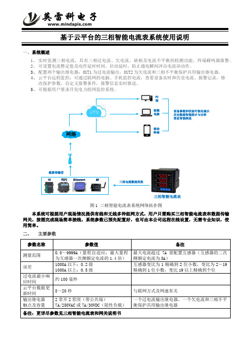
一、系统概述1、 实时监测三相电流,具有三相过电流、欠电流、缺相及电流不平衡的检测功能,终端蜂鸣器报警。
2、 可设置电流整定值及动作延时时间、启动延时,防止通电瞬间冲击电流误动作。
3、 配置两个输出继电器:OUT1为过电流输出,OUT2为欠电流和三相不平衡保护共用输出继电器。
4、 云平台远程监控:可通过联网的电脑、手机监控电流,查看设备实时和历史电流、报警记录,修改保护参数,自定义报警条件,报警信息实时推送。
5、可根据用户要求开发电力组网监控系统。
4GWIFIEthernetRF数据传输层PC 端便携电脑移动终端三相智能电流表设备参数和状态可视化展示历史数据智能统计与分析消息智能推送图1 三相智能电流表系统网络拓扑图本系统可根据用户现场情况提供有线和无线多种组网方式,用户只需购买三相智能电流表和数据传输网关,按图完成现场简单接线,系统参数已预先配置好,也可由本公司远程在线设置,无需专业知识,使用简单。
二、 主要参数三、组网方式选择及接线本地客户端图2 4G组网接线输图5 有线组网接线图用户根据上面组网方式连接设备,包括RS485端口的A、B端的连接,工作电源的接线。
网关的以太网接口接入本地的路由器或交换机,本公司的网关出厂设置为自动获取动态IP(也可设置为固定IP)。
三相智能电流表和网关的具体接线参见三相智能电流表和网关说明书。
四、手机监控1、扫描微信二维码并关注公众号:进入“英雷科电子”公众号号后,再点击“用户中心”的“用户绑定”,在用户绑定界面输入我公司提供的用户名和密码,完成微信绑定。
2、手机APP的使用。
用户绑定微信后,进入手机APP的首页,见图6,点击监控中心,可以看到当前设备的各状态参数、曲线及历史数据等。
点击首页的“应用”,进入我公司免费为用户开发的一个标准的综合组态应用界面。
用户也可以在首页点击“触发器”,添加微信报警触发条件,如设备参数达到触发条件,将通过微信实时推送报警信息。
正泰三相智能电能表 DTSU666-20 快速安装指南说明书

Three-Phase Smart Energy MeterQuick Installation GuideDTSU666-20DTSU666-20-QIEN-Ver11-202208This manual is applicable to Sungrow Three-phase Smart Energy Meter.Keep the manual in a convenient place for future reference. The latest manual can be acquired at .DTSU666-20ApplicabilityOnly qualified personnel with the following skills are allowed to perform the work described in this document:Training in the installation and commissioning of the electrical systems.Familiar with the country/regional standards and specifications.Capable of coping with the dangerous and emergency situations during the installation and commissioning.Knowledge of and compliance with this manual and other related documents.Target GroupThe Smart Energy Meter is designed for indoor use only. It is a measuring device detecting the electrical values at the grid-connected point. It cannot be used for billing purposes. The data collected by the Smart Energy Meter on the PV power generation may differ from the data of the main Smart Energy Meter.Any use other than those described in this document does not qualify as appropriate usage and is prohibited. Do not make any modifications to the product.Damage or destruction may be caused to the Smart Energy Meter due to inappropriate usage. The Smart Energy Meter must not be operated beyond the values specified in the technical data.The following figure shows an application example of the Smart Energy Meter in the PV system. The inverterIntended Use* The RS485 cable is included in the accessories of the meter or the inverter.Related components in the scope of delivery: Smart Energy MeterRS485 cable *Quick installation guideDelivery ContentsTechnical Data320Vac ... 460Vac***/0.333V Nominal voltage Input voltage range 50Hz/60HzGrid frequency -25 ℃ ... +70 ℃Operating temperature < 75%(non-condensing )Relative humidity 118 x 72 x 65.5 mmDimensions (W x H x D)RS485 cableDTSU666-20Quick guideCurrent TransformerThree-phase Smart Energy Meter and its terminalsThree-phase Smart Energy Meter dimensions100 A CT dimensions250 A CT dimensionsDEFGLeft elevation* The current transformer (CT) is shipped separately or with the inverter.Step 3 Connect the plugs A and B to terminals A and B on the Smart Energy Meter.Mount the Smart Energy Meter to a 35 mm DIN rail. Hook it into the top edge of the rail and press down until it snaps into place.InstallationCable ConnectionThe line conductor L1 supplies power to the Smart Energy Meter. The line conductor L1 and neutral conductor must be connected to the terminal 2 and terminal 10 of the Smart Energy Meter respectively.If there is only L1(to terminal 2), or L2 (to terminal 5), or L3 (to terminal 8), and the neutral conductor (to terminal 10), then the three-phase Smart Energy Meter can be used as a single-phase Smart Energy Meter.Step 1 Turn off solar switch, load switch, main switch and other power switches, and secure them against reconnection.Step 2 Take out the RS485 cable from inverter’s packaging or Smart Energy Meter’s packaging .Output terminals to the load sideA 2, 5, 8, 10D C A, BB LCD display Key Displays active energy and reactive energy, etc SET: confirm the selection or settingsESC: return to a previous menu or cancel the settings →: increase the setting value Communication terminals E 1, 3, 4, 6, 7, 9CT1 Current Input F 31, 33, 34, 36, 37, 39CT2 Current InputG91Power supply of Rogowski coil (5V)Step 4 Strip the insulation from the power wires by 10 mm. Then connect wires to the terminals on the Smart Energy Meter, as shown below. ( Cross-section: 1mm to 6mm )Retrofit (Three-phase hybrid inverter + Three-phase PV inverter + Three-phase grid)Retrofit (Three-phase hybrid inverter + Single-phase PV inverter + Three-phase grid)Retrofit (Single-phase hybrid inverter + Single-phase PV inverter + Single-phase grid)Step 5 For inverter cable connection, refer to the user manual of the corresponding inverter.Step 6 Cover the Smart Energy Meter with the insulating cover or contact protection of the sub-distribution. Switch on the power supply to the sub-distribution.The CT direction must be consistent with the arrow direction as shown in the preceding figure.The maximum torque of 2, 5, 8 and 10 terminal screws is 1.7N.m, and the recommended torque is (1.0 ± 0.1) N.m; The maximum torque of 13, 14, 16, 17, 19, 21, 24 and 25 terminal screws is 0.4N.m, and the recommended torque is (0.20 ± 0.05) N.m.NOTICEFor details about the installation direction and cable connection of the current transformer, please refer to the information on the side of the current transformer.Note:Connect CT1 to terminal 1 and terminal 3 of the smart energy meter, and CT2 to terminal 31 and terminal 33.From the displayed interface, the electrical parameter and energy data are all primary side data (that is, the multiplied by current and voltage ratios). The energy measuring value will be displayed seven bits, with the displaying range from 0.00kWh to 9999999MWh.Displayed function8First channelPhase A voltage =5.002ACombined phase active power 23When RS485 communicating, the telephone sign will flashes.The communication address of Modbus protocol is 1 decimal data (1 ~ 254), and the factory default baud rate is 9600bps, N.8.1; E1 means even check one stop bit, O1 means odd check one stop bit, N2 means two stop bits without check, N1 means one stop bits without check.PFb=0.500PFc=-0.500The meter parameters have been set before delivery. It can be installed directly after acception and there is no need to set parameters again. Button description: “SET” represents “confirm” or “cursor shift” (when input digits), “ESC” represents “exit”, and “→” represents “add”. The password is 701 by default.Programming functionProgramming ParameterProgramming ParameterParameterValue range DescriptionVoltage ratio, used for setting the voltage ratio of the input loop.When the voltage is connected to the line via the transformer, Pt= the rated voltage of the primary loop / the rated voltage of the secondary circuit.When the voltage is directly connected to the line, Pt shall be set as 1.0.1: 6452: n.23: n.14: E.15: O.1Settings for communication stop bit and Parity: bits1: 645mode2: None parity, 2 stop bits, n.23: None parity, 1 stop bit, n.14: Even parity, 1 stop bit, E.15: Odd parity, 1 stop bit, O.10: 1.2001: 2.400 2: 4.8003: 9.600Communication baud rate: 0: 1.200 bps 1: 2.400 bps 2: 4.800 bps 3: 9.600 bps1 ~ 254 Communication address 0: n.34 1: n.33Option for wiring mode:0: n.34 represents three phase four wire 1: n.33 represents three phase three wire0: P01: P1Pulse output:0 ~ 30Display in turns(second) 0: Timely display1 ~ 30: Time interval of actual display 0 ~ 30Backlight lighting time control(minute)0: Normally light 1 ~ 30: Backlight lighting time without button operation1 ~ 880.1 ~ 1.01:CT01:100A/333mV 2:CT02:250A/333mV 3:CT03:400A/333mV 4:CT04:500A/333mV 5:RS01:1000A/333mV 6:RS02:2000A/333mV 7:RS03:3000A/333mV 8:RS04:4000A/333mVP0: First channel actsive energy pulseP1: Second channel actsive energy pulseWhen input digits, “ ” can be used as cursor “ - ”motion button, “ ”is “add” button, “ ”is Exit the programming operation interface or switch to the character interface from digit modification interface, add from the beginning after setting the digit to the maximum value.Troubleshooting1. If the wiring mode is incorrect, please connect based on the correct wiringmode.2. If the supplied voltage is abnormal, pleasesupply the voltage on the instrument specification.1. If any problems for the communication cable, please change the cable.2. Set the address, baud rate, data bit and parity bit of the instrument to be the same as the inverter through buttons and so as the "parameter setting".1. For wrong wiring, please connect based on the correct wiring mode.2. If a negative value is displayed, change the cable connection mode of the current transformer to ensure that the high and low ends are connected properly.No display after theinstrument being powered onAbnormal RS485 communicationPower metering inaccuracy1. Incorrect wiring mode.2. Abnormal voltage supplied for theinstrument.1. The RS485 communication cable is disconnected, short circuit or reversely connected.2. The address, baud rate, data bit and parity bit of the instrument is not in accordance with the inverter.whether the corresponding phase sequence of voltage and current is correct.2. Check whether the high and low ends of the current transformer inlet are reversely connected. Pa, Pb , and Pc are abnormal if the values are negative.21。
- 1、下载文档前请自行甄别文档内容的完整性,平台不提供额外的编辑、内容补充、找答案等附加服务。
- 2、"仅部分预览"的文档,不可在线预览部分如存在完整性等问题,可反馈申请退款(可完整预览的文档不适用该条件!)。
- 3、如文档侵犯您的权益,请联系客服反馈,我们会尽快为您处理(人工客服工作时间:9:00-18:30)。
正泰pd6663s4电流设置说明书
以正泰PD6663S4电流设置说明书为标题,本文将详细介绍如何正确设置正泰PD6663S4电流,以确保设备的正常运行和安全使用。
一、产品概述
正泰PD6663S4是一款高品质的电流设置装置,广泛应用于各种电力系统中。
它具有精确可靠的电流设置功能,能够满足不同电力系统对电流的需求。
本说明书将针对PD6663S4的电流设置进行详细介绍。
二、设备参数
在进行电流设置之前,我们首先需要了解PD6663S4的一些基本参数,以便正确操作。
以下是PD6663S4的主要参数:
1. 额定电流:设备能够输出的最大电流值。
2. 电流精度:设备输出电流的精度。
3. 电流范围:设备能够输出的电流范围。
4. 输出方式:设备电流输出的方式,可以是直流或交流。
5. 保护功能:设备具备的过流保护和短路保护功能。
三、电流设置步骤
根据PD6663S4的参数和功能,我们可以按照以下步骤进行电流设置:
1. 确定设备的额定电流:根据实际需求和设备规格,确定需要设置
的电流数值。
2. 调整输出范围:根据设备的电流范围,调整输出范围以适应设备的需求。
3. 选择输出方式:根据实际使用情况,选择合适的输出方式,可以是直流或交流。
4. 设置电流精度:根据实际需求和设备的精度要求,设置合适的电流精度。
5. 启动保护功能:确保设备的过流保护和短路保护功能已经启动,以保证设备的安全运行。
四、注意事项
在进行电流设置时,还需要注意以下几点:
1. 确保设备与电源连接正确,避免反接或短路等情况。
2. 在设置电流时,应逐步增加电流数值,避免突然调整过大造成设备损坏。
3. 在设置完成后,应检查设备的输出电流是否符合预期,以确保设备正常工作。
4. 在使用过程中,注意设备的温度和运行状态,避免过热和异常运行。
五、故障排除
如果在使用过程中遇到了设备故障或异常情况,可以按照以下步骤进行排除:
1. 检查设备的电源连接是否正常,排除电源故障。
2. 检查设备的输出线路是否有松动或短路现象,排除线路故障。
3. 检查设备的保护功能是否正常,如过流保护和短路保护。
4. 如仍无法解决故障,建议联系正泰售后服务中心进行维修或更换。
六、总结
通过本说明书的介绍,我们了解了正泰PD6663S4电流设置的步骤和注意事项。
正确设置电流对设备的正常运行至关重要,希望本文内容能够帮助您正确使用PD6663S4,并确保设备的安全和稳定运行。
如有更多疑问或需求,请咨询正泰售后服务中心。