片式NTC热敏电阻器-SDNT系列
SUNLORD-1[1]热敏电阻规格书
![SUNLORD-1[1]热敏电阻规格书](https://img.taocdn.com/s3/m/0bb12b29cfc789eb172dc8b0.png)
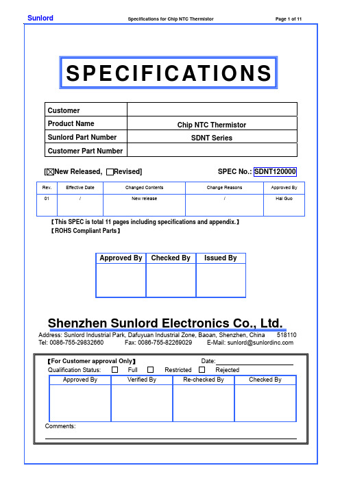
SPECIFICATIONS
B constant (25-50℃)
B 常数 K
B25/50 3250±3% 3250±3% 3250±3% 3250±3% 3450±3% 3450±3% 3450±3% 3450±3% 3450±3% 3950±3% 3950±3% 3950±3% 3450±3% 3950±3% 3380±3% 3450±3% 3450±3% 3500±3% 4100±3% 4100±3% 4150±3% 4150±3% 4150±3% 4250±3% 4300±3% 4350±3% 4400±3%
SPECIFICATIONS
B constant (25-50℃)
B 常数 K
B25/50 3500±3% 3500±3% 3950±3% 3450±3% 3950±3% 3500±3% 4050±3% 4050±3% 4150±3% 4150±3% 4150±3% 4250±3% 4300±3% 4350±3% 4400±3% 4500±3% 4500±3%
■1
规格特性
SDNT1005 TYPE
Part Number 型号
Units 单位 Symbol 符号 SDNT1005X220□3250H SDNT1005X400□3250H SDNT1005X101□3250H SDNT1005X151□3250H SDNT1005X221□3450H SDNT1005X331□3450H SDNT1005X471□3450H SDNT1005X681□3450H SDNT1005X102□3450H SDNT1005X152□3950H SDNT1005X222□3950H SDNT1005X332□3950H SDNT1005X472□3450H SDNT1005X682□3950H SDNT1005X103□3380H SDNT1005X153□3450H SDNT1005X223□3450H SDNT1005X333□3500H SDNT1005X473□4100H SDNT1005X503□4100H SDNT1005X683□4150H SDNT1005X104□4150H SDNT1005X154□4150H SDNT1005X224□4250H SDNT1005X334□4300H SDNT1005X474□4350H SDNT1005X684□4400H
各大电阻生产厂家电阻资料总结

同上
50ppm/℃
MG
N
12 H
贴片排阻 贴片电阻排 贴片排阻
贴片排阻 压敏电阻
N是额定功率代号,其中
J=1W,
型号代码:其中06代
MG代表合金片式 K=1.5W,L=2W,M=2.5W,N= 表1206,10代表
固定电阻器
3W
1210,12代表2512 温度系数,同上
RCM
L
08
W
W代表端子形
型号代号:T代表0402 端子数,分为04和08 状,W代表凸电
型,G表示通用型 3.3V
F
NR
05
K
电阻直径:05=5mm,
07=7mm,10=10mm,
风华高科
非线性电阻
14=14mm,20=20mm 误差
WTR
08D
100 M
晶片直径:
05D=5mm,10D=10mm,14D= 前两位表示压敏电阻
14mm,20D=20mm,25D=25m 数值,第三位表示零
RCM代表厚膜片式 型,L代表0603型,C代 分别对应四个端子和 极直角,V代表
网络电阻器
表1206型
八个端子
凸电极缺角
EXB
3
8V
尺寸大小:1=0201*2;
2=0402*2、0402*4、 引脚端子:4代表4个
0402*8;3=0603*2、 引脚,8代表8个引
产品代码
0603*4;S=0805*4
X7R
A=200V,B=500V,C=100
BME非标准尺
Z5U
0V,D=2000V,E=3000V,
寸,B表示BME标
Y5V
Y=250V,Z=63V
SDNT2012X103J3450HTF
1. ScopeThis specification applies to SDNT series of chip NTC thermistors. 2.Product Description and Identification (Part Number) 1) DescriptionExample:SDNT series of multi-layer chip NTC thermistors. 2)Product Identification (Part Number)SDNT ※※※※ X ○○○ ※ □□□□ ◎ T F ① ② ③ ④ ⑤ ⑥ ⑦ ⑧ ⑨3. Electrical CharacteristicsPlease refer to Appendix A (Page 8~11).1) Operating and storage temperature range (individual chip without packing): -55℃ ~ +125℃ 2) Storage temperature range (packing conditions): -10~+40 and RH 75% (Max.)℃℃4. Shape and Dimensions1) Dimensions: See Fig.4-1 and Table 4-1. 2) Recommended PCB pattern for reflow soldering: See Fig.4-2 and Table 4-1.① Type SDNT Chip NTC Thermistor ② External Dimensions (L×W) [mm] 0603 [0201] 0.6×0.3 1005 [0402] 1.0×0.5 1608 [0603] 1.6×0.8 2012 [0805]2.0×1.25③ Internal CodeX④ Nominal Zero-Power Resistance (K Ω)Example Nominal Value 103 10 223 22 104 100⑤ Resistance Tolerance F ±1% H ±3% J ±5%K ±10% ⑦ B Constant Tolerance F ±1% H ±3% ⑥ Nominal B Constant (25 to 50)℃℃Example Nominal 3450 3450K 4250 4250K ⑧ PackagingTTape & Reel⑨ HSF ProductsHazardous Substance Free ProductsType L W T a ABC0603 [0201] 0.6±0.05 [0.024±0.002] 0.3±0.05 [0.012±0.002] 0.3±0.05 [0.012±0.002] 0.15±0.05 [0.006±0.002] 0.20~0.30 0.20~0.30 0.30~0.35 1005 [0402] 1.0±0.15 [0.039±0.006] 0.5±0.15 [0.020±0.006] 0.5±0.15 [0.020±0.006] 0.25±0.1 [0.010±0.004] 0.45~0.55 0.40~0.50 0.45~0.55 1608 [0603] 1.6±0.15 [0.063±0.006] 0.8±0.15 [0.031±0.006] 0.8±0.15 [0.031±0.006] 0.3±0.2 [0.012±0.008] 0.60~0.80 0.60~0.80 0.60~0.80 2012 [0805]2.0 ±0.2 [0.079 ±0.008]1.25±0.2 [0.049±0.008]0.85±0.2 [0.033±0.008]0.5±0.3 [0.020±0.012]0.80~ 1.200.80~ 1.200.90~ 1.60[Table 4-1] Unit: mm [inch]Fig. 4-2Fig. 4-15. Test and Measurement Procedures5.1 Test Conditions5.1.1 Unless otherwise specified, the standard atmospheric conditions for measurement/test as:20±15℃a. AmbientTemperature:b. Relative Humidity : 65±20%c. Air Pressure: 86kPa to 106kPa5.1.2 If any doubt on the results, measurements/tests should be made within the following limits:20±2℃Temperature:a. Ambientb. Relative Humidity: 65±5%c. Air Pressure: 86kPa to 106kPa5.2 Visual Examinationa. Inspection Equipment: 20× magnifier5.4 Reliability Test*1: For F and H tolerance code, the change of R25 should be within ±1% and ±3% respectively. For others, the change of R25 should be within ±5%.*2: For F code tolerance, the change of B constant should be within ±1%. For others, the change of B constant should be within ±2%.6. Packaging, Storage and Transportation6.1 Packaging6.1.1 Tape Carrier Packaging:Packaging code: Ta. Tape carrier packaging are specified in attached figure Fig.6.1-1~4b. Tape carrier packaging quantity please see the following table:Type 0603[0201] 1005[0402] 1608[0603] 2012[0805]T(mm) 0.3±0.05 0.5±0.15 0.8±0.15 0.85±0.2Tape Paper Tape Paper Tape Paper Tape Paper TapeQuantity 15K 10K 4K 4K(1). Taping Drawings (Unit: mm)Remark: The sprocket holes are to the right as the tape is pulled toward the user.(2) Taping Dimensions (Unit: mm)(3) Reel Dimensions (Unit: mm)6.2 Storagea.Package must be stored at 40 or less and 70% RH or less.℃ b. The solderability of the external electrode may be deteriorated if packages are stored where they are exposed to dust ofharmful gas (e.g. HCl, sulfurous gas of H 2S)c. Packaging material may be deform-ed if package are stored where they are exposed to heat of direct sunlight.d.Solderability specified in Clause 5.4.6 shall be guaranteed for 3 months from the date of delivery on condition that they are stored at the environment specified in Clause 3 .For those parts, which passed more than 3 months shall be checked solder-ability before use.7. RecommendedSoldering Technologies7.1 Re-flowing Profile:△ Preheat condition: 150 ~200/60~120℃sec. △ Allowed time above 217℃: 60~90sec. △ Max temp: 260℃△ Max time at max temp: 10sec. △ Solder paste: Sn/3.0Ag/0.5Cu △ Allowed Reflow time: 2x maxType A B P Tmax 0603[0201]0.40±0.10.70±0.1 2.0±0.05 0.55 1005[0402]0.65±0.11.15±0.12.0±0.05 0.8Fig. 6.1-410.0±1.5mm4.3±0.2mm4.0±0.1mm5.0±0.1mmType A B P Tmax 1608[0603] 1.0±0.2 1.8±0.2 4.0±0.1 1.1 2012[0805]1.5±0.22.3±0.2 4.0±0.1 1.1Chip CavityDirection of FeedChip CavityDirection of FeedFig 6.1-2[Note: The reflow profile in the above table is only for qualification and is not meant to specify board assembly profiles. Actual board assembly profiles must be based on the customer's specific board design, solder paste and process, and should not exceed the parameters as theReflow profile shows.]26015020021725℃7.2 Iron Soldering Profile.△ Iron soldering power: Max.30W △ Pre-heating: 150 / 60 sec. ℃ △ Soldering Tip temperature: 350Max.℃ △ Soldering time: 3 sec Max. △ Solder paste: Sn/3.0Ag/0.5Cu △ Max.1 times for iron soldering[Note: Take care not to apply the tip of the soldering iron to the terminal electrodes.]8. Supplier Informationa) Supplier:Shenzhen Sunlord Electronics Co., Ltd. b) Manufacturer:Shenzhen Sunlord Electronics Co., Ltd. c) Manufacturing Address:Sunlord Industrial Park, Dafuyuan Industrial Zone, Guanlan, Shenzhen, China Zip: 518110Tc ℃350℃Appendix A: Electrical Characteristics I.SDNT0603 SeriesII. SDNT1005 SeriesPart NumberResistance at 25℃R25 (k Ω)B constant (25-50) (K)℃Max. PermissiveOperating Current (25℃)(mA)Thermal Time ConstantDissipation Factor (mW/)℃ Rated Electric Power (mW)SDNT0603X103□3380◎TF 10 3380 0.31 SDNT0603X683□4150◎TF 68 4150 0.11 SDNT0603X104□4150◎TF 100 4150 0.10<3sec 1.0 100Part NumberResistance at 25℃R25 (k Ω)B constant (25-50) (K)℃Max. PermissiveOperating Current (25℃)(mA)Thermal Time ConstantDissipation Factor (mW/)℃ Rated ElectricPower (mW)SDNT1005X220□3380◎TF 0.022 3380 6.7 SDNT1005X400□3380◎TF 0.040 3380 5.0 SDNT1005X101□3380◎TF 0.10 3380 3.1 SDNT1005X151□3380◎TF 0.15 3380 2.5 SDNT1005X221□3450◎TF 0.22 3450 2.1 SDNT1005X331□3450◎TF 0.33 3450 1.7 SDNT1005X471□3450◎TF 0.47 3450 1.4 SDNT1005X681□3450◎TF 0.68 3450 1.2 SDNT1005X102□3450◎TF 1.0 3450 1.0 SDNT1005X152□3950◎TF 1.5 3950 0.81 SDNT1005X222□3950◎TF 2.2 3950 0.67 SDNT1005X332□3950◎TF 3.3 3950 0.55 SDNT1005X472□3950◎TF 4.7 3950 0.46 SDNT1005X682□3950◎TF 6.8 3950 0.38 SDNT1005X103□3380◎TF 10 3380 0.31 SDNT1005X103□3950◎TF 10 3950 0.33 SDNT1005X103□4050◎TF 10 4050 0.33 SDNT1005X153□3450◎TF 15 3450 0.25 SDNT1005X223□3950◎TF 22 3950 0.23 SDNT1005X333□3500◎TF 33 3500 0.14 SDNT1005X473□4100◎TF 47 4100 0.12 SDNT1005X503□4100◎TF 50 4100 0.12 SDNT1005X683□4150◎TF 68 4150 0.11 SDNT1005X104□4150◎TF 100 4150 0.10 SDNT1005X104□4250◎TF 100 4250 0.10 SDNT1005X154□4150◎TF 150 4150 0.08 SDNT1005X224□4250◎TF 220 4250 0.06 SDNT1005X334□4300◎TF 330 4300 0.05 SDNT1005X474□4350◎TF 470 4350 0.04 SDNT1005X684□4400◎TF 680 4400 0.03 <3sec 1.0 100III. SDNT1608 Series . SDNT2012 SeriesPart Number Resistance at 25℃R25 (kΩ)B constant(25-50℃) (K)Max. PermissiveOperatingCurrent (25℃)(mA)Thermal TimeConstantDissipationFactor(mW/℃)RatedElectricPower(mW)SDNT2012X101□3380◎TF 0.10 3380 4.0 SDNT2012X151□3380◎TF 0.15 3380 3.5 SDNT2012X221□3450◎TF 0.22 3450 3.0SDNT2012X331□3450◎TF 0.33 3450 2.5 SDNT2012X471□3450◎TF 0.47 3450 2.0 SDNT2012X681□3450◎TF 0.68 3450 1.7 SDNT2012X102□3450◎TF 1.0 3450 1.4 <5sec 2.0 200Part Number Resistance at 25℃R25 (kΩ)B constant(25-50) (K)℃Max. PermissiveOperatingCurrent (25℃)(mA)Thermal TimeConstantDissipationFactor(mW/)℃Rated ElectricPower (mW)SDNT1608X101□3380◎TF 0.10 3380 3.1SDNT1608X151□3380◎TF 0.15 3380 2.5SDNT1608X221□3450◎TF 0.22 3450 2.1SDNT1608X331□3450◎TF 0.33 3450 1.7SDNT1608X471□3450◎TFTF 0.47 3450 1.4SDNT1608X681□3450◎TF 0.68 3450 1.2SDNT1608X102□3450◎TF 1.0 3450 1.0SDNT1608X152□3450◎TF 1.5 3450 0.81SDNT1608X222□3950◎TF 2.2 3950 0.67SDNT1608X302□3950◎TF 3.0 3950 0.55SDNT1608X332□3950◎TF 3.3 3950 0.55SDNT1608X472□3500◎TF 4.7 3500 0.44SDNT1608X472□3950◎TF 4.7 3950 0.46SDNT1608X502□3950◎TF 5.0 3950 0.44SDNT1608X682□3950◎TF 6.8 3950 0.38SDNT1608X103□3450◎TF 10 3450 0.31SDNT1608X103□3950◎TF 10 3950 0.33SDNT1608X153□3950◎TF 15 3950 0.25SDNT1608X223□4050◎TF 22 4050 0.21SDNT1608X333□4050◎TF 33 4050 0.17SDNT1608X473□4150◎TF 47 4150 0.14SDNT1608X503□4150◎TF 50 4150 0.13SDNT1608X683□4150◎TF 68 4150 0.12SDNT1608X104□4250◎TF 100 4250 0.10SDNT1608X154□4300◎TF 150 4300 0.08SDNT1608X224□4350◎TF 220 4350 0.06SDNT1608X334□4400◎TF 330 4400 0.05SDNT1608X474□4500◎TF 470 4500 0.04SDNT1608X684□4500◎TF 680 4500 0.03SDNT1608X135□4700◎TF 1300 4700 0.02<5sec 1.0 100Part NumberResistance at 25℃R25 (k Ω)B constant (25-50℃) (K)Max. PermissiveOperating Current (25℃)(mA)Thermal Time ConstantDissipation Factor (mW/℃)Rated Electric Power (mW)SDNT2012X152□3950◎TF 1.5 3950 1.2 SDNT2012X202□3950◎TF 2.0 3950 1.0 SDNT2012X222□3950◎TF 2.2 3950 0.90 SDNT2012X332□3950◎TF 3.3 3950 0.72 SDNT2012X472□3950◎TF 4.7 3950 0.65 SDNT2012X502□3950◎TF 5.0 3950 0.60 SDNT2012X682□3950◎TF 6.8 39500.50 SDNT2012X103□3450◎TF 10 3450 0.40 SDNT2012X103□3950◎TF 10 3950 0.44 SDNT2012X153□3500◎TF 15 3500 0.32 SDNT2012X223□4050◎TF 22 4050 0.31 SDNT2012X333□4050◎TF 33 4050 0.24 SDNT2012X473□4150◎TF 47 4150 0.20 SDNT2012X503□4150◎TF 50 4150 0.18 SDNT2012X683□4150◎TF 68 4150 0.16 SDNT2012X104□4250◎TF 100 4250 0.14 SDNT2012X154□4300◎TF 150 4300 0.11 SDNT2012X224□4350◎TF 220 4350 0.08 SDNT2012X334□4400◎TF 330 4400 0.06 SDNT2012X474□4500◎TF 470 4500 0.05 SDNT2012X684□4500◎TF 680 4500 0.04 SDNT2012X135□4700◎TF 1300 4700 0.03<5sec 2.0 200※□: Please specify the tolerance code of R25 (F=±1%, H=±3%, J=±5%, K=±10%). ※◎: Please specify the tolerance code of B value (F=±1%, H=±3%). TYPICAL ELECTRICAL CHARACTERISTICSSunlord Specifications for Chip NTC Thermistor Page 11 of 11。
热敏电阻参数
No mechanical damage △R25≤±3%
Preheat Temperature:100-150℃. Solder Temperature: 260±10℃.Dipping Time: 10±1s
大于 95%的覆盖面积 95% Cover Min
无可见损伤 No mechanical damage
R:周围温度T(K)时的电阻值 (K:绝对温度) R0:周围温度T0(K)时的电阻值 B:热敏电阻的B常数
2. B常数 如 (1) 公式 :
B=ln(R/R0)/(1/T - 1/T0) …… (2)
3. 热扩散常数(耗散系数δ) 当在周围温度T1下电功率为P(mW)且热敏 电阻温度升高T2,则有如下公式:
没有机械损伤;R25 阻值变化±3%以
内;B 值(B25/85)变化不超过±2%。
温度:125±2℃。时间:1000±12h。 Temperature:125±2℃
No mechanical damage;R25 change Time:1000±12h。
within ± 3% ; B-CONSTANT(B25/85)
test
耐高温测试 High- Thermal test
高温负荷测试试验 Heat resistance (High- Temperature
load)
没有机械损伤;R25 阻值变化±3%以 温度:40±2℃;湿度:90-95%相对湿度;时间:500±12h;
内;B 值(B25/85)变化不超过±2%。 施加电流:工作电流。 No mechanical damage;R25 change Temperature:40±2℃。 Humidity:90-95%RH。 within ± 3% ; B-CONSTANT(B25/85) Time:500±12h。 Applied current:working current。 change within ±2%。
IBM Network Switche Manual说明书
11 叠层片式压敏电阻器 SDV 系列
片式三端 EMI 滤波器 MFL 系列
12 叠层片式热敏电阻器 SDNT 系列
4 叠层片式铁氧体磁珠 HZ&HPZ&GZ 系列 叠层片式压敏电阻器 SDV 系列
投影机
5 叠层片式铁氧体磁珠 GZ/SZ/PZ&UPZ 系列 绕线片式铁氧体电感 SDWL-F 系列 绕线功率电感 SWPA 系列
6 叠层片式铁氧体磁珠 PZ&UPZ 系列
绕线片式共模扼流器 SDCW2012 系列
7
9
绕线片式共模扼流器 SDCW2012 系列
叠层片式压敏电阻器 SDV 系列
叠层片式铁氧体磁珠 PZ&UPZ 系列
应用指南 2009/12/08
8 绕线片式共模扼流器 SDCW2012H 系列 叠层片式压敏电阻器 SDV 系列
10 叠层片式铁氧体磁珠 GZ/SZ/PZ&UPZ 系列 绕线片式铁氧体电感 SDWL-F 系列
前面板控制
红外线传输
11 视频输出接口
LCD/DMD 12
灯泡光源
Sunlord
1 叠层片式铁氧体磁珠 SZ 系列
2 叠层片式铁氧体电感 S
绕线片式铁氧体电感 SDWL-F 系列
叠层片式铁氧体磁珠 GZ&SZ&PZ&UPZ 系列
3 叠层片式铁氧体磁珠 GZ/SZ/PZ&UPZ 系列
Sunlord
投影机
应用指南 2009/12/08
A/V S-Video VGA yPrPb
1 Clock
2 CPU
DSP
9 LAN I/F
A/D 转换器
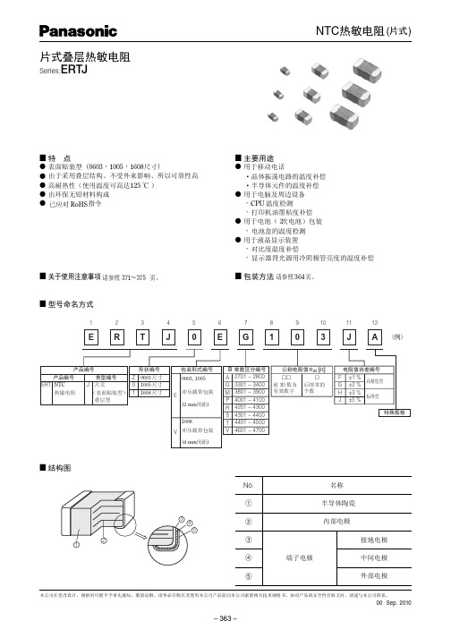
NTC热敏电阻(片式)片式叠层热敏电阻
ɹ单ɹ位 NN
L1, L2 0.15±0.05 0.25±0.15
0.3±0.2
■ 包装方法
● 标准包装数量
形状 产品厚度 编号 (mm)
Z(0603) 0.3 0(1005) 0.5 1(1608) 0.8
带状包装种类 冲压载带包装 冲压载带包装
间距 数量 (mm)(个/卷盘)
2 15,000
2 10,000
4
4,000
● 冲压载带包装( N N ɹ间ɹ距ɹ) 尺寸
t
输送定位孔 产品贴装凹孔
φD0
A
● 带状包装用卷盘
W1 E
C
D
W2 A
B
编号
单位 (mm)
φA 180–03
φB
C
D
E
W1
W2
60.0+10.0 13.0±0.5 21.0±0.8 2.0±0.5 9.0+10.0 11.4±1.0
+0.1 0
0.55 0.36
max. ±0.03
● 冲压载带包装( N N ɹ间距ɹ) 尺寸
t1
输送定位孔 产品贴装凹孔
φD0
● 引线部空区规格 头部
盖带
100 min. 空区 400 min.
载带尾部
B
FE W
A
t2
装有零部件时
P1 P2 P0 拉出方向
t1
输送定位孔
产品贴装凹孔
φD0
A
B FE W
t2
装有零部件时
P1 P2 P0 拉出方向
编号 A B W F E P1 P2 P0 φD0 t1 t2
单位 (mm)
sunlord Game Machine Application Note说明书
3
4
6
绕线片式铁氧体电感 SDWL-F 系列
片式 NTC 热敏电阻器 SDNT 系列
叠层片式铁氧体磁珠 SZ 系列
游戏机
5
叠层片式铁氧体磁珠 PZ&UPZ 系列
绕线片式共模扼流器 SDCW 系列
叠层片式压敏电阻器 SDV 系列
8
叠层片式铁氧体磁珠排 ARZ 系列
绕线片式共模扼流器 SDCW 系列
9
叠层片工铁氧体磁珠 GZ&PZ 系列
Sunlord
3 DVD
4 硬盘驱动器
5 USB 接口
6 读卡器
7 IEEE1394 接口
1 CPU
2 GPU
游戏机
10 视频输出
主控制 处理器
8 控制器接口
11 蓝牙
12 DC-DC 变换器
9 游戏控制器
应用指南 2009/05/15
Sunlord
1
叠层片式铁氧体磁珠 SZ&HZ 系列
2
叠层片式铁氧体磁珠 SZ&HZ 系列
绕线片式共模扼流器 SDCW 系列
7
叠层片式铁氧体磁珠 PZ&UPZ 系列
绕线片式共模扼流器 SDCW 系列
10
叠层片式铁氧体磁珠 SZ&HZ 系列
应用指南 2009/05/15
11
叠层片式天线 SLDA 系列 叠层片式陶瓷电感 SDCL 系列 叠层片式 LC 滤波器 SLFB 系列
12
叠层片式铁氧体磁珠 PZ&UPZ 系列 绕线片式铁氧体电感 SDWL-F 系列 绕线贴片功率电感 SWPA 系列
推介资料-片式NTC
基本原理图
线性化原理图
产品研发与制造工艺
配料
打粉
球磨
烘料
烘料
二次球磨
打粉
预烧
压 烧成 烧银 测试分选
切割 排胶 表面处理 外观
NTCR的常用参数
零功率电阻值RT Zero-power Resistance 指在规定的温度T时,采用引起电阻值变化相对于总的测量误差来说可 以忽略不计的测量功率测得的电阻值。 NTC热敏电阻的电阻-温度(R-T)关系特性,可用下式数学模型近似表示 : R=Ro EXP[B*(1/T-1/To)] 其中 R , Ro : 绝对温度T(K), To(K)下的零功率电阻值 上式为经验公式,只在额定温度To或额定阻值Ro的有限范围内才具有一定的 精度。在较大温度区间,需要对B进行函数修正: Bt= cT2 + dT + e 这里c、d、e为常数。 T=t(℃) + 273.15 额定零功率电阻值 R25 Rated Zero-power Resistance 即标称电阻值,通常是指在基准温度25℃时测得的零功率电阻值。 热时间常数τ Thermal Time Constant 指热敏电阻器的惰性,即在无功功率状态下,当环境温度突变时,电 阻体温度由初始值变化到最终温度之差的63.2%所需的时间。与测试所用介 质有关。
客户与生产规模
主要客户:
中兴、美的、雅乐思、冠德、TCL 、UPC 、 蓝微、比亚迪 生产规模 :
月生产能力80KK,
谢谢!
NTCR的主要应用 应用范围
1、在各式可充电电池、智能手机中广泛使用, 2、CPU、复印机、传真机、数码产品中广泛使用。 3、高端电子信息、汽车、节能环保、生物电子中也要使用。
NTC贴片100k-3950
-19 991.1 29 83.91 77 13.98
-18 932.5 30 80.37 78 13.54
-17 877.8 31 77.00 79 13.11
-16 826.7 32 73.79 80 12.70
-15 779.0 33 70.74 81 12.31
-14 734.3 34 67.83 82 11.93
包装 1 数量:5 卷
包装 2 数量:12 盒
2. 卷标及标识 2.1 纸带胶盘上有卷标,包括以下内容:
①型号规格
②标称电阻及 B 值
③数量
⑤批号
⑥日期
⑦QC 盖章
2.2 包装盒子或箱子标识以下内容
①型号规格
②标称电阻及 B 值
③数量
⑤批号
⑥日期
⑦QC 盖章
④误差范围 ④误差范围
7.0 贮存方式
①贮存条件:温度:-10~40℃
由于产品外部采用了致密的玻璃保护层与无玻璃保护产品相比在耐酸碱腐蚀性耐潮湿及阻值的稳定性等方面都有显著提高能在恶劣的环境下使用
东莞市星响电子科技有限公司
编号:SK140715A 送样人:沈泽萍
承认书
品名: NTC 热敏电阻 (SMD0805) 供应厂商: 星响电子 发出日期: 2014-7-15
序号 1
代码 尺寸(英制)
D 0402
A 0603
B 0805
C 1206
③ 标称电阻值 为 25℃时的零功率电阻,单位为Ω, 前二位为有效数字,第三位数字表示有效数字后“0”的个数。.
④阻值公差代码(%)
代码
E
阻值公差
±0.5
⑤B 值常数,单位为 K
F ±1.0
片式ntc热敏电阻
片式ntc热敏电阻
片式NTC热敏电阻是一种常用的温度传感器,它由一块热敏电阻片和两个电极组成。
这种电阻片的电阻值随着温度的变化而变化,因此它可以用来测量温度。
片式NTC热敏电阻的优点是尺寸小、响应速度快、精度高、可靠性好、价格低廉等。
它常被应用于家电、汽车、电子设备等领域中的温度测量和控制。
在使用片式NTC热敏电阻时,需要注意其温度范围和阻值范围。
不同型号的片式NTC热敏电阻适用于不同的温度范围和阻值范围。
因此,在使用前需要了解其具体参数,并根据实际需求进行选择。
总之,片式NTC热敏电阻是一种非常实用的温度传感器,具有尺寸小、响应速度快、精度高等优点,可以广泛应用于各种领域的温度测量和控制。
- 1 -。
- 1、下载文档前请自行甄别文档内容的完整性,平台不提供额外的编辑、内容补充、找答案等附加服务。
- 2、"仅部分预览"的文档,不可在线预览部分如存在完整性等问题,可反馈申请退款(可完整预览的文档不适用该条件!)。
- 3、如文档侵犯您的权益,请联系客服反馈,我们会尽快为您处理(人工客服工作时间:9:00-18:30)。
④⑤Βιβλιοθήκη 3380⑥②
外形尺寸(L×W) (mm)
External Dimensions (L×W) (mm)
1005 [0402]
1.0×0.5
1608 [0603] 2012 [0805]
1.6×0.8 2.0×1.25
⑤
电阻值公差
Tolerance of Resistance
F
±1%
H
±3%
J
±5%
Rated Electric
Power 额定功率
sec
mW/℃
mW
t
C
P
<5sec
2.0
200
※□: Please specify the resistance tolerance code (F=±1%, H=±3%, J=±5%, K=±10%). ◎: Please specify the B value tolerance code (F=±1%, H=±3%). And products with other electrical characteristics can be provided upon customer’s request. Please contact your local sales.
Resistance at 25℃ 电阻 kΩ R25 4.7 5.0 6.8 10 10 15 22 33 47 50 68 100 150 220 330 470 680
Resistance at 25℃ 电阻 kΩ R25 0.10 0.15 0.22 0.33 0.47 0.68 1.0 1.5 2.0 2.2 3.3 4.7 5.0 6.8 10 10 15 22 33 47 50
Thermal Time Constant
热时间常数
sec t
Dissipation Factor
耗散因子 mW/℃
C
Rated Electric Power
额定功率
mW P
<3sec
1.0
100
B constant (25-50℃)
B 常数 K
B25/50 3250 3250 3450 3450 3450 3450 3450 3450 3950 3950 3950 3950
K
±10%
⑧
包装 Packing
B
散装 Bulk Package
T
编带 Tape & Reel
F
T
F
⑦
⑧
⑨
③
内部代号 Internal Code
X
⑥
B 常数 B Constant (25-50℃)
Example Nominal Value
3380
3380K
4250
4250K
⑨
无有害物质产品 Hazardous Substance
Thermal Time Dissipation Factor Rated Electric
Constant 热时间常数
耗散因子
Power 额定功率
sec
mW/℃
mW
t
C
P
<5sec
1.0
100
2■
规格特性
SDNT1608 TYPE
Part Number 型号
Units 单位 Symbol 符号 SDNT1608X472□3500◎ SDNT1608X502□3500◎ SDNT1608X682□3950◎ SDNT1608X103□3450◎ SDNT1608X103□3950◎ SDNT1608X153□3500◎ SDNT1608X223□4050◎ SDNT1608X333□4050◎ SDNT1608X473□4150◎ SDNT1608X503□4150◎ SDNT1608X683□4150◎ SDNT1608X104□4250◎ SDNT1608X154□4300◎ SDNT1608X224□4350◎ SDNT1608X334□4400◎ SDNT1608X474□4500◎ SDNT1608X684□4500◎
SDNT2012 TYPE
Part Number 型号
Units 单位 Symbol 符号 SDNT2012X101□3250◎ SDNT2012X151□3250◎ SDNT2012X221□3450◎ SDNT2012X331□3450◎ SDNT2012X471□3450◎ SDNT2012X681□3450◎ SDNT2012X102□3450◎ SDNT2012X152□3950◎ SDNT2012X202□3500◎ SDNT2012X222□3950◎ SDNT2012X332□3950◎ SDNT2012X472□3500◎ SDNT2012X502□3500◎ SDNT2012X682□3950◎ SDNT2012X103□3450◎ SDNT2012X103□3950◎ SDNT2012X153□3500◎ SDNT2012X223□4050◎ SDNT2012X333□4050◎ SDNT2012X473□4150◎ SDNT2012X503□4150◎
用途
● 移动电话,汽车电话,无绳电话等通讯设备
● 打印机,传真机,文字处理机等办公设备 ● 录像机,DVD, CD 等消费类电子设备
APPLICATIONS
● Telecommunication equipments such as cellular phone, automobile phone, cordless phone, etc
SDNT1608 TYPE
Part Number 型号
Units 单位 Symbol 符号 SDNT1608X101□3250◎ SDNT1608X151□3250◎ SDNT1608X221□3450◎ SDNT1608X331□3450◎ SDNT1608X471□3450◎ SDNT1608X681□3450◎ SDNT1608X102□3450◎ SDNT1608X152□3450◎ SDNT1608X152□3950◎ SDNT1608X222□3950◎ SDNT1608X302□3950◎ SDNT1608X332□3950◎
W 0.5±0.15 [.020±.006] 0.8±0.15 [.031±.006] 1.25±0.2 [.049±.008]
T 0.5±0.15 [.020±.006] 0.8±0.15 [.031±.006] 0.85±0.2 [.033±.008]
Unit: mm [inch]
a 0.25±0.1 [.010±.004] 0.3±0.2 [.012±.008] 0.5±0.3 [.020±.012]
Resistance at 25℃ 电阻 kΩ R25 0.022 0.040 0.10 0.15 0.22 0.33 0.47 0.68 1.0 1.5 2.2 3.3 4.7 6.8 10 15 22 33 47 50 68 100 150 220 330 470 680
Resistance at 25℃ 电阻 kΩ R25 0.10 0.15 0.22 0.33 0.47 0.68 1.0 1.5 1.5 2.2 3.0 3.3
X
①
②
③
①
分类 Type
SDNT
片式 NTC 热敏电阻器 Chip NTC Thermistor
④
电阻值 Zero-power Resistance
Example
Nominal Value
101
0.1kΩ
103
10kΩ
⑦
B 值公差
Tolerance of B Constant
F
±1%
H
±3%
103 F
Constant 热时间常数
Dissipation Factor 耗散因子
Power 额定功率
sec
mW/℃
mW
t
C
P
<5sec
1.0
100
B constant (25-50℃)
B 常数 K
B25/50 3250 3250 3450 3450 3450 3450 3450 3950 3500 3950 3950 3500 3500 3950 3450 3950 3500 4050 4050 4150 4150
Free Products F
外观尺寸
SHAPE AND DIMENSIONS
Type SDNT1005
[0402] SDNT1608
[0603] SDNT2012
[0805]
L 1.0±0.15 [.039±.006] 1.6±0.15 [.063±.006] 2.0 ±0.2 [.079±.008]
片式 NTC 热敏电阻器—SDNT 系列
Chip NTC Thermistor – SDNT Series
Operating Temp. : -55℃~ +125℃
特征
● SMD 结构适合高密度安装 ● B 值种类多可满足各种应用 ● 良好的焊接性能
FEATURES
● SMD type suitable for high density mounting ● Series of B constant for various applications ● Excellent solderability
Resistance at 25℃ 电阻 kΩ R25 68 100 150 220 330 470 680
B constant (25-50℃)
B 常数 K
B25/50 4150 4250 4300 4350 4400 4500 4500
Thermal Time