Albin泵
苏州尔泵有限公司产品说明:GSG 漏斗式浇筑式油泥泵 API 610 类别 BB5说明书
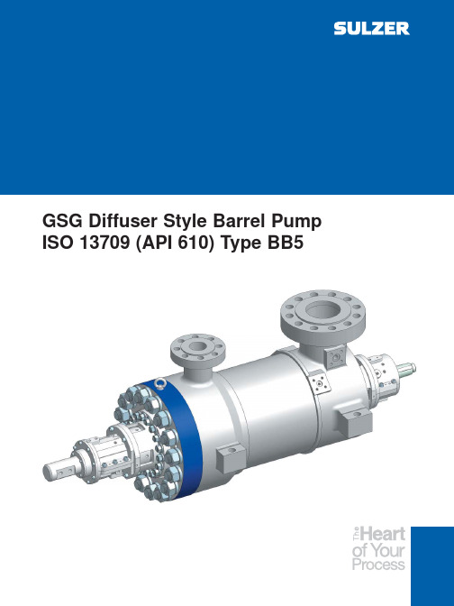
GSG Diffuser Style Barrel Pump ISO 13709 (API 610) Type BB5Extensive Product RangeSulzer Pumps has a long history of providing innovative pumping solutions to business partners in the following industries:Oil & GasHydrocarbon Processing Pulp and Paper Power Generation Food, Metals & Fertilizers Water and WastewaterHydrocarbon ProcessingHydrocarbon extraction plants,refineries, petrochemical plants and gas plants operate sophisticated production processes requiring reliable pumping solutions.Continuous product innovations such as our improved line of hermetically sealed, horizontal and vertical process pumps, are helping the industry improve its operational efficiency.Sulzer Pumps, with its high-quality product line, is known for being able to consistently meet these expectations.All our pumps are engineered in line with the latest standards issued by API, ISO and ANSI in order to ensure reliable and safe operation at your site. The Hydrocarbon Processing Industry is one of the core business segments within Sulzer Pumps.Following industry practice, we further subdivide the segment into:Synfuels Refining Gas Processing Petrochemicals Nitrogenous FertilizerThe market - and therefore our customers - requires specialty applications for each subsegment.Application RangeThousands of GSG pumps are installed around the world. They are found in:Power Plants RefineriesPetrochemical Plants Gas Processing Plants Onshore and offshore water injection servicesOnshore and offshore crude shipping serviceOnshore crude oil, refined product and LPG pipeline servicesHigh pressure and high or low temperatures are GSG services.DesignThe GSG is built to the latest edition of ISO 13709 (API 610). It is a type BB5,horizontal, radially split, diffuser type,multistage barrel pump. The rotor stack can be either inline (all the impellers facing towards the driver) or back-to-back. On the smaller pumps,the inboard seal chamber and bearing housing must be removed for cartridge removal. On larger pumps,the entire cartridge can be removed as an assembly to speed overhaul or re-rate turnaround time.The barrel is available as either a casting or forging with a variety of flange ratings to meet individual specifications. It is normally centerline supported for thermal stability and maximum nozzle load capacity. The barrel closure is either the traditional flanged head-studs and nuts, flanged head-Supernuts™, or Sulzer’s patented Twistlock closure for speedy removal and assembly.The inner cartridge consists of stacked diffuser/impeller sets. A double suction first stage impeller is available on all but the smallest sizes.Axial thrust is compensated by a balance drum for inline stacked rotors.The diffusers hydraulically balance radial forces. For those services where intermediate pressure takeoff is needed, higher flow diffuser/impeller sets can be utilized up to the takeoff stage, and then lower flow sets are used after the takeoff stage to optimize efficiency and performance.When design conditions change, re-rates are similarly achieved using different diffuser/impeller combin-ations, or blank stages—all in the same barrel.For applications on light gravity fluids with many stages, a back-to-back rotor stack is utilized to allow direct drive at normal motor speeds and provide improved rotordynamics. In such rotors, the opposed impellers cancel most of the axial thrust. The center bushing and throttle bushings take most of the residual axial thrust,so the thrust bearing loads are minimal. The back-to-back design allows the use of a 7300 series ball thrust bearing—and saves the substantial cost and maintenance components associated with lube oil systems. For high pressure and high energy levels, inline, or back-to-back stack, high speed, semi-stiff rotor designs are available.Depending upon pump size, power,and rotor design, the pumps can be supplied with ring oil or oil mist lubricated antifriction bearings, ring oil lubricated sleeve radial—ball thrust bearings, or pressure lubricated sleeve radial—tilting pad thrust bearings.MaterialsAll common ISO 13709 (API 610)material combinations are available.GSG Inline Design Features and BenefitsCasing CoverFlanged head, studs/nuts Flanged head, Supernuts™O-ring or spiral wound gasketMechanical SealsThrust Bearingbrass cages, orforce INPRO™with 360°Wear parts offered are the result of a year of wear testing by Sulzer Variety of materials, hardness, and hard coatings available depending on pump material and application PEEK with reduced clearances available on clean fluids for enhanced efficiencyfitsFor HPI applications shrink fit, axially secured impellers, and stepped shaft at each stageBlank stages can be supplied for future conditionsInterstage TakeoffPartial flow takeoff from intermediate stageAble to stack high capacity and low capacitydiffusers/impellers on same rotor for optimized stagetakeoffCommon on boiler feed pumps Available on recycle process applications Saves cost of additional pumpFirst Stage ImpellerLow Nss design is standardDouble suction available on all butsmallest sizesImproved NPSHr designs availableRadial BearingsInpro™bearing isolatorCarbon steel bearing housing with360°supportRing oil or oil mist lubricated rolleror ball bearing with C-3 clearanceRing oil or force feed lubricatedsleeve bearingsavailableRobust Shaft and RotorDesigned for low stress levelFully machinedDynamically balancedStraight bore, tapered bore, orhydraulic fit under couplingavailable per ISO 13709 (API610)BarrelCenterline mounted for thermal stabilityand maximum nozzle load capabilityCast with nozzles and flangesForged barrel with NDE of nozzle weldsWarm-up flow through discharge drain notrequired below 260°C (500°F). Warm-upflow required for higher temperaturesPin-and-key-slot thermal expansionsystemJacketing, insulation or noise blanketsavailablePump Inner Cartridge AssemblyStage casings sealed by dischargepressureFree to expand towards discharge coverduring warm-upInner tie bolts for assembly/disassemblyCoupling hub, inboard radial bearing and inboard seal chamber removal required on small pumps to remove cartridgeLarger pumps have barrel bore diameters larger than bearing housing which allows cartridge to be removed with those partsassembledCenter and throttle bushing absorb residualthrust and only breakdown half of dischargeAxial thrust stable even with worn clearances BearingsInpro™360°First Stage ImpellerLow Nss design is standardDouble suction available on all but smallest sizes Improved NPSHr designs availableBarrelCenterline mounted on hot servicesGSG InlineFulfills the majority of requirements for BB5 pumps with either cast or forged barrels to meet customerspecifications.Multivane diffusers balance radial loads. Balancingdrum takes the majority of axial thrust load. Heavyduty bearings support the rotor and carry residualthrust loads.Smaller size pumps fitted with ring oil lubricated antifriction bearings. Oil mist lubrication optionalAll but smallest sizes may be fitted with pressure lubricated sleeve radial, double acting tilting pad thrust bearings, lube oil systems, bearing RTD’s, X-Y vibration probes and Keyphasor, etc.Maximum number of interchangeable stage pieces minimizes spares parts inventoryIn direct drive applications, clearly the best selection up to stage limits. If still more head is needed, first consider GSG back-to-back and direct drive. If that does not meet head requirement, then consider GSG inline with higher Speed—using gear box or VFD.For very high head and high energy levels beyond GSG back-to-back direct drive capabilities, GSG with semi-stiff rotor design (like Sulzer’s HPcp, HPT pumps) can be offered. Could justify stand-alone, single unit—no standby. Discussion recommended.GSG: Inline and Back-to-Back Design Features and BenefitsGSG Back-to-BackWith up to 16 stages available, fulfills direct driveapplications that require more head than is availablefrom direct drive inline GSGMultivane diffusers balance radial loads. Opposedimpellers balance majority of axial thrust. Centerbushing and throttle bushing take nearly all the residualaxial thrust. Even when clearances are worn, axialand radial loads remain balanced.Fan cooled, ring oil lubricated, sleeve / ball thrust bearing without lube systems are common up to ISO 13709 (API 610) Table 9 limits, or Sulzer limits depending upon application. Significantly reduces installed cost and provides simple, reliable pumps.When even high speed GSG with semi-stiff inline rotor does not meet head requirements, or cannot meet rotordynamic requirements a GSG with semi-stiff back-to-back rotor can be offered.To speed the repair of a GSG pump,larger sizes are designed using that cartridge concept. The pump coupling hub, inboard bearing housing, seal chamber and hydraulic cartridge slide through the barrel for quick removal.Re-installation is just as fast. For evenfaster turnaround, the Sulzer patented Twistlock design puts an end to hours of torquing the barrel cover nuts. For remote locations or offshore this can be especially time and cost saving.Small GSG pump barrel bore are so small that the coupling hub, sealchamber and bearing housing will not fit through. Those parts have to be removed on those pumps before the cartridge is pulled.Rapid pump dismantlingThe innovative Sulzer Twistlock barrel cover design provides effective sealing and eliminates the usual requirements of torquing many fasteners to very high values—taking hours. The Twistlock also reduces the end cover flange area required thus reducing weight—an added bonus for offshore installations.Sulzer’s patented TwistlockThe assembled cartridge can be removed as one piece on larger pumps.Installation sequence:Cover in placeCover introduced and partially rotatedCover locked and securedOther Sulzer Barrel Pump ModelsWhen preferred or for erosive, sandy services, Sulzer’s CP opposed impeller, dual volute barrel pumps are proven performers. Heads to 6,700 m (22,000 ft)Sulzer’s HPcp (inline or back-to-back) is the global leader in large water injection services from 5 MW to 30 MW.Heads to 6,500 m (21,000 ft)Sulzer’s HPT boiler feed pumps are renowned for their reliability. Sizes to over 40 MW (55,000 hp) cover the majority of power plant needs.Performance RangeOperating DataQ (m 3/h)Q (USgpm)Bearing optionsFan cooled ring oil, or oil mist lubricated antifrictionbearings, orRing oil lubricated sleeve radial bearings withantifriction thrust bearing, orForce feed lubricated sleeve radial bearing and double acting tilting pad thrust bearingA variety of bearing instrumentation is available tomeet specificationsRotor and Impeller optionsFor ISO 13709 (API 610) applications, impellers areindividually axially secured and are shrink fit to theshaft—which is stepped under each impeller for ease of assemblyFor other applications a slip-fit impeller stack isavailableStraight bore, tapered bore, or hydraulic fit couplinghub is available per ISO 13709 (API 610)GSG “inline” or “back-to-back” rotor design.Double Suction first stage impeller for lower NPSHr.High temperatures and options for bottoms / residuesProven coke crusher available for services with coke particlesPump warm-up not required below 260°C (500°F).Warm-up flow required for higher temperaturesPin-and-block thermal expansion system provided on hot servicesJacketing, insulation or noise blankets availableGSG OptionsCheck our worldwide offices at*******************************E 00612 10.2004 Copyright ©Sulzer PumpsThis brochure is a general presentation. It does not provide any warranty or guarantee of any kind. Please, contact us for description of the warranties and guarantees offered with our products. Directions for use and safety will be given separately. All information herein is subject to change without notice.。
亚特兰斯科普中心 PAC F1212 泵系统说明书
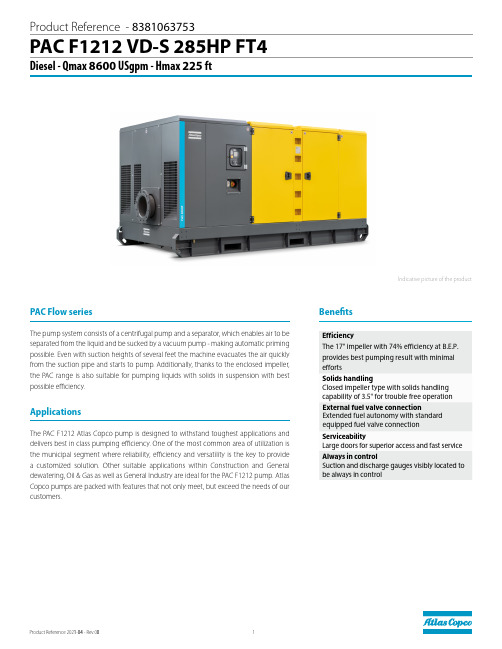
PAC F1212 V D-S 285HP FT4Diesel - Qmax 8600 USgpm - Hmax 225 ftThe pump system consists of a centrifugal pump and a separator, which enables air to be separated from the liquid and be sucked by a vacuum pump - making automatic priming possible. Even with suction heights of several feet the machine evacuates the air quickly from the suction pipe and starts to pump. Additionally, thanks to the enclosed impeller, the PAC range is also suitable for pumping liquids with solids in suspension with best possible efficiency.The PAC F1212 Atlas Copco pump is designed to withstand toughest applications and delivers best in class pumping efficiency. One of the most common area of utilization is the municipal segment where reliability, efficiency and versatility is the key to provide a customized solution. Other suitab le applications within Construction and General dewatering, Oil & Gas as well as General Industry are ideal for the PAC F1212 pump. Atlas Copco pumps are packed with features that not only meet, but exceed the needs of our customers.ApplicationsIndicative picture of the productPAC Flow seriesBenefitsE ff iciencyThe 17" impeller with 74% efficiency at B.E.P. provides best pumping result with minimaleffortsSolids handlingClosed impeller type with solids handling capability of 3.5" for trouble free operation ServiceabilityLarge doors for superior access and fast service Always in controlSuction and discharge gauges visibly located to be always in controlProduct Reference - 8381063753External fuel valve connectionExtended fuel autonomy with standard equipped fuel valve connectionPerformance curvesTest according to UNI EN ISO 9906 standard - level 2Test liquid: clean water, density 62.43 lb/ft3 (8.345 lb/gal)Losses from priming system and check valve not included408012016020024026020002200240018001600140012001000800600400100P [kW]020025015010050Q[m /h]0H [m]8070605040302010[m]056784321[in]Technical dataDimensional drawing。
Edwards XDS35i和XDS35i Enhanced滚动泵系列产品介绍说明书

XDS35i and XDS35i Enhanced FamilyThe XDS35i family of scroll pumps offer proven dry, clean vacuum solutions for a wide range of applications, with smart drive technology to look after the pump and provide world wide performance.Now, a combination of the patented double start scroll form technology and by-pass valves have enabledEdwards to offer the XDS35i Enhanced range of pumps to complement our original family. Take another step.With reduced peak power requirements at roughing pressures and continuous higher roughing speeds these enhanced pumps enable the user to take another step in terms of the performance envelope to address those special applications where roughing performance or the ability to evacuate a large volume is important.XDS35i and XDS35i Enhanced pumps are available as standard pumps with gas ballast, versions of the pump with no Gas Ballast (well suited for rare gas recirculation and gas recovery applications) and the C versions of the pumps featuring Chemraz® internal valves and stainless steel fittings for extra protection from the pumped media. XDS35i DRY SCROLL PUMPSBearing shieldensures separation between process gases and bearing lubrication to ensure clean vacuum and no possibility of contamination to lubrication from process gases, which prolongs bearing life.Smart motor drivemeans consistent performance globally, pump overload protection and remote start/stop capability.High flow gas ballast featureallows pumping of vapours including water vapour at up to 240 gh -1.Simple single sided scroll designallows maintenance to be done in minutes for low cost of ownership and maximum up-time.Take another stepthe Enhanced versions offer up to 20% lower peak powerrequirements during initial pump down which means it has the ability to pump down large volume chambers with no loss of performance and has up to 25% more pumping speed at these roughing pressures which helps on higher frequency cycling applications as well.Features and benefitsPRODUCT DATA SHEETSilencerVibration isolators (packof 4)EMEA UK +44 1444 253 000(local rate) 08459 212223Belgium +32 2 300 0730France +33 1 4121 1256Germany 0800 000 1456Italy + 39 02 48 4471Israel+ 972 8 681 0633ASIA PACIFIC China +86 400 111 9618India +91 20 4075 2222Japan +81 47 458 8836Korea +82 31 716 7070Singapore +65 6546 8408Taiwan +886 3758 1000AMERICAS USA +1 800 848 9800 Brazil+55 11 3952 5000 Publication Number: 3601 0458 01© Edwards Limited 2018. All rights reserved Edwards and the Edwards logo are trademarks of Edwards Limited.Whilst we make every effort to ensure that weaccurately describe our products and services, we give no guarantee as to the accuracy or completeness of any information provided in this datasheet.Edwards Ltd, registered in England and Wales No. 6124750, registered office: Innovation Drive,Burgess Hill, West Sussex, RH15 9TW, UK.GLOBAL CONTACTSA. NW40B. NW25BA333 (13.11)180 (7.09)130 (5.12)50 (1.97)476 (18.74)353 (13.90)212 (8.35)Ø187 (0.28)396 (15.59)223 (8.78)240 (9.45)304 (11.97)DimensionsPerformanceXDS35i0200400600800100012001400160018002000051015202530354045500.0010.010.11101001000P o w e r (W )P u m p i n g s p e e d (m 3/h r )Pressure (mbar)PUMPING SPEED AND POWERXDS35i speedXDS35i E speedXDS35i E powerXDS35i powerThe graph shows typical pump performanceNote that peak power for XDS35i is supplied for a short period of time before the intelligent drive reduces the power and speed XDS35i Enhanced, with its bypass valves, is not limited and will pump down continuously at full speed。
Aquavar ABII 变速泵控制器安装、操作和故障排除手册说明书
U LC USINSTRUCTION MANUALIM156MODELS COVERED:1151AB2 (115V, 4.2A), 1AB2 (230V, 4.2A),2AB2 (230V, 6.9A)2NOTE:• Use Copper wire only.• Suitable for use on a circuit capable of delivering not more than 5000 RMS symmetrical amperes. Branch circuit protection provided by fuses.• Suitable for use in a pollution degree 2 micro-environment.• Motor overload protection provided at 110% of full load current.• In order to maintain the environmental rating integrity of the enclosure, all openings must be closed by equipment rated 3, 3R, 3S, 4, 4X, 6 or 6P .• Maximum ambient temperature is 50º C.Controller Model Number:Controller Serial Number:Pump Model Number:Pump Serial Number:Motor Model Number:Motor SFA:T ank Serial Number:Installer:Installer T elephone Number:Installation Date:Wire Lengths (Feet)Service Entrance to Controller: Controller to Motor:Incoming Voltage:Owner’s InformationSUBJECT PAGE 1. Safety Instructions ...................................................3 2. System Components ................................................3 3. System Design .........................................................4 4. Piping ......................................................................5 5. Mounting the Controller .........................................5 6. Power Supply and Wiring ........................................6 7. Starting the System ...............................................6-7 8. Diagrams ..............................................................8-9 9. T roubleshooting ...............................................10-1110. Controller Dimensions ..........................................1111. Limited W arranty .. (12)T able of ContentsNOTICE: RECORD THE MODEL NUMBERSAND SERIAL NUMBERS FROM THE PUMP AND CONTROLLER IN THIS INSTRUCTION MANUAL FOR FUTURE REFERENCE. GIVE IT TO THE OWNER OR AFFIX IT TO THE CONTROLLER WHEN FINISHED WITH THE INSTALLATION.31: SAFETY INSTRUCTIONS1. This manual is intended to assist in the installation, operation and repair of the system and must be kept with the system.2. Installation and maintenance MUST be performed by properly trained and qualified personnel.3. Review all instructions and warnings prior to perform-ing any work on the system.4. Any safety decals MUST be left on the controller and pump.The system MUST be disconnected fromthe main power supply before attempt-ing any operation or maintenance on the1: SAFETY INSTRUCTIONS electrical or mechanical part of the system. Failure to disconnect electrical power before attempting any op-eration or maintenance can result in electrical shock, burns or death.When in operation, the motor and pumpcould start unexpectedly and cause seri-ous injury.Please review the Aquavar ABII components and insure that you have all the parts and are familiar with their names. Be sure to inspect all components Goulds W ater T echnology supplies for shipping damage.Aquavar ABII:1. Pump with Motor2. Aquavar ABII Controller with Integral Pressure Sensor Cable3. Pressure T ank (supplied on some models)4. Pressure Sensor5. Mounting Kit6. T ank T ee with Pipe Plug7. Pressure Gauge WARNINGDO NOT power the unit or run thepump until all electrical and plumb-ing connections, especially the pressure sensor connection, are completed. Thepump should not be run dry. All electrical work must be performed by a qualified technician. Always follow the NationalElectrical Code (NEC), or the Canadian Electrical Code (CEC) as well as all local, state and provincial codes. Code questions should be directed to your local electrical inspector. Failure to follow electrical codes and OSHA safety standards may result in personal in-jury or equipment damage. Failure to follow manufac-turer's installation instructions may result in electrical shock, fire hazard, personal injury, death, damage to equipment, unsatisfactory performance and may void manufacturer's warranty.2: SYSTEM COMPONENTS4codes.Home SupplyWater MainHome SupplyWell SupplyNOTE: Systems MUST be designed by qualified technicians only and meet all applicable state and local code requirements.The following diagrams show a typical system using the Aquavar ABII Constant Pressure System. Connection can be made directly to a water supply or water can be drawn from a supply tank. Diagram #1 shows a typical set up for a supply tank.Diagram #2 shows a set-up for municipal water connection. This allows pump maintenance without main line shut-off.3: SYSTEM DESIGN5GeneralNOTE: All plumbing work must be performed by a qualified technician. Always follow all local, state and provincial codes.A proper installation requires a pressure relief valve, a ¼" female N.P .T. threaded fitting (found on tank tee) for the pressure sensor, and properly sized pipe. Piping should be no smaller than the pump discharge and/or suction connections. Piping should be kept as short as possible. Avoid the use of unnecessary fittings to minimize friction losses.Some pump and motor combinationssupplied with this system can create over 200 PSI. Select pipe and fittings accordinglycodes for piping requirements in your area.All joints must be airtight. Use T eflon tape or another type of pipe sealant to seal threaded connections. Please be careful when using thread sealant as any excess that gets inside the pipe may plug the pressure sensor.Galvanized fittings or pipe should never be connected directly to the stainless steel discharge head or casing as galvanic corrosion may occur. Barb type connectors should always be double clamped.Pressure T ank, Pressure Relief Valve andDischarge PipingThe standard Hydro-Pro tanks have a pre-charge of 38 PSI. Y ou may set the tank pre-charge anywhere between this value and 10 PSI below the system operating pressure. Use the higher tank pre-charge setting if the system drifts over 5 PSI at a constant flow rate. Use only “pre-charged” tanks on this system. Do not use galvanized tanks. Select an area that is always above 34º F (1.1º C) in which to install the tank and pressure relief valve. If this is an area where a water leak or pressurerelief valve blow-off may damage property, connect a drain line to the pressure relief valve. Run the drain line from the pressure relief valve to a suitable drain or to an area where water will not damage property. Use the supplied tank tee to connect the discharge pipe to the pressure tank and house plumbing. It is allowable to pump to multiple locations.Maximum working pressure of most Hy-droPro tanks is 125 psi. Check the tanklabel or instruction manual to verify data.Installing the PumpWARNING:Risk of electricshock - This pump system has not been investigated for usein swimming pool areas.Plumb suction and discharge of pump into piping. Locate the pump as near liquid4: PIPING source as possible. When pumping out of an atmospherictank locate the pump below the level of the liquid in the tank. All piping must be supported independently of the pump. Be sure that suction and discharge piping are in line with the suction and discharge of the pump. Install a check valve between the discharge of the pump and the pressure sensor and tank. For additional information refer to Installation, Operation and MaintenanceInstructions supplied with the pump.Installing the Pressure SensorInstall the pressure sensor in the tank tee provided with the unit. The pressure sensor cable supplied with the controller is 120 inches long. Locate the controller so there will be enough cable to properly install the pressure sensor.Do not install any shut-off valves, filters orflow/pressure control devices (except for a check valve) between the pressure sen-hazardous situation.Use ONLY the pressure sensor provided with the unit. Install the pressure sensor into one of the ¼" holes on the tank tee provided in the kit. Install the pressure sensor vertically to avoid accumulation of debris in the sensor port. Do not install the tank tee with the ¼" holes facing down. Align the connector on the end of the pressure sensor cable with the mating connector on the pressure sensor and push it on. The tab will lock it in place. Prevent water from following the cable and entering sensor connector by creating a “drip loop” in the cable.GeneralMount the controller in a well ventilated, shaded area using the supplied mounting kit. The controller must be mounted vertically. Be sure to leave 8 inches of free air space on every side of the unit. The controller must be in an area with an ambient between 34º F (1.1º C) and 104º F (40º C). Model 2AB2 will automatically decrease (derate) the maximum output current of the drive (6.9A) if the ambient temperature exceeds 104º F(40º C). The maximum output current of the drive will be decreased by 0.069A for every degree Fahrenheit above 104º F, or -1%/º F. The maximum output current of the drive will be decreased by 0.12A for every degree Celsius above 40º C, or -1.75%/º C. Model 1AB2 does not require ambient derating and will maintain a maximum output current of 4.2A in high ambienttemperatures. If installation is more than 3300 feet above sea level, drive output should also be derated by 2% per 1000 feet above 3300 feet.NOTE: Do not block the heat sink (fins) and do not set anything on the units.5: MOUNTING THE CONTROLLER6The controller access cover should alwaysbe securely fastened to the control box due to the dangerous voltage/shock hazardPower SupplyThe 1151AB2 Controller requires a singlephase power supply of 115 volts +/– 15%. The 1AB2 and 2AB2 Controllers requirecontrollers require a dedicated 20 amp two-pole circuit breaker. A dedicated circuit means no other appliances use the same circuit! The output power from the motor controller is three-phase, variable frequency and variable voltage. Maximum output voltage and frequency are line input voltage and 60 Hz, respectively. Low supply voltage will reduce pump performance.NOTE: Installation and maintenance MUST be per-formed by properly trained and qualified personnel. Always follow the National Electric Code or Canadian Electric Code, as well as all local, state and provincial codes when wiring the system.Wire and ConduitDo not use wire smaller than 14 AWG. Use of Metal Conduit with Metal Conduit Connectors is recommended for all electrical connections.Output Power ConnectionsConnect the motor leads for 230 volt or 208 volt operation using the nameplate as a reference. Connect the output power leadsfrom the controller to the 3 motor leads in the conduit box on the motor. Connect the ground (green) output power lead to the ground screw in the conduit box on the motor. This step is performed in its entirety at the factory for complete systems. See diagram 4 for details.NOTE:If the pump has more than 50 feet of wire from the controller, consult factory for selection of an output load filter (load reactor).Connecting Input PowerConnect the single-phase power supply leads and Safety Ground wire from a 20 amp two-pole circuit breaker (in the OFF switch. Connect the input power leads supplied with the controller to the other side of the disconnect switch. Be sure to use Metal Conduit with Metal Conduit Connectors for electrical connections.The controller has a high leakage current to ground. The terminals marked "GND"in the controller must be connected to the to properly ground the controller or motor will create an electrical shock hazard.NOTE: Do not use GFCI protection with this control-ler. Nuisance tripping will result.7: STARTING THE SYSTEMStatus Code Indicator Light is not a voltageindicator! Always turn off disconnect switch and circuit breaker before servicing.Once the controller is powered it will re-main electrically charged for 5 minutes after power is turned off. W ait 5 minutes aftercover as there is a severe shock hazard.Setting the Motor Overload SwitchesWhen the unit is powered, the Motor Over-load Setting Switches are at a high voltage potential. DO NOT touch the Motor Over-The Motor Overload Setting Switches adjust the level of motor overload current protection needed to protect the motor from damage due to overcurrent conditions. T urn the circuit breaker and disconnect switch to the off position, and wait 5 minutes. Remove controller access cover. On the inside of the access cover is the Motor Overload Setting table. See Diagram 6 for details.This table shows the switch setting for the desired Motor Overload Setting. Read the Service Factor Amps off the motor nameplate. Use the Motor Overload Setting table to match the Service Factor Amps (SF Amps) of the motor to the correct switch setting. See Diagram 5 for details. Set the Motor Overload Switches according to the correct combination on the table. If the Service Factor Amps of the motor do not match any of the Motor Overload Settings, use the next lowest switch setting. See Diagram 3 for details .NOTE: The Motor Overload Setting Switches are preset at the factory for complete systems.Failure to perform this step will result inloss of Motor Overload Protection andwill void the Motor W arranty. Nuisance Motor Over-load Error tripping or motor damage can occur if these switches are not set properly.Setting the PressureT urn the circuit breaker and disconnect switch to the off position, and wait 5 minutes. Remove controller access cover. Open a faucet in the system and turn the breaker/disconnect switch to the ON position. The pump will start and pressure will increase to the factory preset 50 PSI. After the pressure has stabilized, use the Increase/Decrease Pressure Adjust Pushbuttons on the right-hand side of the controller to adjust the pressure setting.6: POWER SUPPLY AND WIRING7Push and Hold the Increase or Decrease Pressure Adjust Pushbutton until the desired pressure setting is reached. The new pressure setting is automatically saved. Close the faucet and turn power to controller off. W ait 5 minutes before installing the controller access cover.NOTE: The maximum allowable pressure setting is 85 psi.Setting the Application SwitchesWhen the unit is powered, the ApplicationSetting Switches are at a high voltage poten-tial. DO NOT touch the Application SettingThe controller has 6 possible Application Settings. These settings are used to adjust the Minimum Speed of the motor and the Ramp Setting, or acceleration and deceleration ramp. This allows the controller to fit a wide range of applications.Before adjusting the Application Switches, turn thecircuit breaker and disconnect switch to the off position. W ait 5 minutes. Remove the controller access cover. On the inside of the access cover is the Application Switch Setting T able. See Diagram 6 for details. This table shows the switch setting needed for the desired system response. See Diagram 3 for details.Select a Minimum Speed of 10 Hz if the pressure at the pump’s suction is within 20 PSI of the desired pressure setting. Select a Minimum Speed of 30Hz if the pressure at the pump’s suction is more than 20 PSI below the desired pressure setting, if pumping from a tank or if drawing a suction lift.Changing the Ramp Setting changes how fast the controller can change the speed of the motor. A Slow Ramp Setting allows the controller to work better in applications where the average demand for water is low (less than 3GPM or about 1 faucet). A Fast Ramp Setting allows the controller to work better in applicationswhere the demand for water is high because the motor is allowed to change speed faster.NOTE: The Application Switches are preset at the factory to “0000” or Minimum Speed = 30 Hz, Ramp Setting = Fast.Motor Rotation DirectionIf the pressure or flow seems low, check motor rotation direction. T urn the circuit breaker and disconnect switch to the off position, and wait 5 minutes. Switch any two leads on the controller output (T1, T2, or T3). T urn the circuit breaker and disconnect switch to the on position. Observe pressure and flow. If pressure or flow still seems low check plumbing.NOTE: It is possible for the pump to maintainconstant pressure with a low flow or a high positive suction head even if the pump is rotating backwards. While the pump is running, use an amp probe on one of the output power leads connected to the motor and compare the current draw between the two rotation directions. The lowest current reading indicates the pump is running in the correct direction.System StatusThe controller is always powered. A Solid Green Status Code indicates that the pump is in standby mode (pump not running) or that the line input voltage is low.Status Code Indicator Light is not a voltageindicator! Always turn off disconnect switch and circuit breaker and wait 5 minutes A Blinking Green Status Code indicates that the pump is running. A Blinking or Solid Red Light indicates a problem with the controller. Refer to the access cover side panel or Diagram 6 for Status Codes. See Section 9 for more details.When the unit is powered, the Motor Overload and Application Setting Switches are at a high voltagepotential. Always turn off the disconnect switch and circuit breaker and wait 5 minutes before touchingthe Motor Overload or Application Setting Switches.Diagram 3Diagram 4Motor Overload Setting SwitchesSee chart that follows forcorrect switch settings.Application Switch SettingSee chart that follows forcorrect switch settings.Motor Overload and Application Switch SettingAquavar ABII Wiring Diagram8: DIAGRAMS898: DIAGRAMS (continued)T ypical Motor Nameplate Showing Service Factor Amps (SF AMPS)8: DIAGRAMS Labels found on the Controller Access Cover:In this example, use the 4.2 Amp setting indicated on the Motor Overload Setting T able. This setting is used to account for any voltage fluctuation.Use this label to choose the correct Motor Overload Switch Setting. This label is found under the controller access cover.Status CodeLabel Use this label to diagnose any system errors. This label is found on the side of the controller access cover.Status Codes*Green Light CodesConstant Standby/Low Voltage Blinking Pump Running Red Light CodesConstant Replace Controller 1 Blink No Water/Loss Of Prime 2 Blinks T ank Water-Logged 3 Blinks Pressure Sensor Fault 4 Blinks Pump or Motor Bound5 Blinks Short Circuit6 Blinks Ground Fault7 Blinks High T emperature8 BlinksOver Voltage (>264V)9 Blinks Motor Overload *No Light - No/Very Low VoltageApplication Switch Setting Label Use this label to choose the correct Application Switch Setting. This label is found under the controller access cover.Diagram 5Diagram 610GeneralThe Aquavar ABII is a self-diagnosing controller. If a problem occurs, observe the Status Code Indicator Light on the front of the unit. No Status Code Indicator Light means either no or low input voltage (less than 50 V).Status Code Indicator Light is not a voltage indicator! Always turn off disconnect switch and circuit breaker and wait 5 minutes before servicing. High voltage may still remain on controller.Refer to the status code label on the side of the controller access cover to diagnose system errors. See Diagram 6 for E THE FOLLOWING TABLE TO HELP TROUBLESHOOT PROBLEMS.9: TROUBLESHOOTING9: TROUBLESHOOTING9: TROUBLESHOOTING (continued)GOULDS WATER TECHNOLOGY LIMITED WARRANTYThis warranty applies to all water systems pumps manufactured by Goulds W ater T echnology.Any part or parts found to be defective within the warranty period shall be replaced at no charge to the dealer during the warranty period. The warranty period shall exist for a period of twenty-four (24) months from date of installation or thirty (30) months from date of manufacture, whichever period is shorter.A dealer who believes that a warranty claim exists must contact the authorized Goulds W ater T echnology distributor from whom the pump was purchased and furnish complete details regarding the claim. The distributor is authorized to adjust any warranty claims utilizing the Goulds W ater T echnology Customer Service Department.The warranty excludes:(a) Labor, transportation and related costs incurred by the dealer;(b) Reinstallation costs of repaired equipment;(c) Reinstallation costs of replacement equipment;(d) Consequential damages of any kind; and,(e) Reimbursement for loss caused by interruption of service.For purposes of this warranty, the following terms have these definitions:(1) “Distributor” means any individual, partnership, corporation, association, or other legal relationship that stands between Goulds W ater T echnology and the dealer in purchases,consignments or contracts for sale of the subject pumps.(2) “Dealer” means any individual, partnership, corporation, association, or other legal relationship which engages in the business of selling or leasing pumps to customers.(3) “Customer” means any entity who buys or leases the subject pumps from a dealer. The “customer” may mean an individual, partnership, corporation, limited liability company,association or other legal entity which may engage in any type of business.THIS WARRANTY EXTENDS TO THE DEALER ONLY.Xylem, Inc.2881 East Bayard Street Ext., Suite ASeneca Falls, NY 13148Phone: (800) 453-6777Fax: (888) 322-5877/brands/gouldswatertechnology。
亚特兰蒂斯公司水下泵产品介绍说明书
1Atlas Copco Dewatering pumps product rangeS u b m e r s i b l e p u m p s S u r f a c e p u m p sT e r m i n o l o g y A c c e s s o r i e s P a r t s a n d S e r v i c e Othe r I nf o r m a t i o n Index Surface pumps• Dry prime pumps (PAS range)• Wet prime pumps (VAR range)• Wellpoint centrifugal pumps (WEL range)Submersible pumps• Drainage pumps (WEDA D range)• Sludge pumps (WEDA S range)• Slurry pumps (WEDA L range)Terminology• Self primingAccessoriesParts and Service• Service packs• Pump parts• Seal kits, Instant Service pack, Wear part kit and Gasket kit,• Fluids and Lubricants• FleetLinkOther information• Friction losses• Utilities table• Hydraulic characteristicsAtlas CopcoDewatering pumps product rangeDry prime pumps (PAS range)Dewatering | Sewage bypass | Ballasting5S u b m e r s i b l e p u m p s S u r f a c e p u m pT e r m i n o l o g yAc c es s o r i e s P a r t s a n d S e r v i c e O t h e r I n f o r m a t i o n Wellpoint pumps (WEL range)Dewatering to build. Construction | Pipeline on shorePolluted soil remediation | TunnelingWet prime pumps (VAR range)Groundlevel process before excavation for footingsDry prime pumpsPAS range68The PAS range of fully automatic self-priming centrifugal pumps are considered the ideal solution for transporting or raising water with abrasive solids in suspension. They are used across multiple industries including construction and mine site dewatering, floodwater, stream diversions, sewage bypass and municipal64128PAS Performance curveAtlas Copco Dewatering pumps product rangePerformance Curves accor. to UNI 9906 Features :Atlas Copco Dewatering pumps product rangeS u b m e r s i b l e p u m p s S u r f a c e p u m p sT e r m i n o l o g y A c c e s s o r i e sP a r t s a n d S e r v i c ee r I nf o r m a t i o nmaintenance.• High capacity diaphragm pump.• Mechanical seal oil bath.• PW 750 controller• Stackable (canopy version)S u b m e r s i b l e p u m p s S u r f a c e p u m p sT e r m i n o l o g y A c c e s s o r i e sP a r t s a n d S e r v i c ee r I nf o r m a t i o nmaintenance.• High capacity diaphragm pump.• Mechanical seal oil bath.• PW 750 controller.• Stackable (canopy version) .S u b m e r s i b l e p u m p s S u r f a c e p u m p sT e r m i n o l o g y A c c e s s o r i e sP a r t s a n d S e r v i c ee r I nf o r m a t i o n• High capacity diaphragm pump.• Easy serviceability.• Mechanical seal oil bath • PW 750 controllerS u b m e r s i b l e p u m p s S u r f a c e p u m p sT e r m i n o l o g y A c c e s s o r i e sP a r t s a n d S e r v i c ee r I nf o r m a t i o n• Hinge kit for pump maintenance.• High capacity diaphragm pump.• Mechanical seal oil bath.• PW 250 controller.• Stackable.S u b m e r s i b l e p u m p s S u r f a c e p u m p sT e r m i n o l o g y A c c e s s o r i e sP a r t s a n d S e r v i c ee r I nf o r m a t i o n• Hinge kit for pump maintenance.• High capacity diaphragm pump.• Mechanical seal oil bath.• PW 250 controller.• Stackable.S u b m e r s i b l e p u m p s S u r f a c e p u m p sT e r m i n o l o g y A c c e s s o r i e sP a r t s a n d S e r v i c ee r I nf o r m a t i o n• Hinge kit for pump maintenance.• High capacity diaphragm pump.• Mechanical seal oil bath.• PW 250 controller.• Stackable.S u b m e r s i b l e p u m p s S u r f a c e p u m p sT e r m i n o l o g y A c c e s s o r i e sP a r t s a n d S e r v i c ee r I nf o r m a t i o n• Hinge kit for pump maintenance.• High capacity diaphragm pump.• Mechanical seal oil bath.• PW 500 controller.• Stackable.S u b m e r s i b l e p u m p s S u r f a c e p u m p sT e r m i n o l o g y A c c e s s o r i e sP a r t s a n d S e r v i c ee r I nf o r m a t i o n• High capacity vacuum pump.• Mechanical seal oil bath.• PW 750 controller.• Stackable.S u b m e r s i b l e p u m p s S u r f a c e p u m p sT e r m i n o l o g y A c c e s s o r i e sP a r t s a n d S e r v i c ee r I nf o r m a t i o nThe VAR range consists on centrifugal pumps, where the key is to have a simplesystem for first prime. The machine can, with a first water fill up, quickly evacuate the air from the suction and allow to flow the fluid with solid handlings in suspension. The equipment suits perfectly in medium construction application,bentonite pumping and portable emergency floods control.Great for construction, general dewatering, drainage and emergency applications.These self-priming centrifugal pumps are for applications where the main challenge is the difficulty to start the unit in tough conditions and difficult accessible areas.SOLIDS76 mmUP TOHANDLINGFLUSHINGmin1MAX. FLOWUP TO1400m /h24 OF CONTINUOUSOPERATIONHOURSS u b m e r s i b l e p u m p s S u r f a c e p u m p sT e r m i n o l o g y A c c e s s o r i e s P a r t s a n d S e r v i c ee r I nf o r m a t i o nH• Light weight and portable.• Wet prime system.• Easy clean up.S u b m e r s i b l e p u m p s S u r f a c e p u T e r m i n o l o g y A c c e s s o r i e sP a r t s a n d S e r v i c ee r I nf o r m a t i o n• Light weight and portable.• Wet prime system.• Easy clean up.S u b m e r s i b l e p u m p s S u r f a c e p u T e r m i n o l o g y A c c e s s o r i e sP a r t s a n d S e r v i c ee r I nf o r m a t i o nPerformance Curves accor. to UNI 9906 Features :• Light weight and portable.S u b m e r s i b l e p u m p s S u r f a c e p u T e r m i n o l o g y A c c e s s o r i e sP a r t s a n d S e r v i c ee r I nf o r m a t i o nPerformance Curves accor. to UNI 9906 Features :0200S u b m e r s i b l e p u m p s S u r f a c e p u T e r m i n o l o g y A c c e s s o r i e sP a r t s a n d S e r v i c ee r I nf o r m a t i o nPerformance Curves accor. to UNI 9906 Features :S u b m e r s i b l e p u m p s S u r f a c e p u T e r m i n o l o g y A c c e s s o r i e sP a r t s a n d S e r v i c ee r I nf o r m a t i o nPerformance Curves accor. to UNI 9906S u b m e r s i b l e p u m p s S u r f a c e p u m p sT e r m i n o l o g y A c c e s s o r i e sP a r t s a n d S e r v i c ee r I nf o r m a t i o nPerformance Curves accor. to UNI 9906 Features :S u b m e r s i b l e p u m p s S u r f a c e p u m p sT e r m i n o l o g y A c c e s s o r i e sP a r t s a n d S e r v i c ee r I nf o r m a t i o nPerformance Curves accor. to UNI 9906S u b m e r s i b l e p u m p s S u r f a c e p u m p sT e r m i n o l o g y A c c e s s o r i e sP a r t s a n d S e r v i c ee r I nf o r m a t i o nPerformance Curves accor. to UNI 9906S u b m e r s i b l e p u m p s S u r f a c e p u m p sT e r m i n o l o g y A c c e s s o r i e sP a r t s a n d S e r v i c ee r I nf o r m a t i o nQ[l/min] 020*******S u b m e r s i b l e p u m p s S u r f a c e p u m p sT e r m i n o l o g y A c c e s s o r i e sP a r t s a n d S e r v i c ee r I nf o r m a t i o nQ[l/min] 04008001200。
多级泵十大品牌国内多级泵十大品牌影响力总评榜

多级泵十大品牌国内多级泵十大品牌影响力总评榜1、上海沈泉泵阀制造有限公司优秀水泵制造商-上海沈泉泵阀制造有限公司是一家专业生产,销售管道泵,排污泵,消防泵,化工泵等给排水设备的厂家,产品涉及工矿企业、农业、城市供水、石油化工、电站、船舶、冶金、高层建筑、消防供水、工业水处理和纯净水、食品、制药、锅炉、空调循环系统等行业领域。
上海沈泉泵阀制造有限公司是集研究、开发、生产、销售和服务为一体的泵阀生产企业。
产品涉及工矿企业、农业、城市供水、石油化工、电站、船舶、冶金、高层建筑、消防供水、工业水处理和纯净水、食品、制药、锅炉、空调循环系统等行业领域。
2、GRUNDFOS格兰富格兰富水泵(上海)有限公司,公司创立于1945年丹麦,全球著名的泵类产品制造商,主要生产供暖和空调用的循环泵以及工业、供水、排污和计量用的离心泵。
3、WILO威乐威乐(中国)水泵系统有限公司,威乐公司(WILO SE)创立于1872年,总部位于德国的多特蒙德,是全球领先的水泵和水泵系统制造商之一。
威乐产品主要用于供热、制冷和空调技术以及供水和污水处理等领4、连成上海连成(集团)有限公司,连成品牌创立于1993年,上海市著名商标,离心泵行业标准起草单位,国内著名研究制造泵、阀和流体输送系统、电气控制系统和环保设备的大型集团企业。
5、FCNP南方泵业南方中金环境股份有限公司,南方中金环境股份有限公司创建于1991年。
南方泵业系全国最早研发并规模化生产不锈钢冲压焊接离心泵企业,是目前国内不锈钢冲压焊接离心泵领域产销量最大的专业生产厂家。
6、东方EAST上海东方泵业(集团)有限公司,公司始创于二十世纪八十年代,是国内知名的以泵业经营为主业,涉及电机、阀门、电控系统、环保节能、机械铸造、热交换机、空压机、减速机、电气产品、压力容器等相关领域,集科研、制造、营销、服务为一体的科、工、贸企业集团。
7、KSB凯士比上海凯士比泵有限公司,创立于1871年德国,水泵十大品牌,世界领先的泵、阀门相关系统制造商,提供工业、楼宇、水和污水、矿业、能源领域全套的自动化及驱动解决方案。
贝特 潜水回流泵 操作手册说明书
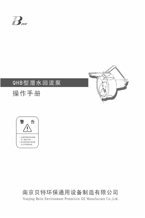
贝特技术专注环保前言前言感谢您选用“贝特”产品,本手册仅适用于本公司生产的潜水回流泵。
该产品依据企业标准“Q/320116BTHB04-2015标准”进行生产。
在安装和使用之前,请仔细阅读本手册。
若您不遵守本手册的说明而造成的人身伤害、机器损坏及其他财物损失我们将不承担责任。
如有疑问,请与我们联系,我们将及时、热情地为您提供服务。
本手册主要对潜水回流泵的结构特征、工作原理、安装与调试、使用与维护等方面作出说明。
本手册适用于潜水回流泵系列产品以及用户特殊定制的其它规格的同类产品可参照使用。
本手册中出现的产品外观图或其他图例或菜单屏幕等若与实际产品有所不同,使用时以实际产品为准。
公司的产品技术会不断创新,产品手册也会随之更改。
以后的所有更改,均不另行通知。
1贝特技术专注环保2贝特技术专注环保目录目录1安全说明 (2)1.0概述 (2)1.1运输与储存 (3)1.2安装与调试 (3)1.3使用与维护保养 (3)2用途 (4)3型号表示示例 (4)4设备结构 (4)4.1主机 (4)4.2安装系统 (5)4.3电控 (6)4.4安装附件 (6)5设备安装 (6)6设备调试 (9)7维护与保养 (10)附表1、维修记录表 (11)附表2、顾客满意度调查表 (13)3贝特技术专注环保4贝特技术专注环保设备启动前注意事项1设备启动前注意事项1.在启动潜水回流泵前,应用0—500V 兆欧表检查定子绕组绝缘情况。
2.检查所用电源、电压频率是否与标牌所示相符合。
3.请勿将潜水回流泵电线接入无任何保护装置电源(会引起缺相、过载烧毁电机)请参照其接线方法。
4.检查叶桨运转方向,从叶桨向电机端看叶桨为逆时针方向转动。
如果转向不对,应调换三相中任意两相接线位置,以获得正确的运转方向。
注意安全,避免叶桨伤人。
5.检查接地线是否正确可靠的接地。
6.严禁无水运转。
7.严禁将潜水回流泵的电缆头浸入水中。
8.在运输安装过程中,严禁使用主机电缆起吊或悬挂主机。
Parker Hannifin 公司海豹泵分区值块说明说明书

Bulletin HY14-2712-B1/USSeries V70 and V90Directional ControlValves For Open Center,Power-Beyond & Closed Center SystemsEffective:February 1, 2004Supersedes:Cat. No. GPD-1425 dated 8/97Specifications ➀ The minimum flow through a valve assembly is determined by the maximum pressure drop acceptable to the application.•Low force required to actuate spool •Extra fine metering •Low open center and loop pressure drops •SAE 4-bolt split flange or SAE straight thread porting •All ports will accommodate ORFS fittingsFeaturesDESCRIPTIONPERFORMANCEINLET COVERSOUTLET COVERWORK SECTIONSSPOOL OPTIONSSPOOL POSITIONERSSPOOL POSITIONERSDIMENSIONSDIMENSIONS ARE IN INCHES (MILLIMETERS) AND ARE FOR REFERENCE ONLY.Parker Hannifin CorporationHydraulic Valve Division 11ORDERING CODEBulletin HY14-2712-B1/US,3C, 3/04, PHD Copyright 2004, Parker Hannifin Corporation, All Rights ReservedFAILURE OR IMPROPER SELECTION OR IMPROPER USE OF THE PRODUCTS AND/OR SYSTEMS DESCRIBED HEREIN OR RELATED ITEMS CAN CAUSE DEATH, PERSONAL INJURY AND PROPERTY DAMAGE.This document and other information from Parker Hannifin Corporation, its subsidiaries and authorized distributors provide product and/or system options for further investigation by users having technical expertise. It is important that you analyze all aspects of your application and review the information concerning the product or system in the current product catalog. Due to the variety of operating conditions and applications for these products or systems, the user, through its own analysis and testing, is solely responsible for making the final selection of the products and systems and assuring that all performance, safety and warning requirements of the application are met.The products described herein, including without limitation, product features, specifications, designs, availability and pricing, are subject to change by Parker Hannifin Corporation and its subsidiaries at any time without notice.WARNINGThe items described in this document are hereby offered for sale by Parker Hannifin Corporation, its subsidiaries or its authorized distributors. This offer and its acceptance are governed by the provisions stated in the "Offer of Sale".Offer of SaleParker Hannifin Corporation Hydraulic Valve Division 520 Ternes Avenue Elyria, Ohio, USA 44035Tel:(440) 366-5200Fax:(440) /hydraulicvalve。