深深宝A9500万挂牌 转让深圳百事可乐10%股权
三垦电气 SSC9500 应用说明书

/ / / / / / / / / / / / / / / / / 目次/ / / / / / / / / / / / / / / /1.概要 (3)2.特点 (3)3.外形图(DIP16) (4)4.IC构成和各端子功能 (5)5.电气特性......................................................................................................................6~8 6.应用电路例 (9)7.各端子功能····················································································································10~197.1Vc1端子(2号端子)···························································································10~117.2Rv端子(8号端子) (12)7.3 FB/OLP端子 (3号端子) ···················································································12~147.4Css端子 (5号端子) (15)7.5Vsen端子 (1号端子) (15)7.6 Vc2端子 (9号端子) (16)7.7 OC端子 (6号端子)······························································································17~187.8RC端子 (7号端子)······························································································18~19 8.设计上的注意点············································································································19~208.1有关周边元器件 (19)8.2有关基板设计注意点 (19)8.3有关电源安装設計注意点 (20)各端子功能端子标号Terminal No.记号Symbols名称Descriptions功能Functions1 Vsen 输入(AC line)电压检测端子输入(AC line)电压检测端子图 Vc1 电压 电路电流图 启动时Vc1端子电压波形图7-6 死区时间自动调整功能动作波形SSC9500 Application Note August, 2007- Ver. 0.1FMB-26LSSC9500 Application Note August, 2007- Ver. 0.1。
sv9500系统介绍

SV9500产品介绍恩益禧数码应用产品贸易(上海)有限公司 1 / 32SV9500系统介绍恩益禧数码应用产品贸易(上海)有限公司目录1概述 (4)1.1SV9500 (4)1.2继承性 (5)1.3概要 (5)2优点 (6)2.1解决方案的核心 (6)2.2容量 (6)2.3存活性 (7)2.4 继承性 (7)2.5 功能选项 (7)2.6 系统软件升级 (8)2.7 IP终端 (8)3系统能力 (9)3.1公众网络连接 (9)3.2传统模拟设备连接 (9)3.3SIP能力 (9)3.4话务处理能力 (10)3.5TDM能力 (10)4网关 (11)4.1高密度网关 (11)4.27RU 高密度网关 (11)4.3TDM交换单元(TSW-BOX) (12)4.4TDM交换单元(TSWR) (12)5IP媒体设备 (13)5.1概述 (13)5.2UG50 (13)5.3语音会议服务器 (13)5.4SIP中继网关 (14)5.5多用途机框 (14)6应用 (16)6.1概述 (16)6.2OAI(开放应用接口) (16)6.3MCI(消息中心接口) (17)6.4SMDR(呼叫详细信息记录) (18)6.5联络中心 (18)6.6酒店应用 (18)7终端 (22)7.1概述 (22)7.2DT&SP (22)7.3SP350软电话 (24)8话务台 (25)8.1桌面话务台 (25)8.2PC话务台(UA5200/UA5300) (25)9可靠性和冗余 (27)9.1系统可靠性 (27)9.2系统冗余 (27)10管理 (29)10.1简介 (29)10.2数据库信息 (29)10.3SNMP (30)10.4语音质量管理 (30)11技术规范 (32)1 概述1.1 SV9500SV9500 IP通信服务平台-NEC SV家族最年轻的成员,支持语音,统一通信和移动解决方案。
面向容易和高效扩展,SV9500满足大型企业的需求,在网络环境下提供多达192000端口。
智能位置传感器 SPTM-5V 系列说明书

Transmitter PRODUCT MANUAL PositionSmartSPTM-5V SERIESVERSION 1.01Contents1. Introduction (3)1.1 General information for the users (3)1.2 Manufacturer Warranty (3)1.3 Explosion Proof Warning (3)2. Product Description (4)2.1 General (4)2.2 Main Features and Functions (4)2.3 Label Description (4)2.4 Product Number (5)2.5 Product Specification (5)2.6 Parts and Assembly (6)2.7 Dimension – SPTM-5VL (7)2.8 Dimension – SPTM-5VR (7)3. Installation (8)3.1 Safety (8)3.2 SPTM-5VL Installation (8)3.3 SPTM-5VR Installation (9)4. Connection– Power (10)4.1 Safety (10)5. Adjustment (11)5.1 Setting Point Switch (11)5.2 Adjustment - Calibration (11)5.3 Adjustment – Potentiometer (11)6. Troubleshooting (12)1. Introduction1.1 General Information for the usersThank you for purchasing Young Tech Co., Ltd products. Each product has been fully inspected after its production to offer you the highest quality and reliable performance.Please read the product manual carefully prior to installing and commission the product.For the safety, it is important to follow the instructions in the manual. Young Tech Co., Ltd will not be responsible for any damages caused by user’s negligence.The manual should be provided to the end-user.Any modifications or repairs to the product may only be performed if expressed in this manual.The manual can be altered or revised without any prior notice. Any changes in product’s specification, design, and/or any components may not be printed immediatelybut until the following revision of the manual.The manual should not be duplicated or reproduced for any purpose without prior approval from Young Tech Co., Ltd, Gimpo-si, South Korea.Warranty1.2 ManufacturerFor the safety, it is important to follow the instructions in the manual. Manufacturer will not be responsible for any damages caused by user’s negligence.Manufacturer will not be responsible for any damages or accidents as a result of any alteration or modification of the product and its parts. If any alteration or modificationsare necessary, please contact Young Tech Co., Ltd directly.Manufacturer warrants the product from the date of original purchase of the product for one (1) year, except as otherwise stated.Manufacturer warranty will not cover products that have been subjected to abuse, accidents, alterations, modifications, tampering, negligence, misuse, faulty installation,lack of reasonable care, repair or service in any way that is not contemplated in thedocumentation for the product, or if the model or serial number has been altered,tampered with, defaced or removed; damages that occurs in shipment, due to act ofGod, failure due to power surge, or cosmetic damage. Improper or incorrectlyperformed maintenance will void this limited warranty.For detailed warranty information, please contact Young Tech Co., Ltd – South Korea.1.3 Explosion Proof WarningPlease ensure the unit is being used and installed within the explosion proof certified environment.SPTM-5V series explosion proof grades are Ex ia IIC T6.Certified ambient temperature is -20’C ~ 60’C. The product should be used in certifiedambient temperature. If the field is not explosion proof area and does not requireexplosion proof, the product can be used in temperature range of -40’C ~ 85’C. LCDoperation temperature range is –30’C ~ 85’C.Barrier must be installed with below specificationUi =28V, li =47mA, Pi =437mA, Li =0.3μH, Ci = 56.5nFThe product must be grounded according to explosion proof procedure.2. Product Description2.1 GeneralSPTM-5V series is 2 wire type transmitter with in-built micro-processor which transmits DC 4~20mA signal according to changes in valve or damper position.2.2 Main Features and FunctionsDesigned to be Ex ia IIC T6 explosion proof grades.Economical price and long product life time.Very easy and simple calibration.LCD displays current output signal.Description2.3 LabelFig. 1: SPTM-5V Body LabelA. Model Number: Indicates model number.B. Explosion Proof: Indicates certified explosion proof grade.C. Input.: Indicates input rotation angleD. Output: Indicates output signal rangeE. Lot No.: Indicates unique lot number** SPTM-5V series’ KCs certification conforms Ministry of Employment and Labor announcement article No. 2010-36.2.4 ProductNumber2.5 ProductSpecificationModel SPTM-5VL SPTM-5VR Input Type 2 WireInput Signal0 ~ 30 degrees 0 ~ 90 degreesOutput Signal 4 ~ 20mA DCLoad Resistance Max.600 Ω / 28V DCSupply Voltage9 ~ 28V DCNoise Range50mV p.p.Conduit Entry PF 1/2 (G 1/2)Enclosure IP 67Explosion Proof Ex ia IIC T6 (KCs)Ambient Temp.Operating: -40’C ~ 85’C Explosion Proof: -20’C ~ 60’C LCD Operating: -30 ~ 85’CLinearity ± 1% F.S. Hysteresis0.2% F.S Sensitivity ± 0.2% F.S. Material Aluminum Diecasting Weight 0.6 kgAssemblyand2.6 Parts2.7 Dimension – SPTM-5VL2.8 Dimension – SPTM-5VR3. Installation3.1 SafetyWhen installing a unit, please ensure to read and follow safety instructions.Check unit’s specification and ensure to use as specified.Follow other explosion proof procedures and safety precautions.Use bypass valve or other supportive equipment to avoid entire system “shut down”.Make sure all input and supply pressure to valve, actuator, and other related devices must be turned off.Installation3.2 SPTM-5VL1. Proper bracket must be made in order to adapt SPTM-5V on the actuator yoke.Please consider following important points when a bracket is being designed.- SPTM-5V feedback lever must be parallel to the ground at 50% of the valve stroke.- Feedback lever connection with the pin of the actuator clamp should be installed in such a way that the valve stroke length coincides with the corresponding figure of“mm marked on the feedback lever. Improper setting may cause poor linearity.2. Assemble the SPTM-5V with the bracket made in previousstep by fastening the bolts. Please refer to the backside ofthe SPTM-5V for size of the bolts. The standard bolt size isM8 x 1.25P.3. Attach SPTM-5V with the bracket to the actuator yoke – DONOT TIGHTEN COMPLETELY.4. Connect SPTM-5V’s feedback lever to the actuator clamp. The hole gap on thefeedback lever is 6.5mm. The connection pins outer diameter should be less than6.3mm.5. Connect supply pressure to the actuator temporarily. Supply enough supply pressure tothe actuator in order to position the actuator clamp at 50% of the total valve stroke.6. Insert connection pin into the feedback lever. The pin should be inserted when theactuator clamp is at 50% of the total valve stroke.7. Check if the feedback lever is parallel to the ground at 50% of thevalve stroke. If it is not parallel, adjust the bracket or feedback linkbar to make parallel. Improper installation may cause poorlinearity.8. Check the valve stroke. The stroke marks are indicated on the feedback lever.Position the connection pin at the number on the feedback lever which corresponds tothe desired valve stroke. To adjust, mover the bracket or the connection pin or both.9. After installing the SPTM-5v, operate the valve from 0% to100% stroke by using direct air to the actuator. On both 0%and 100%, the feedback lever should not touch the leverstopper, which is located on the backside of SPTM-5V. If thefeedback lever touches the stopper, SPTM-5V should beinstalled further away from the yoke.Installation3.3 SPTM-5VR1. Please refer to SPTM-5VL installation section for important note for bracket design.2. There are two types of the lever – standard and NAMUR type.4. Connection – Power4.1 SafetyWhen installing a unit, please ensure to read and follow safety instructions.When installing in hazardous and explosive gas area, conduit tube or pressure-proof packing union must be used.Please use ring-type rug to protect against vibration or any other external impact.Please use twisted cable with conductor section are 1.25mm2 and that is suitable for 600V (complying to the conductor table of NEC Article 310.) The outer diameter of thecable should be between 6.35 ~ 10mm. Use shield wire to protect against electro-magnetic field and noise.Please do not install the cable near high noise equipments, such as high-capacity transformer or motor.4.25. Adjustment5.1 Setting Point SwitchSPTM-5V series can be calibrated in 2 or 5 points setting.a) 2 Point Setting:By setting minimum and maximum points <0% and 100% of valve stroke>, in-bb) 5 Point SettingBy setting 5 points <0%, 25%, 50%, 75%, and 100%> the outputs can be set accordingly.5.2 Adjustment - Calibrationa) Input 4mA signal to the positioner to move the valve stroke to the 4mA position.b) After the valve reaches at the 4mA position, press “4mA button for 3-4 seconds. Thelamp will be lighted, and this indicates that 4mA outputfeedback position has been calibrated.c) Please repeat above step for 8mA, 12mA, 16mA, and20mA for 5 point setting. For 2 point setting, repeatabove step for 20mA only.5.3 Adjustment – PotentiometerPotentiometer is designed to output 12mA signal when the feedback lever is at 50% position.In case of dislocation of the potentiometer, please follow below procedure to re-set thepotentiometer.● Power must be turned off before adjusting potentiometer.● Please be cautious when adjusting potentiometer.● Please make sure that there is no remaining circuit on the PCB.● Please do not use excessive force when disconnecting potentiometer from the PCB.1. Locate the potentiometer under the PCB. Disconnect from the PCB. Please do not useexcessive force.2. Unfasten lock screw which locks the potentiometer gear and take out potentiometer bodyfrom the lag-gear.3. Fix the feedback lever at 50% position and measure resistance level by connecting twoprobes out of three inlets.4. Rotate pinion gear until resistance vale is about 5KΩ.5. After setting the resistance value, rotate stopper to the normal position an fasten the lockscrew.6. Reconnect potentiometer to the PCB and reinstall PCB onto SPTM-5V body.SPTM-5VR6. Troubleshooting1) SPTM-5V shows no output signal.A. Check actual input signal to SPTM-5V.B. Check power connection and + / - poles.2) Input signal value to the positioner and output signal value from SPTM-5V differsdramatically.A. Check input signal value and supply voltage. Insufficient voltage can affect input signalvalue.B. Check the installation of the positioner. If the positioner is installed improperly, pleaserefer to the positioner’s manual and re-install the positioner.C. Set the positioner’s zero and span. Inaccurate zero and span setting can lower theaccuracy and linearity.D. Check the installation of the position transmitter. If SPTM-5V is installed improperly,then refer to the manual and re-install.3) Sudden changes in SPTM-5V’s output signal value.A. Please make sure that SPTM-5V’s lever is placed at 50% point. If not, SPTM-5Vneeds to be re-installed and adjusted to be placed at the 50% point.B. Adjust the potentiometer. Potentiometer’s load resistance is 10KΩ, and it should beready at the 50% point.Manufacturer:Young Tech Co., Ltd#3022, Hagun-ri, Yangchon-myeonKimpo-si, Kyeonggi-do, 415-843South KoreaTel: +82-31-986-8545Fax: +82-31-986-2683Email: **********.krCopyright © Young Tech Co., Ltd. All Rights Reserved.。
Marlin固件全中文解析
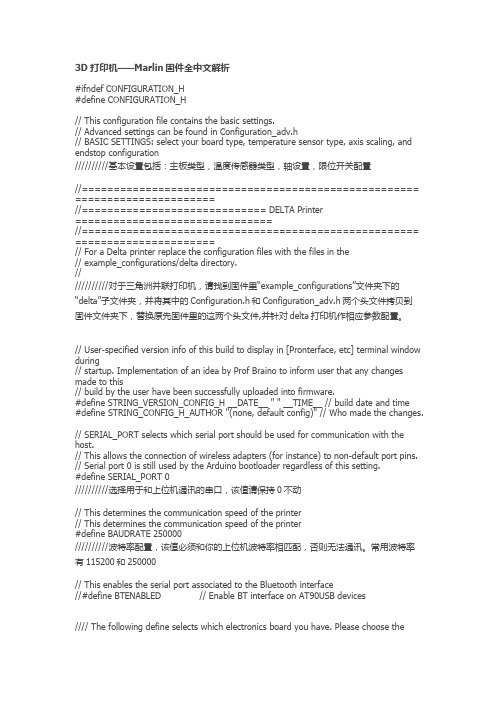
3D打印机——Marlin固件全中文解析#ifndef CONFIGURATION_H#define CONFIGURATION_H// This configuration file contains the basic settings.// Advanced settings can be found in Configuration_adv.h// BASIC SETTINGS: select your board type, temperature sensor type, axis scaling, and endstop configuration//////////基本设置包括:主板类型,温度传感器类型,轴设置,限位开关配置//===================================================== ======================//============================= DELTA Printer===============================//===================================================== ======================// For a Delta printer replace the configuration files with the files in the// example_configurations/delta directory.////////////对于三角洲并联打印机,请找到固件里“example_configurations”文件夹下的“delta”子文件夹,并将其中的Configuration.h和Configuration_adv.h两个头文件拷贝到固件文件夹下,替换原先固件里的这两个头文件,并针对delta打印机作相应参数配置。
OptiXOSN9500产品培训

学习改变命运,知 识创造未来
OptiXOSN9500产品培训
OSN 9500系统概述-网络地位
学习改变命运,知 识创造未来
OptiXOSN9500产品培训
OSN 9500系统概述-主要特性
主要特性如下: • 采用中立柱机柜 • 子架为600深,母板位于正中 • 子架正面32个都是线路槽位,且每
个槽位支持的最大业务容量为20G • 线路槽位间不存在物理上的对偶关
l 交叉板介绍 l 主控板介绍 l 时钟板介绍 l 通讯板介绍
学习改变命运,知 识创造未来
OptiXOSN9500产品培训
OSN 9500交叉单元
交叉单元类型: • SSJ1GXCH
高阶(VC4)交叉板,单板交叉容量200G,子架级交叉容量400G • SSJ1EXCH
高阶(VC4)交叉板,单板交叉容量360G,子架级交叉容量720G • SSJ1JXCL
l GE到GE业务点到点的以太网纯透明传输;
l 数据流量控制。
学习改变命运,知 识创造未来
OptiXOSN9500产品培训
学习改变命运,知 识创造未来
课程内容
第一章 产品系统概述 第二章 9500 线路单元 第三章 时钟交叉特性 第四章 机电单元
OptiXOSN9500产品培训
第三章 时钟交叉特性
Gigabit
Ethernet
GE06是OptiX OSN 9500系统中6路千兆以太网处理板。该单板主要完成6 路千兆以太光信号的光电转换、以太帧处理、映射、开销指针处理, 通过背板与主备两块交叉板连接,进行数据交换从而实现业务的调度 。
l 6路千兆以太网的接入;
l 支持1000BASE-LX/1000BASE-SX的传输方式;
中海达GPS手簿 Dolphin9500简易操作说明
目录一.开关GPS主机二.GPS工作模式的设置三.电台频道设置四.GPS主机面版灯含义五.Dolphin手簿操作说明六.架设基准站七.手簿与GPS主机的连接(蓝牙无线连接)八.手簿程序的操作流程(转换参数配合高程拟合法) 1.新建项目2.设置基准站3.断开手簿与基准站GPS主机4.添加控制点5.连接手簿与移动站GPS主机6.移动站设置7.采集碎部点坐标8.求解转换参数和高程拟合参数9.点放样10.测量成果的导出九.附录1.卫星检验2.接收机复位3.设置高程拟合模式说明4.连接程序的安装5.手簿常用快捷键功能一览表6.求解七参数的操作7.计算两点间距离8.计算校正参数9.直线放样10.HD-POWER操作程序的升级一、开关GPS主机1、按电源键1秒,开机2、按电源键3秒,关机二、控制面板按键图解主机控制面板有按键两个:F键(功能键)和电源键,指示灯3个,分别为电源、卫星、状态。
按键和指示灯的功能和含义分别是:V8 CORS RTK 系统面板控制和指示说明图2 主机控制面板按键图数据链:电台频道:控制面板操作说明:一、功能键操作说明:1、双击 F (间隔>0.2S, 小于1S), 进入“工作方式”设置,有“基站”、“移动站”、“静态”三种工作模式选择。
2、长按F大于3秒进入“数据链设置”,有“UHF”、“GSM”、“外挂”三种数据链模式选择。
3、按一次 F键, 进入“UHF电台频道”设置。
有0~9、A~F共16个频道可选。
4、轻按关机按钮,语音提示当前工作模式、数据链方式和电台频道,同时电源灯指示电池电量。
二、指示灯操作说明:1、电源灯(红色): “常亮”:正常电压:内电池>7.2V, 外电>11V“慢闪”:欠压: 内电池≤7.2V,外电≤11V“快闪”:指示电量:每分钟快闪 1~4 下指示电量2、卫星灯(绿色):“慢闪”:搜星或卫星失锁“常亮”:卫星锁定3、状态灯(红绿双色灯):绿灯:(信号灯)内置UHF移动站时指示电台信号强度外挂UHF基准站时常灭内置GSM时指示登陆(慢闪),连接上(常亮)静态时发生错误(快闪)其他状态常灭红灯:(数据灯)数据链收发数据指示(移动站只提示接收,基站只提示发射)静态采集指示二、GPS工作模式的设置目的:V8 RTK具有静态、RTK等功能,事先必须对其主机作相应的基准站、移动站、静态或GPRS设置。
UNIVERGE SV9500通信服务器数据手册说明书
Data sheetEmpowering the Smart EnterpriseThe UNIVERGE SV9500 Communications Server is a robust, feature -rich platform, perfect for geographicallydistributed enterprises and governments. With its fully integrated Unified Communications capabilities the SV9500 will empower your users, allowing them to communicate in new and exciting ways. A complete solution with video and audio conferencing, mes-saging, directory, presence, contact centre, soft phones and mobile clients.The UNIVERGE SV9500 offers:> A powerful IP communications platform with integrated Unified Communications, Mobility, and Unified Messaging.> Seamlessly mix and match IP telephony with high density traditional services. > Easy to use web based management tool for day to day moves, adds and changes.> Integration to existing corporate directories to allow automatic provisioning of phones and UC features. > The choice of deploying as a high availability appliance or as virtualised software.Taking your business communications to the next level.UNIVERGE ®SV9500COMMUNICA TIONS SERVER/univergeAbout NEC Corporation - NEC Corporation is a leader in the integration of IT and network technologies that benefit businesses and people around the world. By providing a com-bination of products and solutions that cross utilize the company's experience and global resources, NEC's advanced technologies meet the complex and ever -changing needs of its customers. NEC brings more than 100 years of expertise in technological innovation to empower people, businesses and society. For more information, visit NEC at UNIVERGE SV9500DataSheet | v.20150115NEC Corporation reserves the right to change product specifications, functions, or features, at any time, without notice. Although all efforts have been made to ensure that the contents are correct, NEC shall not be liable for any direct, indirect, consequential or incidental damages resulting from the use of the equipment, manual or any related materials. The information contained herein is the property of NEC Corporation and shall not be reproduced without prior written approval from NEC Corporation.Copyright © 2015 NEC Corporation. All rights reserved. NEC, NEC logo, and UNIVERGE are trademarks or registered trademarks of NEC Corporation that may be registered in Japan and other jurisdictions. All other trademarks are the property of their respective owners.Corporate Headquarters (Japan) NEC Corporation Americas (US, Canada, Latin America) NEC Corporation of America Asia Pacific NEC Asia Pacific .sgEMEA (Europe, Middle East, Africa) NEC Enterprise Solutions www.nec The SV9500 meets all your com-munications needs.System capacitiesOptional IP componentsAppliance redundancy options> Additional CPU for automatic failover > Additional power supply。
TSI9500 说明书
Rain 2015.07.30 9
Generate Screens 选择生成报告所使用的数据范围
Rain 2015.07.30
在您选择数据范围之后,显示如右画面。 选择通道(粒径),包括在报告中,然后按生 成…
生成报告如右图,可直接打印报告。 (报告中会对各项参数进行判定是否合格,最 后生成总的判别)
Alarms Screen 此界面可以选择你想报警的粒径通道,并
且可设置报警值。采样时,如果计数大于报警 值,这采样界面上会显示报警图标并且报警器 也会发出报警声。此时点击报警图标,报警会 解除(如果你设置了报警打印,那么此时会打 印数据,并标注出超标数值)
6
Count Mode Screen(取样模式) Automatic(自动):会根据屏幕上面设置点击 采样按钮自动进行采样。 Manual(手动):根据屏幕上面的配置,点击 采样后设备会采样一个周期后停止。 Beep(蜂鸣):选择此模式,计数器在采集到 数据后如果达到设置的最小报警值后会立刻发出 哔哔报警声。(说明待补充)
Print Setup Screen 序列号:表示用于收集数据的粒子计数器的序 列号将被打印出来。 型号名称:表示用于收集数据的粒子计数器的 型号将被打印出来。 分割线:分割线将型号名称和所有要打印的数 据进行分割显示。 差示数据的差值将被打印出来。 累积的数据将被打印。 上次校准日期:仪器校准 TSI 的时间。
2
System Setup Screen
Rain 2015.07.30
Configuration Screen 使用此屏幕设置配置参数。完成后,按确定。 Δ and Σ on Zoom:在主界面上显示累计值 和差值 Store Partial Samples:当选择时,如果该 仪器在采样周期内停止,在当前数据库中存储 部分记录。 Volume:报警音量设置。
High-SpeedPacketAccessEvolutionin3GPPRelease7
產品名稱 產品型號 WNR3500L 介面 無線區域網路標準
頻段 無線特性支援
無線加密/安全
防火牆特性支援 隱私控制和管理
管理特性支援
硬體規格 環境規範 保固維修
Wireless-N 300 千兆無線寬頻路由器(帶 USB 介面) WNR3500L 廣域網路口:1 個 10/100/1000M 埠;自我調整 區域網口:4 個 10/100/1000M 埠;自我調整 新一代 Wireless-N 技術無線區域網接入點 IEEE 802.11n version 2.0,IEEE 802.11g,IEEE 802.11b 2.4GHz 配套使用 Wireless-N 的用戶端網卡,可提供更遠的信號發射距離 同時支援飆網、MP3 下載、網路電話、檔共用、網路遊戲、高清晰度的視頻等多種應用 最高 300Mbps 的無線傳輸 64 位、128 位 WEP 有線等效加密 WPA-PSK,WPA2-PSK SSID 打開/關閉 無線局域網打開/關閉 MAC 地址認證 Wi-Fi 保護設置(WPS),一鍵加密 PIN 碼驗證 Stateful Packet Inspection (SPI) Network Address Translation (NAT) 拒絕服務(DoS)攻擊保護 Exposed Host (DMZ) 時間的使用控制 WEB 網站控制 URL 內容過濾 智慧嚮導可自動檢測 ISP 網址類別型(靜態、動態、PPPoE) 基於 Web 的圖形化使用者介面,用戶名和口令保護 共用互聯網的連接 通過 IP 地址或範圍和口令認證的遠端系統管理支持 相容所有標準的 802.11b,802.l1g 無線設備 尺寸:175 x 130 x 35mm (6.89 x 5.12 x 1.38 英寸) 重量(含電源適配器):330g(0.72 磅) CPU:Broadcom 480 MHz MIPS® 74K CPU 快閃記憶體:8M RAM:64M 工作溫度:0°~40°C(32°~104°F) 工作環境濕度:90%,無冷凝 1年
Fluke 9500B Users Manual Supplement说明书
Manual SupplementManual Title: 9500B Users Supplement Issue: 2Part Number: 1625019 Issue Date: 9/06Print Date: October 2005 Page Count: 6Version 11This supplement contains information necessary to ensure the accuracy ofthe above manual.© 2006 Fluke Corporation. All rights reserved.x9500B Users Manual SupplementChange #1On page 8-3, add the following section to the bottom of the page:8.2.4 Active HeadsA range of Active Heads are available for the 9500B Oscilloscope calibrator. Active head connectorwear can seriously impact product specifications. Fluke recommends that connectors are inspected for wear or damage before use. The recommended interval for connector replacement based on averageuse is every two years, and once per year for Active heads with higher than average use.Contact a Fluke authorized service center for replacement. Attempts to change connectors without the correct tools, training or calibration system is not recommended.On page 10.6-1, under 9510/9530/9550/9560 Head Calibration Procedures replace the second paragraph with the following:The list of topics above are placed in the order in which the 9500B Head functions should becalibrated. Head calibration requires the use of a verified 9500B Mainframe.On page 10.6-6, under 10.6.2.8 Calibration Procedure, add the following note:NoteThe 9560 can only operate with the 9500B mainframe. It also requires the 9500B/3200frequency configuration. The 9500 oscilloscope calibrator is not compatible with the9560. Neither are mainframes configured with frequency bandwidth less than 3200 MHz On page 10.6-7, under 10.6.3.1 Summary, replace the paragraph with the following: The Edge Function is calibrated by applying risetime corrections in the sequences given in paras10.6.3.4 through 10.6.3.12. Equipment requirements are given in para 10.6.3.2; para 10.6.3.3describes the Calibration Setup.Under 10.6.3.2 Equipment Requirements, replace the entire section with the following: •The UUT Active Head, connected to a verified Model 9500B Mainframe.•High-bandwidth sampling oscilloscope with bandwidth ≥6GHz for Risetimemeasurements.(≥20GHz for 9550 and 9560)Example: Tektronix Model TDS820 with an 80E01 series plug or Agilent 86100 DigitizingOscilloscope with a HP83489A or 54752A 50GHz Sample Head.•50e SMA – SMA co-axial ‘Trigger’ cable for trigger inputs to the high-bandwidth oscilloscope.6/06 1Manual Supplement 9500B Users2 6/06NoteCalibrating the 25 ps edge risetime of the 9550 requires the use of a short (no longer than 19.5 inches or 0.5 m), high quality, trigger cable fitted with SMA connectors. This insures a trigger signal with timing that is compatible with certain models of high speed sampling oscilloscopes.Example: Fluke part number 2636395 (supplied with 9550 or available as a spare part) • High-bandwidth coaxial attenuator may be required if 9500B edge output voltage exceedsoscilloscope input capability. Example: HP8493C opt 20 26.5GHz 3.5mm 20 dB attenuator.On page 10.6-12, under 10.6.3.12 Calibration Procedure: 25ps Edge: Speed replace the entire section with the following and add figure 10.6.3.2 and delete Table 10.6.3.9: 1.Ensure that the 9500B is connected to the oscilloscope as shown in figure 10.6.3.2 and that both instruments are powered on and warmed up. (Be sure to use the appropriate connector adapter as necessary to connect the 9550’s SMA output connector to the input connector of the oscilloscope.)Basic Setup 1.1Recommended Settings for the Sampling Oscilloscope: Channel SetupTimebaseScale 100mV/div Scale 50pS/div External Scale 0dB Reference Center Units Volts Windowing Disabled Bandwidth >20GHz Position 25 ns Offset -220 mVTrigger AcquisitionSource Channel 2 Averaging Off Slope Positive EdgeFast Edge Rise time & Fall time Measurement Procedure2.1 Press the MODE function key to access the main menu screen.2.2 From the main menu screen selection, select the MANUAL Mode of operation 2.3 Using the major function keys, select the Edge function2.4 From the screen menu, select FAST edge, followed by the 25ps pulse functionNoteOn the earlier 9500 models the 25 ps function is accessible through AUX key on the front panel.9500B Users Manual Supplement6/06 32.5 To insure the 9500B is properly configured for calibration, the TRIGGER CHANNEL and CABLESELECT must match and be different from the SIGNAL CHANNEL settings. Use the following key sequence.• Press the CHANNEL SELECT selection,• Select the proper SIGNAL CH setting as connected to the 9550 Head being calibrated – (select among CH1 to CH5 alternatives),• Press the TRIGGER CHANNEL selection,• Select the proper TRIGGER CH setting as connected with the external trigger cable – (select among CH1 to CH5 alternatives),• Confirm the wording Trigger Cable is displayed on the same channel as connected with external trigger cable. If not, then push the CABLE SELECT soft key and then match the CABLE CH setting to the correct trigger channel, and push EXIT, • Press the TRIGGER RATIO selection, and• Select the desired signal to trigger ratio (typically divide by 10).2.6 Return to the 25 ps FAST Edge screen by pressing EXIT twice2.7 Prepare to measure the 9550’s rising edge transition time. On the 9500B confirm operation with thesettings at an Amplitude of 500mV, Frequency at 1MHz, Rising Edge, and OUTPUT ON. 2.8 Adjust Oscilloscope Channel Offset and Timebase Position to center the displayed waveform. 2.9 Set the oscilloscope to average 256 samples.2.10 Select on the oscilloscope the appropriate edge transition (rising or falling) corresponding to what isbeing measured. 2.11 Record the measured edge speed as observed on the oscilloscope.2.12 The measured edge rise time value is the average of 8 separate measurements. Use the followingsequence for measuring the remaining measurement values• Press the calibrator OUTPUT OFF button, • Press the calibrator OUTPUT ON button,• Repeat the measurement and record the measured rise time.• Repeat this sequence in step 2.12 until you have recorded a total of 8 measurements.2.13 Calculate the average of these 8 measurements to a precision of 2 decimal places. This is thecalculated average rise time of the combined 9550 signal rise time and the oscilloscope response rise time. 2.14 Using the following formula, determine the 9550’s calibrated edge rise time by subtracting themeasured (or calibrated) oscilloscope measurement response rise time from your calculated average.Edge Rise Time =()()⎟⎠⎞⎜⎝⎛−22Time Rise Scope Time Rise Average Calculated2.15 Save this calculated edge rise time value for later use in calibrating the head.Manual Supplement 9500B Users2.16 Prepare to measure the 9550’s falling edge transition time by selecting the falling edge with the softkey. On the 9500B confirm operation with the settings at an Amplitude of 500mV, Frequency at1MHz, Falling Edge, and OUTPUT ON.2.17 Repeat steps 2.8 to 2.15 for the 9550’s falling edge time measurement.2.18 Turn the OUTPUT OFFSave Calibration Data to Active Head3.1 Insure the rear-panel Calibration Enable switch is in the “ENABLE” position.3.2 Press the MODE function key to access the main menu screen.3.3 Press the CALB Key on the main menu.3.4 Enable changing calibration constants by entering a valid password to access the Calibration Modedisplay screen.3.5 From the main menu screen selection, select the HEAD CAL Mode of operation.3.6 Confirm the CHANNEL SELECT settings are appropriate, then select EDGE and 25pS.3.7 Select TARGET 13.8 Refer to the Rising Edge speed as calculated in the previous section and enter this value into the edgespeed field on the display screen. Press ACCEPT CAL.3.9 Select TARGET 2 and similarly enter calculated Falling Edge speed value. Press ACCEPT CALfollowed by EXIT.3.10 Select STORE HEAD CAL and follow on screen instructions to:•Select the warning period before recalibration is due (leave at default 30 days unless otherwiserequested).•Modify the calibration due date (default 1 year from calibration date)3.11 Select STORE. Use the CHANNEL SELECT softkey to change to the appropriate Active Head tosave any unsaved data until the NONE indicator is displayed.3.12 Select EXIT to step back through the menus to the main Calibration Mode menu, then press theMODE key to exit calibration mode.3.13 Disconnect 9550 from 9500B Base Unit.4 6/069500B Users Manual Supplement Add the following Figure 10.6.3.26/06 5Manual Supplement 9500B Users6 9/06Change #2On page 7-5, under Table 7.6.1 change the following: From: Frequency Uncertainty ≥12kHz ±0.25ppm, <12kHz ±3ppmTo: Frequency Uncertainty>15kHz ±0.25ppm ±12mHz, ≤15kHz ±3ppmOn page 9-22, under Table 9.9.1.1 replace the entire Table with the following:Table 9.9.1.1. Sine Verification into 50Ω LoadPlease copy the following table. Enter the measurements in the Measured Value column on the copy and calculate asshown:。