传感器1.1
传感器概述

被测信息 敏感元件
转换元件
输出信息 信号调理电路
辅助电源Байду номын сангаас路
图1. 2 传感器组成框图
1.3 传感器分类
传感器是一门知识密集型技术,传感器原理 各异,学科广泛,种类繁多,分类方法如下:
(1)按照传感器的工作机理,可分为物理型、 化学型、生物型等。
(2)从构成原理分为结构型和物性型两类。
(3)按照物理原理分类,可分为电参量式传 感器(包括电阻式、电感式、电容式等基本型 式)、磁电式传感器(包括磁电感应式、霍尔式、 磁栅式等)、压电式传感器、光电式传感器、气 电式传感器、波式传感器(包括超声波
式、微波式等)、射线式传感器、半导体式传 感器、其他原理的传感器(如振弦式和振筒式 传感器等)。
(4)按传感器的能量转换情况,可分为能量 控制型传感器和能量转换型传感器。
(5)从传感器应用分类,分为位移传感器、 压力传感器、振动传感器、温度传感器。
另外,根据传感器输出是模拟信号还是数 字信号,可分为模拟传感器和数字传感器;根 据转换过程可逆与否,可分为双向传感器和单 向传感器等…。
传感检测技术基础
传感器概述
1.1 传感器定义
传感器是一种以一定的精确度把被测量转 换为与之有确定对应关系、便于应用的某种物 理量的测量装置
1.2 传感器构成
传感器一般是利用物理、化学和生物等学 科的某些效应或机理按照一定的工艺和结构研 制出来的。因此,传感器的组成的细节有较大
差异。但是,总的来说,传感器应由敏感元件、转 换元件和信号调理电路组成,有些包含有辅助电源 电路,如图1.2所示。
1.4 传感器技术的基本概况
1.传感器的基本要求
可靠性;静态特性;动态性能;量程;抗干扰能 力;通用性;轮廓尺寸;成本;能耗;对被测对象的 影响等。
传感器概述
第一章传感器概述1.1 传感器的组成与分类1.1.1 传感器的定义✧传感器是能感受规定的被测量并按照一定规律转换成可用输出信号的器件或装置。
通常由敏感元件和转换元件组成。
敏感元件指传感器中能直接感受被测量的部分,转换元件指传感器中能将敏感元件输出转换为适于传输和测量的电信号部分。
✧传感器输出信号有很多形式,如电压、电流、频率、脉冲等,输出信号的形式由传感器的原理确定。
1.1.2 传感器的组成✧一般讲传感器由敏感元件和转换元件组成。
但由于传感器输出信号一般都很微弱,需要有信号调节与转换电路将其放大或转换为容易传输、处理、记录和显示的形式。
因此调节信号与转换电路及所需电源都应作为传感器组成的一部分。
如图1-1所示。
传感器组成方块图✧常见的调节信号与转换电路有放大器、电桥、振荡器、电荷放大器等,他们分别与相应的传感器相配合。
1.1.3 传感器的分类✧表1-1 按输入量分类、按工作原理分类、按物理现象分类、按能量关系分类和按输出信号分类。
1.2 传感器在科技发展中的重要性1.2.1 传感器的作用与地位将计算机比喻人的大脑,传感器比喻为人的感觉器官。
功能正常完美的感觉器官,迅速准确地采集与转换获得的外界信息,使大脑发挥应有的作用。
自动化程度越高,对传感器的依赖性就越大。
1.2.2 传感器技术是信息技术的基础与支柱现代信息技术的基础是信息采集、信息传输与信息处理,它们就是传感器技术、通信技术和计算机技术。
传感器在信息采集系统中处于前端,它的性能将影响整个系统的工作状态和质量。
1.2.3 科学技术的发展与传感器有密切关系传感器的重要性还体现在已经广泛应用于各个学科领域。
如工业自动化、农业现代化、军事工程、航天技术、机器人技术、资源探测、海洋开发、环境监测、安全保卫、医疗诊断、家用电器等领域。
1.3 传感器技术的发展动向✧传感器技术共性是利用物理定律和物质的物理、化学和生物特性,将非电量转换成电量。
✧传感器技术的主要发展方向一是开展基础研究,发现新现象,开发传感器的新材料和新工艺;二是实现传感器的集成化与智能化。
传感器与检测技术第一章(共41张PPT)
1.2 检测系统的组成
信号调理模块实物图
单通道信号调理电路
1.2 检测系统的组成
3. 数据采集 基于ARM9核的嵌入式控制器
转换速度 单位次/秒; 检测是指在生产、科研、试验及服务等各个领域,为及时获得被测、被控对象的有关信息而实时或非实时地对一些参量进行定性检查和定量测
量信。噪比高,抗干扰性数能要据好。 采集是对信号调理后的连续模拟信号离散 化并转换成与模拟信号电压幅度相对应的数值信息, 状态量 颜色、透明度、磨损量、裂纹、缺陷、泄漏、表面质量等。
检测仪表和检测系统的输出信号通常有4~20 mA的电流模拟信号和脉宽调制PWM信号及串行数字通信信号等多种形式,需根据系统的具体要
求确定。
基于ARM9核的嵌入式控制器
1 传感器与检测技术的地位与作用
检测是指在生产、科研、试验及服务等各个领域,为及时获得被测、被控对象的有关信息而实时或非实时地对一些参量进行定性检查和定量测
应用领域主要有: ➢石化行业的自动 化控制。 如右图,有液位、 温度、压力等检测。
1.1 传感器与检测技术的地位与作用
➢城市生活污水处理
主要有流量 检测、液位检 测和成分量检 测。
1.1 传感器与检测技术的地位与作用
➢新型武器和装备的研制与测试
定位与导航,图为中国研制的DF-21和雷达。
1.1 传感器与检测技术的地位与作用
7.输入设备 输入设备用于输入设置参数,下达有关命
令等。最常用的输入设备是各种键盘、拨码盘、 条码阅读器等。通过网络或各种通信总线利用 其他计算机或数字化智能终端,实现远程信息 和数据输入的方式将会得到更多的应用。
1.2 检测系统的组成
键盘
触摸屏
1.2 检测系统的组成
各传感器技术参数
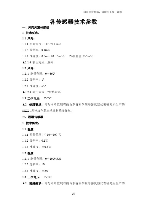
各传感器技术参数一、风向风速传感器1. 技术要求:1.1 风向:1.1.1 测量范围:(0~70)m /s1.1.2 分辨率:0.1m/s1.1.3 准确度:0.5m/s(0~5m/s),5%测量值(>5m/s)▲1.1.4 输出方式:脉冲1.2 风速:1.2..1 测量范围:0~360°1.2.2 分辨率:1°1.2.3 准确度:±5°▲1.2.4 输出方式:7位格雷码1.3 工作电压:12VDC▲2. 使用要求:需与本单位现有的山东省科学院海洋仪器仪表研究所生产的SXZ2-1型水文气象自动观测系统兼容。
二、温湿传感器1. 技术要求:1.1 温度1.1.1 测量范围:(-50~50)℃1.1.2 分辨率:0.1℃1.1.3 准确度:±0.3℃1.2 湿度1.2..1 测量范围:0~100%RH1.2.2 分辨率:1%1.2.3 准确度:±2%1.3 工作电压:12VDC▲2. 使用要求:需与本单位现有的山东省科学院海洋仪器仪表研究所生产的SXZ2-1型水文气象自动观测系统兼容。
三、水位传感器1. 技术要求:1.1 测量范围:(0~1000)cm1.2 分辨率:0.1cm1.3 准确度:±1cm1.4 工作电压:交直流两用1.4.1 交流:220V,±10%1.4.2 直流:12V,±10%▲2. 使用要求:需与本单位现有的山东省科学院海洋仪器仪表研究所生产的SXZ2-1型水文气象自动观测系统兼容。
四、温盐传感器1、技术要求:1.1 表层水温1.1.1 测量范围:-5~45℃1.1.2 分辨率:0.001℃1.1.3 准确度:±0.05℃1.1.4 传感器类型:热敏电阻1.2 表层盐度1.1.1 测量范围:0~401.1.2 分辨率:0.011.1.3 准确度:±0.031.1.4 传感器类型:电磁感应1.3 工作电压:12VDC▲2. 使用要求:需与本单位现有的山东省科学院海洋仪器仪表研究所生产的SXZ2-1型水文气象自动观测系统兼容。
传感器尺寸换算方法

1英寸=2.54厘米1/2.3英寸CCD相机传感器,对角线约1.1厘米。
宽:8.8mm;高:6.6mm。
(近似值,仅供参考)所谓的1/2.7,1/2.5,1/1.8,1/1.7,1/1.6,2/3等,里面的分子1是一个标准,分母越大,CCD越小。
所以,你说的尺寸中2/3英寸是最大的,到底有多大呢?衡量比例必须有一个标准,这个标准是沿用最早CCD应用在摄像机上的标准,指长12.8mm×9.6mm的面积,其对角线为16mm,所以1就是指的对角线为16mm。
故可以计算出1/1.8英寸的ccd:(12.8/1.8)x(9.6/1.8)=7.11mm x 5.33mm同理可以计算2/3英寸即1/1.5英寸的ccd:(12.8/1.5)x(9.6/1.5)=8.53mm x 6.4mm 有了这个标准,相信你自己就可以算出你关心的数码相机的CCD的长和宽了吧。
追问:哥们这是怎么算的啊?是分母除以分子么?回答:是按照1/1英寸为标准的对角线为16mm,而长宽比是4:3,所以标准的长宽就是12.8mm x 9.6mm。
所以别人对于数码相机的CCD大小,不需要写出具体的长、宽各是多少,而只需要给你个和标准之间差的倍数就可以了。
即1/1.8就是说标准去乘以这个系数,即长宽都乘以1/1.8就可以了。
小尺寸传感器的这种表示方式是指的对角线长度,但是不同长宽比面积是不同的,例如3:2和4:3的传感器面积,就算是同样的对角线长度面积也不同,长宽比越接近1:1面积越大常见的1/1.63英寸传感器长宽是8.07×5.56毫米,面积是44.8692平方毫米常见的1/2.3英寸传感器长宽是6.17×4.55毫米,面积是28.0735平方毫米1/1.63英寸传感器面积大约1/2.3英寸传感器的1.6倍,性能差别还是比较明显的,画质差异肉眼明显可见当然只看传感器面积也不能完全说明问题,还有像素多少问题,如果1/1.63传感器像素比1/2.3传感器高很多,可能单个像素点的宽度就差不多,那么性能也就差不多,所以单个像素点的宽度才是问题的核心不过像1/1.63英寸这种数码相机中的大尺寸传感器,一般都是高端机型使用的,强调高画质,所以不会把像素做得太高,高像素小传感器是中低端卡片机用来忽悠不了解技术细节的消费者的度为1/1.63英寸,不过这个对角线是包含了框架的尺寸的,所以实际的有效感光部分要比它小一些.然后传感器的长宽比例,以对角线长度来标注的话都是4:3的,这样你就可以计算出他们各自的实际尺寸了1英寸=25.4毫米。
微型电子机械系统传感器PCB设计与封装指南:LGA套装传感器版本1.1说明书

ANM001-MEMS S ENSOR PCB D ESIGN AND S OLDERING G UIDELINESS ENSORS WITH LGA P ACKAGEV ERSION1.1J ANUARY27,2021Revision historyAbbreviationsContents1Introduction4 2PCB Design rules4 3Guidelines for PCB Design7 4Guidelines for soldering94.1Before soldering (9)4.2After soldering (9)5Guidelines for stencil design and solder paste10 6Guidelines for process considerations10 7Important notes117.1General customer responsibility (11)7.2Customer responsibility related to specific,in particular safety-relevant ap-plications (11)7.3Best care and attention (11)7.4Customer support for product specifications (11)7.5Product improvements (12)7.6Product life cycle (12)7.7Property rights (12)7.8General terms and conditions (12)8Legal notice138.1Exclusion of liability (13)8.2Suitability in customer applications (13)8.3Usage restriction (13)9License terms for Würth Elektronik eiSos GmbH&Co.KG sensor product software and source code159.1Limited license (15)9.2Usage and obligations (15)9.3Ownership (16)9.4Disclaimer of warranty (16)9.5Limitation of liability (16)9.6Applicable law and jurisdiction (16)9.7Severability clause (17)9.8Miscellaneous (17)1This and general guidelines for solder-ing and sensor products with an LGA 2PCB231. Solder mask opening2. PCB land3. Sensor package footprintFigure 1:PCB land and solder mask recommendations for sensors with LGApackageTable 1:PCB land design dimensionsT able 2:Solder mask opening dimensionsMEMS SensorVia structureunderneath thesensor beneath the sensor LGA PackageFigure2:Incorrect PCB designMEMS SensorViaLGA PackageFigure3:Correct PCB designScrew holeScrew holeFigure4:Components inside sensor keep out area Screw holeScrew holeFigure5:Components outside sensor keep out area3•Therecommended.Please refer to•It is Anystructure underneath the•The as possible.Symmetry and which leads to better control•Screw the sensor is highly rec-•We recommend to separate digital ground from analog ground in the PCB,if enough s-pace or layer is available.The relatively large,sharp pulses of digital current transitions might affect the precise analog signals if the two signals are not separated.footprintCopper traces connectingsensor padsFigure6:Asymmetrical trace and sensor pad connectionsInformation of the PCB design and soldering processes provided in this docu-ment is considered for use as a reference.PCB land design and connecting traces should be designed symmetricallyfootprintCopper traces connectingsensor padsFigure7:Symmetrical trace and sensorpad connectionsFor sensor specific information please refer to corresponding data sheet of the product.4Guidelines for solderingThe following soldering guidelines should be taken into consideration for a common PCB design and industrial practices.4.1Before soldering•Routing traces and vias below the sensor should be avoided.The active signals that are routed under may interfere with the MEMS sensor,which will affect the sensor performance.•It is not necessary to have large traces on VDD/GND line,as the power consumption of the MEMS sensors are very low.•For best performance of the sensor,design a ground plane under the sensor in order to reduce the PCB signal noise from the board.•The placement of the MEMS sensor on the PCB should avoid locations in close prox-imity to heat sources e.g.microprocessors,batteries,graphic controllers etc.•Push-buttons,screws and PCB anchor points can produce mechanical stress onto the PCB,hence the sensor placement close to these components should be avoided.•PCB bending will induce mechanical stress to the sensor therewith influence the sen-sor performance.4.2After soldering•In general,high-amplitude resonant vibrations of the PCB should be avoided.It could possibly damage the MEMS structure.•The thickness of solder paster must be uniform to reduce the inconsistent stress on the sensor.•Solder paste must be as thick as possible to reduce the decoupling stress and to avoid the PCB solder mask touching the device package.5Guidelines for stencil design and solder pasteFor proper mounting process of the MEMS sensor,thickness and soldering paste pattern are very important.•Stencil thickness of90-150µm(3.5-6mils)is recommended for screen printing.•Stainless steel stencils are recommended for solder paste application.•The signal pad openings of the stencil should be between70%and90%of the PCB pad area.•It is recommended that for better solder paste release,the aperture walls should be trapezoidal and the corners rounded.•The stencil and printed circuit assembly should be aligned to within25µm(1mil) before applying the solder paste.6Guidelines for process considerations•T o reduce the residual stress on the components,the recommended ramp-down tem-perature slope should not exceed-3°C/s.•LGA packages show metal traces on the side of the package,hence no solder material reflow on the side of the package is allowed.•Thefinal volume of the solder paste applied to a single PCB land should be less than 20%of the volume of the solder paste of all pads of one device.•It is not possible to define a specific soldering profile only for the sensors.The sol-dering profile depends on the number,size and placement of the components in the application board.•Customer should use a time and temperature reflow profile based on PCB design and manufacturing knowledge.•No-clean solder paste is recommended for assembly of the MEMS sensor to prevent further cleaning steps.•Sensor with opening surface on top should be handled carefully.Do not pick the com-ponent with vacuum tools which make direct contact with the opening of the sensor.It is recommended to use a standard pick and place process and equipment.Do not use the hand soldering process.7Important notesThe following conditions apply to all goods within the sensors product range of Würth Elek-tronik eiSos GmbH&Co.KG:7.1General customer responsibilitySome goods within the product range of Würth Elektronik eiSos GmbH&Co.KG contain statements regarding general suitability for certain application areas.These statements about suitability are based on our knowledge and experience of typical requirements con-cerning the areas,serve as general guidance and cannot be estimated as binding statements about the suitability for a customer application.The responsibility for the applicability and use in a particular customer design is always solely within the authority of the customer.Due to this fact,it is up to the customer to evaluate,where appropriate to investigate and to decide whether the device with the specific product characteristics described in the product speci-fication is valid and suitable for the respective customer application or not.Accordingly,the customer is cautioned to verify that the documentation is current before placing orders. 7.2Customer responsibility related to specific,in particularsafety-relevant applicationsIt has to be clearly pointed out that the possibility of a malfunction of electronic components or failure before the end of the usual lifetime cannot be completely eliminated in the current state of the art,even if the products are operated within the range of the specifications. The same statement is valid for all software and software parts contained in or used with or for products in the sensor product range of Würth Elektronik eiSos GmbH&Co.KG. In certain customer applications requiring a high level of safety and especially in customer applications in which the malfunction or failure of an electronic component could endanger human life or health,it must be ensured by most advanced technological aid of suitable design of the customer application that no injury or damage is caused to third parties in the event of malfunction or failure of an electronic component.7.3Best care and attentionAny product-specific data sheets,manuals,application notes,PCN’s,warnings and cau-tions must be strictly observed in the most recent versions and matching to the products revisions.This documents can be downloaded from the product specific sections on the wireless connectivity and sensors homepage.7.4Customer support for product specificationsSome products within the product range may contain substances,which are subject to re-strictions in certain jurisdictions in order to serve specific technical requirements.Necessary information is available on request.In this case,thefield sales engineer or the internal sales person in charge should be contacted who will be happy to support in this matter.7.5Product improvementsDue to constant product improvement,product specifications may change from time to time. As a standard reporting procedure of the Product Change Notification(PCN)according to the JEDEC-Standard,we inform about major changes.In case of further queries regarding the PCN,thefield sales engineer,the internal sales person or the technical support team in charge should be contacted.The basic responsibility of the customer as per section7.1 and7.2remains unaffected.The sensor driver software¨Sensor SDK¨and it’s source codes are not subject to the Prod-uct Change Notification information process.7.6Product life cycleDue to technical progress and economical evaluation we also reserve the right to discontin-ue production and delivery of products.As a standard reporting procedure of the Product Termination Notification(PTN)according to the JEDEC-Standard we will inform at an early stage about inevitable product discontinuance.According to this,we cannot ensure that all products within our product range will always be available.Therefore,it needs to be verified with thefield sales engineer or the internal sales person in charge about the current product availability expectancy before or when the product for application design-in disposal is con-sidered.The approach named above does not apply in the case of individual agreements deviating from the foregoing for customer-specific products.7.7Property rightsAll the rights for contractual products produced by Würth Elektronik eiSos GmbH&Co.KG on the basis of ideas,development contracts as well as models or templates that are subject to copyright,patent or commercial protection supplied to the customer will remain with Würth Elektronik eiSos GmbH&Co.KG.Würth Elektronik eiSos GmbH&Co.KG does not warrant or represent that any license,either expressed or implied,is granted under any patent right, copyright,mask work right,or other intellectual property right relating to any combination, application,or process in which Würth Elektronik eiSos GmbH&Co.KG components or services are used.7.8General terms and conditionsUnless otherwise agreed in individual contracts,all orders are subject to the current ver-sion of the"General Terms and Conditions of Würth Elektronik eiSos Group",last version available at .8Legal notice8.1Exclusion of liabilityWürth Elektronik eiSos GmbH&Co.KG considers the information in this document to be correct at the time of publication.However,Würth Elektronik eiSos GmbH&Co.KG re-serves the right to modify the information such as technical specifications or functions of its products or discontinue the production of these products or the support of one of these products without any written announcement or notification to customers.The customer must make sure that the information used corresponds to the latest published information.Würth Elektronik eiSos GmbH&Co.KG does not assume any liability for the use of its products. Würth Elektronik eiSos GmbH&Co.KG does not grant licenses for its patent rights or for any other of its intellectual property rights or third-party rights.Notwithstanding anything above,Würth Elektronik eiSos GmbH&Co.KG makes no repre-sentations and/or warranties of any kind for the provided information related to their accuracy, correctness,completeness,usage of the products and/or usability for customer applications. Information published by Würth Elektronik eiSos GmbH&Co.KG regarding third-party prod-ucts or services does not constitute a license to use such products or services or a warranty or endorsement thereof.8.2Suitability in customer applicationsThe customer bears the responsibility for compliance of systems or units,in which Würth Elektronik eiSos GmbH&Co.KG products are integrated,with applicable legal regulations. Customer acknowledges and agrees that it is solely responsible for compliance with all le-gal,regulatory and safety-related requirements concerning its products,and any use of Würth Elektronik eiSos GmbH&Co.KG components in its applications,notwithstanding any applications-related in-formation or support that may be provided by Würth Elektron-ik eiSos GmbH&Co.KG.Customer represents and agrees that it has all the necessary expertise to create and implement safeguards which anticipate dangerous consequences of failures,monitor failures and their consequences lessen the likelihood of failures that might cause harm and take appropriate remedial actions.The customer will fully indemnify Würth Elektronik eiSos GmbH&Co.KG and its representatives against any damages arising out of the use of any Würth Elektronik eiSos GmbH&Co.KG components in safety-critical applications.8.3Usage restrictionWürth Elektronik eiSos GmbH&Co.KG products have been designed and developed for usage in general electronic equipment only.This product is not authorized for use in equip-ment where a higher safety standard and reliability standard is especially required or where a failure of the product is reasonably expected to cause severe personal injury or death, unless the parties have executed an agreement specifically governing such use.Moreover, Würth Elektronik eiSos GmbH&Co.KG products are neither designed nor intended for use in areas such as military,aerospace,aviation,nuclear control,submarine,transportation (automotive control,train control,ship control),transportation signal,disaster prevention, medical,public information network etc.Würth Elektronik eiSos GmbH&Co.KG must beinformed about the intent of such usage before the design-in stage.In addition,sufficient reliability evaluation checks for safety must be performed on every electronic component, which is used in electrical circuits that require high safety and reliability function or perfor-mance.By using Würth Elektronik eiSos GmbH&Co.KG products,the customer agrees to these terms and conditions.9License terms for Würth Elektronik eiSosGmbH&Co.KG sensor product software and source codeThis License terms will take effect upon the purchase and usage of the Würth Elektronik eiSos GmbH&Co.KG sensor products.Y ou hereby agree that this license terms are appli-cable to the product and the incorporated software,firmware and source codes(collectively, "Software")made available by Würth Elektronik eiSos in any form,including but not limited to binary,executable or source code form.The software included in any Würth Elektronik eiSos sensor product is purchased to you on the condition that you accept the terms and conditions of this license terms.Y ou agree to comply with all provisions under this license terms.9.1Limited licenseWürth Elektronik eiSos hereby grants you a limited,non-exclusive,non-transferable and royalty-free license to use the software and under the conditions that will be set forth in this license terms.Y ou are free to use the provided software only in connection with one of the products from Würth Elektronik eiSos to the extent described in this license terms.Y ou are entitled to change or alter the source code for the sole purpose of creating an ap-plication embedding the Würth Elektronik eiSos sensor product.The transfer of the source code to third parties is allowed to the sole extent that the source code is used by such third parties in connection with our product or another hardware provided by Würth Elektronik eiSos under strict adherence of this license terms.Würth Elektronik eiSos will not assume any liability for the usage of the incorporated software and the source code.Y ou are not entitled to transfer the source code in any form to third parties without prior writ-ten consent of Würth Elektronik eiSos.Y ou are not allowed to reproduce,translate,reverse engineer,decompile,disassemble or create derivative works of the incorporated software and the source code in whole or in part. No more extensive rights to use and exploit the products are granted to you.9.2Usage and obligationsThe responsibility for the applicability and use of the Würth Elektronik eiSos sensor product with the incorporated software in a particular customer design is always solely within the authority of the customer.Due to this fact,it is up to you to evaluate and investigate,where appropriate,and to decide whether the device with the specific product characteristics de-scribed in the product specification is valid and suitable for your respective application or not.Y ou are responsible for using the Würth Elektronik eiSos sensor product with the incorporat-ed software in compliance with all applicable product liability and product safety laws.Y ou acknowledge to minimize the risk of loss and harm to individuals and bear the risk for failure leading to personal injury or death due to your usage of the product.Würth Elektronik eiSos’products are not authorized for use in safety-critical applications, or where a failure of the product is reasonably expected to cause severe personal injury or death.Moreover,Würth Elektronik eiSos’products are neither designed nor intended foruse in areas such as military,aerospace,aviation,nuclear control,submarine,transportation (automotive control,train control,ship control),transportation signal,disaster prevention, medical,public information network etc.Y ou shall inform Würth Elektronik eiSos about the intent of such usage before design-in stage.In certain customer applications requiring a very high level of safety and in which the malfunction or failure of an electronic component could endanger human life or health,you must ensure to have all necessary expertise in the safety and regulatory ramifications of your applications.Y ou acknowledge and agree that you are solely responsible for all legal,regulatory and safety-related requirements concerning your products and any use of Würth Elektronik eiSos’products in such safety-critical application-s,notwithstanding any applications-related information or support that may be provided by Würth Elektronik eiSos.YOU SHALL INDEMNIFY WÜRTH ELEKTRONIK EISOS AGAINST ANY DAMAGES ARISING OUT OF THE USE OF WÜRTH ELEKTRONIK EISOS’PROD-UCTS IN SUCH SAFETY-CRITICAL APPLICATIONS.9.3OwnershipThe incorporated Software created by Würth Elektronik eiSos is and will remain the exclusive property of Würth Elektronik eiSos.9.4Disclaimer of warrantyTHE SOFTWARE AND IT’S SOURCE CODE IS PROVIDED"AS IS".YOU ACKNOWL-EDGE THA T WÜRTH ELEKTRONIK EISOS MAKES NO REPRESENTATIONS AND WAR-RANTIES OF ANY KIND RELATED TO,BUT NOT LIMITED TO THE NON-INFRINGEMENT OF THIRD P ARTIES’INTELLECTUAL PROPERTY RIGHTS OR THE MERCHANTABILI-TY OR FITNESS FOR YOUR INTENDED PURPOSE OR USAGE.WÜRTH ELEKTRONIK EISOS DOES NOT WARRANT OR REPRESENT THAT ANY LICENSE,EITHER EXPRESS OR IMPLIED,IS GRANTED UNDER ANY PATENT RIGHT,COPYRIGHT,MASK WORK RIGHT,OR OTHER INTELLECTUAL PROPERTY RIGHT RELATING TO ANY COMBINA-TION,MACHINE,OR PROCESS IN WHICH THE WÜRTH ELEKTRONIK EISOS’PROD-UCT WITH THE INCORPORATED SOFTWARE IS RMA TION PUBLISHED BY WÜRTH ELEKTRONIK EISOS REGARDING THIRD-PARTY PRODUCTS OR SERVICES DOES NOT CONSTITUTE A LICENSE FROM WÜRTH ELEKTRONIK EISOS TO USE SUCH PRODUCTS OR SERVICES OR A WARRANTY OR ENDORSEMENT THEREOF.9.5Limitation of liabilityAny liability not expressly provided by Würth Elektronik eiSos shall be disclaimed.Y ou agree to hold us harmless from any third-party claims related to your usage of the Würth Elektronik eiSos’products with the incorporated software and source code.Würth Elektronik eiSos disclaims any liability for any alteration,development created by you or your customers as well as for any combination with other products.9.6Applicable law and jurisdictionApplicable law to this license terms shall be the laws of the Federal Republic of Germany. Any dispute,claim or controversy arising out of or relating to this license terms shall beresolved andfinally settled by the court competent for the location of Würth Elektronik eiSos registered office.9.7Severability clauseIf a provision of this license terms are or becomes invalid,unenforceable or null and void, this shall not affect the remaining provisions of the terms.The parties shall replace any such provisions with new valid provisions that most closely approximate the purpose of the terms.9.8MiscellaneousWürth Elektronik eiSos reserves the right at any time to change this terms at its own discre-tion.It is your responsibility to check at Würth Elektronik eiSos homepage for any updates. Y our continued usage of the products will be deemed as the acceptance of the change. We recommend you to be updated about the status of new software,which is available on our website or in our data sheet,and to implement new software in your device where ap-propriate.By ordering a sensor product,you accept this license terms in all terms.List of Figures1PCB land and solder mask recommendations for sensors with LGA package4 2Incorrect PCB design (5)3Correct PCB design (5)4Components inside sensor keep out area (6)5Components outside sensor keep out area (6)6Asymmetrical trace and sensor pad connections (7)7Symmetrical trace and sensor pad connections (8)List of Tables1PCB land design dimensions (4)2Solder mask opening dimensions (4)Monitoring & Control Automated Meter ReadingInternet of Things。
第一章传感器技术基础知识
时间常数:用时间常数τ来表征一阶传感器的动态特性。τ越小, 频带越宽。
固有频率:二阶传感器的固有频率ωn表征了其动态特性。
传感器的选用原则
与测量条件有关的因素 (1)测量的目的 (2)被测试量的选择 (3)测量范围 (4)输入信号的幅值,频带宽度 (5)精度要求 (6)测量所需要的时间
相应的响应曲线 :
传感器存在惯性,它的输出不能立即复现输入信号,而是从零开 始,按指数规律上升,最终达到稳态值。 理论上传感器的响应只在t趋于无穷大时才达到稳态值,但实际上 当t=4τ时其输出达到稳态值的98.2%,可以认为已达到稳态。 τ越小,响应曲线越接近于输入阶跃曲线, 因此,τ值是一阶传感器重要的性能参数。
测量
测量是指人们用实验的方法,借助于一定的仪器或 设备,将被测量与同性质的单位标准量进行比较,
并确定被测量对标准量的倍数,从而获得关于被测
量的定量信息。
xnu或
x——被测量值;
n x u
u——标准量,即测量单位;
n——比值,含有测量误差。
测量过程
传感器从被测对象获取被测量的信息,建立起 测量信号,经过变换、传输、处理,从而获得 被测量量值的过程。
线性传感器
S y x
灵敏度是它的静态特性的斜率,即S为常数。
非线性传感器
它的灵敏度S为一变量,用下式表示。
S dy dx
传感器的灵敏度如图1-3所示。
Y
Y
S y - y0
Yo
x
X O
a)线形传感器
Байду номын сангаас
Y dy
dx S dy dx X
传感器技术-第一讲-绪论
y
2.迟滞:传感器在正(输入 量增大)反(输入量减小)行程中
yFS ⊿Hmax
输出输入曲线不重合称为迟滞。
迟滞特性如图所示,它一般是由
实验方法测得。迟滞误差一般以
满量程输出的百分数表示,即
H 1/ 2H max / yFS 100 %
0
x
迟滞特性
式中△Hmax正反行程间输出的最大差值。迟滞误差的另一名称 叫回程误差。回程误差常用绝对误差表示。检测回程误差时, 可选择几个测试点。对应于每一输入信号,传感器正行程及反
分析传感器动态特性,必须建立数学模型。线性系统的 数学模型为一常系数线性微分方程。对线性系统动态特 性的研究,主要是分析数学模型的输入量x与输出量y之 间的关系,通过对微分方程求解,得出动态性能指标。 动态特性的传递函数在线性或线性化定常系统中是指初 始条件为0时,系统输出量的拉氏变换与输入量的拉氏 变换之比。
1.7 传感器的选用原则
一、与测量条件有关的因素 测量的目的;被测试量的选择;测量范围;输入信号的幅值, 频带宽度;精度要求;测量所需要的时间。 二、与传感器有关的技术指标 精度;稳定度;响应特性;模拟量与数字量;输出幅值;对 被测物体产生的负载效应;校正周期;超标准过大的输入信号 保护。 三、与使用环境条件有关的因素 安装现场条件及情况;环境条件(湿度、温度、振动等) 信 号传输距离;所需现场提供的功率容量。 四、与购买和维修有关的因素 价格;零配件的储备;服务与维修制度,保修时间;交货日 期。
1.5 传感器的发展趋势
传感技术的发展分为两个方面:提高与改善传感器的技术 性能、寻找新原理、新材料、新工艺及新功能等。
一、改善传感器的性能的技术途径 1.差动技术:差动技术是传感器中普遍采用的技术。它 的应用可显著地减小温度变化、电源波动、外界干扰等对传 感器精度的影响,抵消了共模误差,减小非线性误差等。不 少传感器由于采用了差动技术,还可使灵敏度增大。 2.平均技术:在传感器中普遍采用平均技术可产生平均 效应,其原理是利用若干个传感单元同时感受被测量,其输出 则是这些单元输出的平均值。 3.补偿与修正技术:针对传感器本身特性,针对传感器 的工作条件或外界环境补偿与修正,可以利用电子线路(硬件) 来解决,也可以采用微型计算机通过软件来实现。 4.屏蔽、隔离与干扰抑制。
BNI IOL-104-002-Z046 IO-Link 1.1 传感器集线器 使用说明书
BNI IOL-104-002-Z046 IO-Link 1.1 Sensor hubwith extension portUser´s GuideContents1User Instructions 4 About this Manual 4 Structure of the Manual 4 Typographical Conventions 4 Enumerations 4 Actions 4 Syntax 4 Cross references 4 Symbols 4 Abbreviations 4 Differing views 4 2Safety 5 Intended use 5 Installation and Startup 5 General Safety Instructions 5 Resistance to aggressive substances 5 Hazardous voltage 5 3First Steps 6 Connection Overview 6 Mechanical Connection 7 Electrical Connection 7 Function ground 7 IO-Link connection 7 Connecting the sensor hub 8 Module variants 8 Sensor interface 8 Extension port 8 4General Configuration 9 Extension port 9 Extension port configuration 9 Setting the serial number 54hex 9 5Configuration: "Extension Off" 10 IO-Link data 10 Process Data/Input Data 10 Parameter Data / Demand Data 11 Parameter Data / Demand Data 11 Inversion of the inputs (40hex) 12 Voltage monitoring 44hex 12 6Configuration: Extended with BNI IOL-104-002-Z046 13 IO-Link data 13 Process Data/Input Data 13 Parameter Data / Demand Data 14 Parameter Data / Demand Data 14 Inversion of the inputs (40hex) 15 Voltage monitoring 44hex 16 Setting the serial number 54hex 17 7Diagnostics 18 Error Codes/ Errors 18 Events 18 8IO-Link functions 19 IO-Link Version 1.0 / 1.1 19 Data Storage 19 Block Configuration 19 Resetting to Factory Settings 199Technical Data 20 Dimensions 20 Mechanical Data 20 Electrical Data 20 Operating conditions 20 10Function indicators 21 Function indicators 21 LED indicator module status 21 Digital LED indicators for inputs/outputs 22 Extension port 22 11Appendix 23 Type code 23 Ordering information 231User InstructionsAbout this Manual This manual describes the Balluff IO-Link I/O module, also called a sensor/actuator hub.The IO-Link protocol is used to link to the higher-level master module.In terms of function, this compact, cost-effective module is similar to a passive splitter box; itrecords digital sensor signals and transmits them over the IO-Link interface. It passescontrol signals coming over IO-Link to the connected actuators.Structure of the Manual The manual is organized so that the sections build on one another. Chapter 2: Basic safety information.……..TypographicalConventionsThe following typographical conventions are used in this manual.Enumerations Enumerations are shown as a list with an en-dash.−Entry 1.−Entry 2.Actions Action instructions are indicated by a preceding triangle. The result of an action is indicated by an arrow.➢Action instruction 1.Action result.➢Action instruction 2.Syntax Numbers:Decimal numbers are shown without additional indicators (e.g. 123), hexadecimal numbersare shown with the additional indicator hex(e.g. 3F hex).Cross references Cross references indicate where additional information on the topic can be found. Symbols Attention!This symbol indicates a safety instruction that must be followed without exception.NoteThis symbol indicates general notes.Abbreviations BNIDPPI portEMCFEIOLLSBMSBSPDU Balluff Network Interface Direct Parameter Page Digital Input Port Electromagnetic compatibility Function groundIO-LinkLeast Significant BitMost Significant BitService Protocol Data UnitDiffering views Product views and images in this manual may differ from the product described. They are intended to serve only as illustrations.2SafetyIntended use The BNI IOL-… acts as a decentral sensor input module, which is connected by an IO-Link interface to a higher-level master module.Installation and Startup Attention!Installation and startup must only be carried out by trained technical personnel. Qualified personnel are people who are familiar with installation and operation of the product and have the necessary qualifications for these tasks. Any damage resulting from unauthorized tampering or improper use voids the manufacturer's guarantee and warranty. The operator must ensure that appropriate safety and accident prevention regulations are observed.General Safety Instructions Commissioning and inspectionBefore commissioning, carefully read the user's guide.The system must not be used in applications in which the safety of persons is dependent upon proper functioning of the device.Authorized personnelInstallation and startup must only be carried out by trained technical personnel.Intended useWarranty and liability claims against the manufacturer are rendered void by: −Unauthorized tampering−Improper use−Use, installation or handling contrary to the instructions provided in this user's guideObligations of the operating companyThe device is a piece of equipment in accordance with EMC Class A. This device can produce RF noise. The operator must take appropriate precautionary measures. The device may only be used with an approved power supply. Only use approved cables. MalfunctionsIn the event of defects and device malfunctions that cannot be rectified, the device must be taken out of operation and protected against unauthorized use.Intended use is ensured only when the housing is fully installed.Resistance to aggressive substances Attention!The BNI modules generally have a good chemical and oil resistance. When used in aggressive media (eg chemicals, oils, lubricants and coolants each in high concentration (ie, low water content)) must be checked prior application-related material compatibility. In the event of failure or damage to the BNI modules due to such aggressive media are no claims for defects.Hazardous voltage Attention!Before maintenance, disconnect the device from the power supply.NoteIn the interests of product improvement, Balluff GmbH reserves the right to change the technical data of the product and the content of this manual at any time without notice.3 First StepsConnection OverviewFigure 3-1: Connection overview BNI IOL-104-002-Z0461 Ground connection2 Mounting hole3 Status LED: communication4 Part label5 Port 16 Port 37 Port 58 Port 79 Port 9 10 Port 11 11 Port 1312 Port 15, extension port13 Pin/Port LED: signal status14 Port 14 15 Port 12 16 Port 10 17 Port 8 18 Port 6 19 Port 4 20 Port 2 21 Port 0 22 IO-Link Interface12 34 5672913101112 14 151617221819208213 First StepsMechanicalConnectionThe BNI IOL modules are attached using 2 max. M4 screws and 2 washers.Electrical Connection The BNI IOL-xxx-002-Z046 modules do not require a separate supply voltage connection. Supply voltage is provided via the IO-Link interface and the higher-level IO-Link master module.Function ground The modules are equipped with a ground connection.Figure 3-3: BNI ground connection IOL...➢Connect the sensor hub module to the ground connection.NoteThe FE-connection from the housing to the machine must have low impedanceand be as short as possible.IO-LinkconnectionThe IO-Link connection is established via an M12 connector (A-coded, male).IO-Link (M12, A-coded, male)Pin Requirement1 Supply voltage controller US, +24V2 Not used3 GND, reference potential4 C/Q, IO-Link data transmission channelAttention!Overcurrent. Defective or absent fusing of the supply voltage for the sensor andactuator will result in their damage or destruction.Use a fuse or an intelligent power supply (current monitoring designed formaximum 4 A) which turns off power when overcurrent is present.3 First StepsConnecting the sensor hub ➢Connect ground conductor to the FE terminal, if available.➢Connect the incoming IO-Link cable to the sensor hub.NoteA standardized sensor cable is used to connect to the higher-level IO-Link master module. Maximum length of 20 m.Module variants Sensor hub variants Digital portBNI IOL-104-002-Z046 IN Sensor interface PortPin FunctionIN1 +24V4 In3 0VNoteFor the digital inputs, the input guideline specified in EN 61131-2, Type 3 appliesNoteUnused input port sockets must be fitted with blind caps to ensure the IP67 degreeof protection.Extension port Extension port (M8, female)The port acts like a sensor interface if the extension function is deactivated.Pin FunctionIN1 +24V4 Communication3 0VNoteA standardized sensor cable is used to connect to the device/sensor to be extended. Maximum length of 20 m.4General ConfigurationExtension port The BNI IOL-104-002-Z046 module gives you the ability to use the No. 15 slot in variousways. By default it is used as a digital input slot, where Pin 4 can be used as a digital input.This slot can be used as an extension port by making a corresponding entry in theparameter with an index of 55hex. It is thus possible to run of the following modules via SlotNo. 15:•BNI IOL-104-002-Z046Extension port configurationConfiguration Value Index 55hexBNI IOL-104-002-Z046 0BNI IOL-104-002-Z046 with BNI IOL-104-002-Z046 1NoteThe "Factory reset" command does not affect the configuration of the extension portin any way.NoteThe process data length depends on the configuration.The extension port can be configured using the parameter 55hex (see table). If data storage or validation is used, validation (identical) must be used for configuring. Depending on the system, the Device ID has to be entered (parameter data table) or the Device ID is read out from the IODD.Setting the serial number 54hex The serial number has a default value of 16x00hex.In order to use the "Identity" master validation mode, aserial number can be set using this parameter.This prevents a device from connecting to the wrong master port.5Configuration: "Extension Off"IO-Link dataProcess Data/Input Data5 Configuration: "Extension Off"/ Demand DataParameter Data/ Demand Data5 Configuration: "Extension Off"inputs (40hex)0 – Normal1 - Inverted. Array Voltagemonitoring44hexBalluff Network Interface / IO-Link6Configuration: Extended with BNI IOL-104-002-Z046IO-Link dataData/InputDataBalluff Network Interface / IO-Link6 Configuration: Extended with BNI IOL-104-002-Z046/ Demand DataParameter Data/ Demand DataBalluff Network Interface / IO-Link6 Configuration: Extended with BNI IOL-104-002-Z046the inputs(40hex)0 - Normal1 - Inverted6 Configuration: Extended with BNI IOL-104-002-Z046monitoring44hex6 Configuration: Extended with BNI IOL-104-002-Z046Setting the serial number 54hex The serial number has a default value of 16x00hex.In order to use the "Identity" master validation mode, a serial number can be set using this parameter.This prevents a device from connecting to the wrong master port.7DiagnosticsError Codes/ErrorsEvents8IO-Link functionsIO-Link Version 1.0 / 1.1 This device can be operated with an IO-Link master according to IO-Link version 1.0 and version 1.1. Version-specific functions such as data storage (version 1.1) areonly supported in combination with a suitable IO-Link master.Data Storage Each IO-Link master of IO-Link version 1.1 features data storage in which an image of the IO-Link device configuration can be stored. When a device is replaced, the stored configuration isautomatically transferred to the new device. This guarantees minimal downtime. Validation mustbe switched on in order to use the data storage. For information about the configuration of datastorage and validation, please refer to the user's guide of the respective IO-Link master.Block Configuration The device supports block configuration. This allows all parameters in a data block to be consistently imported from a controller or a configuration tool into the device.Resetting to Factory Settings The factory settings on the device can be restored by running the "restore factory settings" system command.0x82 must be written to Index 2 Subindex 0 for the command.The extension port setting is not reset in this process.9Technical DataDimensionsMechanicalDataElectrical DataOperatingconditions10Function indicatorsFunctionindicatorsLED indicator module statusCOM/ US10 Function indicatorsDigital LED indicators for inputs/outputs LED 2, Input Pin 4Extension port The table is valid if the extension port is active. If the extension port is used as a standard I, then the description from "Digital LED indicators for inputs" can be used.11AppendixType codeOrdering informationType code Order codeBNI IOL-104-002-Z046BNI00AYBNI IOL-104-002-Z046 Balluff Network InterfaceIO-Link interfaceFunctions104 = 16 inputsVariants002 = with IO-Link 1.1 extension portMechanical configurationZ046 = Die-cast zinc, matte nickel platedBus connection: 1x M12x1 external threads,16 x M8x1 internal threadBalluff GmbH Schurwaldstrasse 9 73765 Neuhausen a.d.F. Germany N o . 9 3 1 9 3 4 -7 2 6 E •0 1 . 1 3 1 0 5 7•E d i t i o n C 2 1•R e p l a c e s E d i t i o n J 1 6•S u b j e c t t o m o d i f i c a t i o n。
传感器基础知识
直接感受被测量的变化,并输出与被测量成确 定关系的某一物理量的元件。
敏感元件是传感器的核心
2024/9/29
3
转换元件: 将敏感元件输出的物理量转换成 适于传输或测量电信号的元件。
2024/9/29
4
测量电路: 将转换元件输出的电信号进行进 一步转换和处理的部分,如放大、滤波、线性 化、补偿等,以获得更好的品质特性,便于后 续电路实现显示、记录、处理及控制等功能。
y
ΔLmax
x
②过零旋转拟合
曲线过零的传感器。拟合时,使
y
ΔL1 = ΔL2 = ΔLMax
ΔL1 ΔL2
x
③端点连线拟合
把输出曲线两端点的连线作为拟合直线
y
ΔLmax x
④端点连线平移拟合
在端点连线拟合基础上使直线平移,移动距离为
原先的一半 y
ΔL2 = ΔL1 = ΔL3 = ΔLMax
ΔL3
6
2.传感器的分类
(3)按照其结构分:
传感器可分为结构型、物性型和复合型传 感器。
A、物性型传感器是依靠敏感元件材料本身物理性 质的变化来实现信号变换,如:水银温度计。
B、结构型传感器是依靠传感器结构参数的变化实 现信号变换,如:电容式传感器。
2024/9/29
7
1.1.3 传感器基本特性
传感器的基本特性是指系统的输入与输出关系特性, 即传感器系统的输出信号y(t)和输入信号(被测量) x(t)之间的关系,
2024/9/29
41
1.2 检测技术理论基础
1.2.1 检测技术
检测技术主要研究被测量的测量原理、测量方
法、检测系统和数据处理等方面的内容。
不同性质的被测量要采用不同的原理去测量, 测量同一性质的被测量也可采用不同测量原 理。
- 1、下载文档前请自行甄别文档内容的完整性,平台不提供额外的编辑、内容补充、找答案等附加服务。
- 2、"仅部分预览"的文档,不可在线预览部分如存在完整性等问题,可反馈申请退款(可完整预览的文档不适用该条件!)。
- 3、如文档侵犯您的权益,请联系客服反馈,我们会尽快为您处理(人工客服工作时间:9:00-18:30)。
感
技
术
课程性质: 课程性质:专业课 适用专业:测控技术及仪器 适用专业 学时分配:课程总学时:40学时。其中:理论课学 学时分配 时:34学时;实验学时:6学时。 教 材:朱蕴墣 主 编,国防工业出版社 参考书目: 参考书目:《传感器技术》,孙建民主编,清华大学出 版社;《传感器原理及应用》,《传感器原 理与应用技术 》,刘爱华 主编 。
2.学习的目的 2.学习的目的
掌握传感器的工作原理,在此基础上学会应用。 掌握传感器的工作原理,在此基础上学会应用。 传感器的工作原理是建立在表征它们工作特性本质的数学模型 的基础上的, 的基础上的,通过数学模型才能了解每个参数对输出特性的影 从而找到设计参数的依据, 响,从而找到设计参数的依据,找到应用时出现故障是由哪些 参数变化引起的。 参数变化引起的。
1.1.4传感器转换的常见非电量 1.1.4传感器转换的常见非电量
声学参数 机械学参数 微波参数 化学参数 光学参数 热学参数 射线参数 生物医学参数 磁学参数 流体学参数 红外线 …….
电量 传感器
第 1 章 传感器基础知识
1.1.5 测控技术研究的内容
(1)研究如何正确地获取所需的非电量变量并转换成电量的方法; )研究如何正确地获取所需的非电量变量并转换成电量的方法; (2)研究怎样用电的方法,实现各种非电量转换仪器及其自动化 )研究怎样用电的方法, 测控系统。 测控系统。
第 1 章 传感器基础知识
1.2.2 传感器的组成框图及各组成部分的作用
被测量
敏感元件
传感(转换) 传感(转换) 元件
电信号
信号调节转换电路
(非电量) 非电量)
(或其他形式) 或其他形式)
辅助电路
1)敏感元件:将被测非电量转换成容易变成电量的非电量。 敏感元件:将被测非电量转换成容易变成电量的非电量。 2)传感元件:一般情况它不直接感受被测量,将易变成电 传感元件:一般情况它不直接感受被测量, 量的非电量转换成电量(参数)。 )。如压力传感器中的应 量的非电量转换成电量(参数)。如压力传感器中的应 变片就是传感元件, 变片就是传感元件,它的作用是将弹性膜片的变形转换成 电阻值的变化。 电阻值的变化。
3.与其他课程的关系 3.与其他课程的关系
第 1 章 传感器基础知识
(1)工作原理:以各种物理、化学现象和各种效应以及电路 工作原理:以各种物理、 网络理论为基础; 网络理论为基础; (2)测量电路:以模拟电路和数字电路及电工原理为基础; 测量电路:以模拟电路和数字电路及电工原理为基础; (3)应用检测系统:以控制理论、微弱信号检测理论、误差理 应用检测系统:以控制理论、微弱信号检测理论、 论等为基础; 论等为基础; (4)智能传感器:以传感器原理、微机原理和汇编程序设计或 智能传感器:以传感器原理、 语言为基础; C++语言为基础; (5)设计制造:仪器材料学、工艺学、误差理论及制图学。 设计制造:仪器材料学、工艺学、误差理论及制图学。
1.2 传感器定义、组成框图及各组成部分的作用 传感器定义、
1.2.1 定义 狭义定义: A)狭义定义:能感受规定的被测量并按一定规律转换成可用输 出信号的器件或装置 的器件或装置。 出信号的器件或装置。 广义定义:是从一个系统中接收功率, B)广义定义:是从一个系统中接收功率,通常以另一种形式的 功率送到第二个系统中的器件。 功率送到第二个系统中的器件。 传感器的名称:变换器、发讯( 传送器、 C)传感器的名称:变换器、发讯(送)器、传送器、 换能器、探测器。 换能器、探测器。
1.2.3 传感器的分类
1)按传感器的用途分(按输入量分,按被测物理量分): )按传感器的用途分(按输入量分,按被测物理量分): 位移传感器、力传感器、温度传感器、振动传感器等; 位移传感器、力传感器、温度传感器、振动传感器等;
第 1 章 传感器基础知识
2)按照工作机理分:应变式、压电式、电容式、电感式等; 按照工作机理分:应变式、压电式、电容式、电感式等; 习惯上把以上两者合起来命名。例如:电感式位移传感器, 习惯上把以上两者合起来命名。例如:电感式位移传感器, 压电式加速度传感器。 压电式加速度传感器。 3)按被测量的转换特征分(按构成机理分):结构型、物理型。 按被测量的转换特征分(按构成机理分):结构型、物理型。 ):结构型 结构型:通过传感器结构参数的变化而实现信号的转换。 结构型:通过传感器结构参数的变化而实现信号的转换。 例如: 电容式传感器依靠极板间距离变化引起电容量的变化。 例如: 电容式传感器依靠极板间距离变化引起电容量的变化。 有些结构型传感器通过弹性敏感元件的受力变形,将力、扭矩、 有些结构型传感器通过弹性敏感元件的受力变形,将力、扭矩、 压力等转换成应变或位移, 压力等转换成应变或位移,再利用传感元件如电阻应变片等将 其转换成电量。 其转换成电量。 物理型: 物理型:利用某些材料本身的物理性质随被测量变化的特性而 实现参数的直接转换。特点是灵敏度高、响应速度快、 实现参数的直接转换。特点是灵敏度高、响应速度快、结构简 便于集成等特点。 单、便于集成等特点。
x
∆x
事物
y
被控非电量和输出非电量都是通过 传感器来完成的
β
xβ
控制框图
第 1 章 传感器基础知识
1.1.3 传感器在科学技术中的作用 通过传感器获得数据资料,建立数学模型, (1)通过传感器获得数据资料,建立数学模型,从而研究 事物的规律性。 事物的规律性。 通过传感器与计算机相连完成实验数据资料的处理。 (2)通过传感器与计算机相连完成实验数据资料的处理。 各种非电量要通过传感器变成电量来控制事物的规律。 (3)各种非电量要通过传感器变成电量来控制事物的规律。 各个领域的研究需要各种各样的传感器。 (4)各个领域的研究需要各种各样的传感器。
第 1 章 传感器基础知识
有源(能量变换型)传感器,如基于压电效应、热电效应、 有源(能量变换型)传感器,如基于压电效应、热电效应、光 电动势效应等的传感器。 电动势效应等的传感器。
7)按转换过程可逆与否分:双向传感器、单向传感器。 按转换过程可逆与否分:双向传感器、单向传感器。
1.2.4 传感器的基本技术指标要求
第 1 章 传感器基础知识
被测量
敏感元件Βιβλιοθήκη 传感(转换) 传感(转换) 元件
电信号
信号调节转换电路
(非电量) 非电量)
(或其他形式) 或其他形式)
辅助电路
3)转换电路:将电量参数转换成可用电量(电压、 转换电路:将电量参数转换成可用电量(电压、 电流、频率等)便于传输、显示、记录、处理、 电流、频率等)便于传输、显示、记录、处理、控制等应 用的量。 用的量。 4)辅助电路:提供给传感器进行非电量转换用的辅助电源。 辅助电路:提供给传感器进行非电量转换用的辅助电源。
y→ f →
因变量或像; 函数表达形式。
用框图表示自变量和因变量之间的对应关系为
x
f
y
第 1 章 传感器基础知识
数学模型 a.定义 数学模型是所研究系统(对象)的某种特征的本质的 定义:数学模型是所研究系统 定义 数学模型是所研究系统(对象) 表达式,即用数学公式(函数式、代数方程、微分方程、 表达式,即用数学公式(函数式、代数方程、微分方程、 微积分方程、差分方程等)来描述(表示、模拟) 微积分方程、差分方程等)来描述(表示、模拟)所研 究的客观对象或系统在某一方面的存在规律。 究的客观对象或系统在某一方面的存在规律。 b.步 b.步 骤
第 1 章 传感器基础知识
4.学习过程 4.学习过程
定性描述(学习传感工作原理的物理过程) 定量分析( 定性描述(学习传感工作原理的物理过程) 定量分析( 推导传感器工作原理的数学模型, 推导传感器工作原理的数学模型,分析参数对输出的影响来确定 并理解工作原理) 应用(估计应用中出现故障的原因)。 并理解工作原理) 应用(估计应用中出现故障的原因)。
静态精度; 动态性能; 1)可靠性; 可靠性; 2)静态精度; 3)动态性能; 5)抗干扰能力; 5)抗干扰能力; 6)通用性; 7)轮廓尺寸; 通用性; 轮廓尺寸; 抗干扰能力 能耗; 10)对被测对象的影响等。 9)能耗; 10)对被测对象的影响等。 4)量程; 量程; 8)成本; 成本;
数据资料
假定 物理模型
实际系统
数学模型
应用
假定
检验、 检验、修正
任何科学问题尤其是电类科学问题研究的方法都是用 数学模型来描述的。 数学模型来描述的。
第 1 章 传感器基础知识
数据资料、 1.1.2 数据资料、控制事物规律与传感器 要建立数学模型,需要获得实验数据资料, 要建立数学模型,需要获得实验数据资料,要获得准确的 数据资料其测量次数必须为无穷大,也就是要很多次测量, 数据资料其测量次数必须为无穷大,也就是要很多次测量,必 须依靠传感器自动完成。 须依靠传感器自动完成。 控制事物的规律是按照给定的规律(数学模型) 控制事物的规律是按照给定的规律(数学模型)和预定的 参数,进行自动控制,达到预期的效果,控制框图如图所示: 参数,进行自动控制,达到预期的效果,控制框图如图所示:
第 1 章 传感器基础知识
仪器仪表、自动化仪表、精密仪器专业: 非电量转换的基础; 仪器仪表、自动化仪表、精密仪器专业: 非电量转换的基础; 自动化专业:参数控制的基础; 自动化专业:参数控制的基础; 电子应用专业:参数转换的基础; 电子应用专业:参数转换的基础;
测控技术及仪器专业:主干课程。 测控技术及仪器专业:主干课程。
第 1 章 传感器基础知识
1.1 传感器在科学技术中的应用
1.1.1 数学模型的定义和工程建模 研究事物的运动规律和特点, 研究事物的运动规律和特点,通常情况下都是应用数学这个工具 • •• 建立数学模型, ,建立数学模型,一般为 • •• y = f ( x, x, x, L), x, x, x →自变量或像原;