A delithiated LiNi0.65Co0.25Mn0.10O2 electrode material A structural, magnetic and electrochemical
天津大学材料学院2019级博士申请答辩

Discharge capacity / mAh g-1 Discharge capacity / mAh g-1 Discharge capacity / mAh g-1
核层组分对双核壳结构材料性能的影响
a 200 0.1C 180
3.0 - 4.4 V
160
0.2C
140
120
100 0
NC91core NCM955core NCM811core N80core HG
200
c
180 160
140 3.0-4.4V 1C
120 100
N100core N80core N67core HG
100 0
50
100
150
Cycle / n
100
200
0
50
100
Cycle / n
80
150
0 50 100 150 200 250 300 350 400
Cycle / n
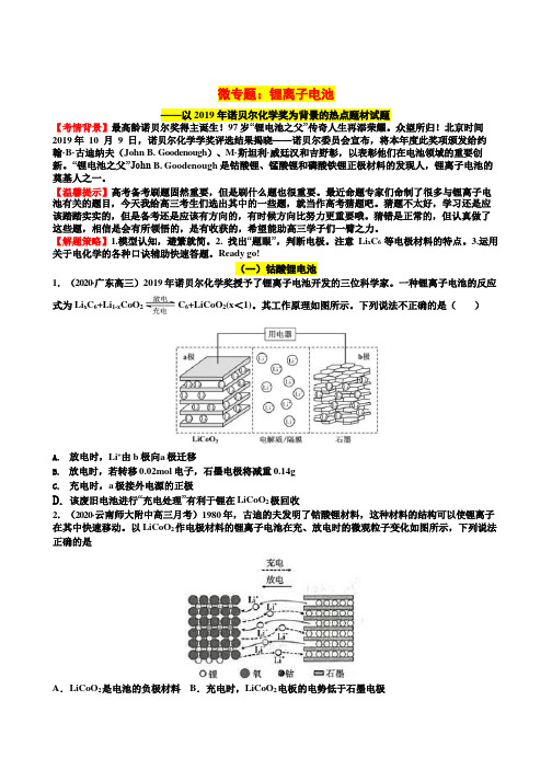
不同核壳结构正极材料在25oC的电化学性能。(a)电压范围为3-4.4 V的循环性能,(b)高电压 (3-4.5 V)循环性能,(c)电压范围3-4.4 V的高倍率(1C)长循环性能。
主要因素:易挥发易燃易爆的有机电解液是引起锂离子电池安全问题的
Nanostructured Electrode Materials for Lithium-Ion Batteries

Nanostructured Electrode Materials for Lithium -Ion BatteriesA.Manthiram and T.MuraliganthAbstract Electrochemical energy storage systems are becoming increasingly important with respect to their use in portable electronic devices,medical implant devices,hybrid electric and electric vehicles,and storage of solar and wind ener-gies.Lithium-ion batteries are appealing for these needs because of their high energy density,wide range of operating temperatures,and long shelf and cycle life. However,further breakthroughs in electrode materials or improvements in existing electrode materials are critical to realize the full potential of the lithium-ion tech-nology.Nanostructured materials present an attractive opportunity in this regard as they could offer several advantages such as fast reaction kinetics,high power density,good cycling stability with facile strain relaxation compared to their bulk counterparts.In this chapter,we present an overview of the latest progress on the nanostructured anode and cathode materials for lithium-ion batteries. IntroductionEnergy storage and production is one of the greatest challenges facing human kind in the twenty-first century.Based on moderate economic and population growth, the global energy consumption is anticipated to triple by the year2010.The rapid depletion of fossil fuel reserves,increasing fuel costs,increasing greenhouse gas emission,and global climate changes are driving the development of sustainable clean energy technologies like fuel cells,solar cells,high energy density batteries, and supercapacitors.While fuel cells and solar cells are energy conversion devices, batteries and supercapacitors are energy storage devices.Nearly one-third of the total energy consumption in the United States is by the transportation sector,and internal combustion engine based automobiles are a sig-nificant contributor of green house gas emission.Hybrid electric vehicles(HEV) and plug-in hybrid electric vehicles(PHEV)are the most viable near-term option A.Manthiram(B)Materials Science and Engineering Program,The University of Texas,Austin,TX78712,USAe-mail:rmanth@211 A.Korkin et al.(eds.),Nanotechnology for Electronics,Photonics,and RenewableEnergy,Nanostructure Science and Technology,DOI10.1007/978-1-4419-7454-9_8,C Springer Science+Business Media,LLC2010212 A.Manthiram and T.Muraliganth Fig.8.1Comparison of theenergy densities of differentbattery systemsfor transportation.Energy storage is also critical for the efficient utilization of the electricity produced from solar and wind energies.Lithium-ion batteries are appeal-ing for automobiles(HEV and PHEV)and the storage of solar and wind energy as they provide higher energy density compared to other rechargeable battery systems such as lead acid,nickel–cadmium,and nickel metal hydride batteries as seen in Fig.8.1[1].However,cost and safety are the major issues with respect to large-scale applications like automobiles and solar and wind energy storage,and they need to be adequately addressed.Lithium-Ion BatteriesRechargeable lithium batteries involve a reversible insertion/extraction of lithium ions into/from a host electrode material during the charge/discharge process.The lithium insertion/extraction process occurring with aflow of ions through the elec-trolyte is accompanied by a reduction/oxidation(redox)reaction of the host matrix assisted with aflow of electrons through the external circuit(Fig.8.2).The open-circuit voltage V oc of such a lithium cell is given by the difference in the lithium chemical potential between the cathode(μLi(c))and the anode(μLi(a))asV oc=(μLi(c)−μLi(a))/F,(8.1) where F is the Faraday constant.A schematic energy diagram of a cell at open circuit is given in Fig.8.3.The cell voltage is determined by the energies involved in both the electron transfer and Li+transfer.While the energy involved in electron transfer is related to the work functions of the cathode and the anode,the energy involved in Li+transfer is determined by the crystal structure and the coordination geometry of the site into/from which the Li+ions are inserted/extracted[2].Thermodynamic stability considerations require the redox energies of the cathode(E c)and anode8Nanostructured Electrode Materials for Lithium-Ion Batteries213 Fig.8.2Illustration of thecharge–discharge processinvolved in a lithium-ion cellconsisting of graphite as ananode and layered LiCoO2asa cathodeFig.8.3Schematic energydiagram of a lithium cell atopen circuit.HOMO andLUMO refer,respectively,tothe highest occupiedmolecular orbital and lowestunoccupied molecular orbitalin the electrolyte(E a)to lie within the band gap E g of the electrolyte,as shown in Fig.8.3,so that no unwanted reduction or oxidation of the electrolyte occurs during the charge–discharge process.With this strategy,the anode and cathode insertion hosts should have,respectively,the lowest and highest voltages vs.metallic lithium in order to maximize the cell voltage.The concept of rechargeable lithium batteries wasfirst illustrated with a transition metal sulfide TiS2as the cathode,metallic lithium as the anode,and a nonaque-ous electrolyte[3].Following the initial demonstration,several other sulfides and chalcogenides were pursued during the1970s and1980s as cathodes[4].However, most of them exhibit a low cell voltage of<2.5V vs.lithium anode.This limita-tion in cell voltage is due to an overlap of the higher valent M n+:d band with the top of the nonmetal:p band—for example,with the top of the S:3p band as shown in Fig.8.4.Such an overlap results in an introduction of holes into(or removal of electrons from)the S2−:3p band and the formation of molecular ions such as S2−2,214 A.Manthiram and T.Muraliganth Fig.8.4Relative energies ofmetal:d(for example,Co:3d)and nonmetal:p in(a)asulfide and(b)an oxidewhich in turn leads to an inaccessibility of higher oxidation states for M n+in a sul-fide Li x M y S z.The stabilization of higher oxidation state is essential to maximize the cell voltage.Recognizing this difficulty with chalcogenides,Goodenough’s group at the University of Oxford focused on oxide cathodes during the1980s[5–7].The location of the top of the O2−:2p band much below the top of the S2−:3p band and a larger raising of the M n+:d energies in an oxide compared to that in a sulfide due to a larger Madelung energy(Fig.8.4)make the higher valent states accessible in oxides. For example,while Co3+can be readily stabilized in an oxide,it is difficult to sta-bilize Co3+in a sulfide since the Co2+/3+redox couple lies within the S2−:3p band as seen in Fig.8.4.Accordingly,several transition metal oxide hosts crystallizing in a variety of structures(two-dimensional layered and three-dimensional framework structures)have been pursued during the past two decades.Among them LiCoO2, LiNiO2,and LiMn2O4oxides having a high electrode potential of4V vs.metallic lithium have become attractive cathodes for lithium-ion cells.On the other hand, graphite with a low electrode potential of<0.3V vs.metallic lithium has become an attractive anode.Although the initial efforts in rechargeable lithium batteries employed lithium metal as the anode,the strategy failed to attain commercial success due to safety limitations[8,9].The inherent instability of lithium metal and the dendrite for-mation during charge–discharge cycling eventually forced the use of intercalation compounds as anodes.This led to the commercialization of the lithium-ion battery technology by Sony in1990with LiCoO2as the cathode and graphite as the anode. However,the cost and safety issues and the performance limitations associated with the LiCoO2cathode and carbon anode have prompted the search for new electrode materials as well as improvements in existing electrode materials.Nanostructured materials have attracted a lot of interest in the past two decades because of their unusual electrical,mechanical,and optical properties compared to their bulk counterparts[10–15].Recently,nanostructured materials are also gaining increasing popularity for energy storage applications[16–21].This chapter focuses on providing an overview of some of the recent advances in nanostructured anode and cathode materials for lithium-ion batteries.8Nanostructured Electrode Materials for Lithium-Ion Batteries215 Nanostructured Electrode Materials for Lithium-Ion Batteries Nanomaterials offer advantages and disadvantages as electrode materials for lithium-ion batteries.Some of the advantages are given below:•The smaller particle size increases the rate of lithium insertion/extraction because of the short diffusion length for lithium-ion transport within the particle,resulting in enhanced rate capability.•The smaller particle size enhances the electron transport in the electrode, resulting in enhanced rate capability.•The high surface area leads to enhanced utilization of the active materials, resulting in higher capacity.•The smaller particle size aids a better accommodation of the strain during lithium insertion/extraction,resulting in improved cycle life.•The smaller particle size enables reactions that could not otherwise occur with micrometer-sized particles,resulting in new lithium insertion/extraction mechanisms and improved electrochemical properties and performances.Some of the disadvantages are given below:•Complexities involved in the synthesis methods employed could increase the processing cost,resulting in higher manufacturing cost.•The high surface area may lead to enhanced side reactions with the electrolyte, resulting in high irreversible capacity loss and capacity fade during cycling.•The smaller particle size and high surface-to-volume ratio could lead to low packing density,resulting in low volumetric energy density.Nanostructured CathodesNanostructured Layered Oxide CathodesOxides with the general formula LiMO2(M=V,Cr,Co,and Ni)crystallize in a layered structure in which Li+and M3+ions occupy the alternate(111)planes of the rock salt structure to give a layered sequence of-O-Li-O-M-O-along the c axis.The Li+and M3+ions occupy the octahedral interstitial sites of the cubic close-packed oxygen array as shown in Fig.8.5.The structure with strongly(cova-lently)bonded MO2layers allows a reversible extraction/insertion of lithium ions from/into the lithium planes.The lithium-ion movement between MO2layers pro-vides fast two-dimensional lithium-ion diffusion[22],and the edge-shared MO6 octahedral arrangement with a direct M–M interaction provides good electronic conductivity.LiCoO2is the most commonly used transition metal oxide cathode in commercial lithium-ion batteries.It has been used because of its high operating voltage(4V),ease of synthesis,and good cycle life.However,only50%(~140mAh g−1)of the theoretical capacity of LiCoO2can be utilized in practical lithium-ion216 A.Manthiram and T.Muraliganth Fig.8.5Crystal structure oflayered LiCoO2cells due to structural and chemical instabilities at deep charge with(1−x)<0.5in Li1−x CoO2as well as safety concerns[23,24].Moreover the element cobalt is toxic and expensive.In this regard,LiNiO2provides an important advantage compared to LiCoO2since Ni is less expensive and less toxic than Co.However,it suffers from a few problems:(i)difficulty to synthesize LiNiO2with all Ni3+and as a perfectly ordered phase without a mixing of Li+and Ni3+ions in the lithium plane[25–27], (ii)Jahn–Teller distortion(tetragonal structural distortion)associated with the low-spin Ni3+:d7(t62g e1g)ion[28,29],and(iii)exothermic release of oxygen at elevated temperatures and safety concerns in the charged state[30,31].As a result,LiNiO2 is not a promising material for lithium-ion cells.However,some of these difficulties have been overcome by a partial substitution of Co for Ni forming LiNi1−y Co y O2 [32].For example LiNi0.85Co0.15O2has been found to deliver a high capacity of ~180mAh g−1with good cyclability.In general,LiCoO2and LiNi1−y Co y O2are prepared by solid-state reactions at high temperatures(800–900◦C)[33].The high-temperature method usually results in larger particles and often in irregular morphology and a broad particle size distribution.A number of synthetic routes such as sol–gel,co-precipitation,and emulsion methods have been pursued over the years to synthesize nanostructured layered oxides[34–38].Decreasing the particle size to nanometer range signifi-cantly shortens the lithium-ion diffusion distance and improves the rate performance of the layered oxide cathodes.However,the large surface area of the nanoparticles incurs undesirable side reactions with the electrolyte,especially at higher operating voltages.This effect could be minimized by having nano-sized primary particles agglomerating into micron-sized secondary particles.In this regard,template-assisted methods with the use of porous anodic aluminum oxide have been used to prepare LiCoO2nanotubes with lengths up to several8Nanostructured Electrode Materials for Lithium-Ion Batteries217 Fig.8.6Firstcharge–discharge profiles ofsolid solutions betweenlayered Li[Li1/3Mn2/3]O2andLi[Ni1−y−z Mn y Co z]O2micrometers and diameter around200nm[39].Since the rate-determining stepin LiCoO2electrodes is the solid-state lithium-ion diffusion,decreasing the par-ticle size can significantly improve the kinetics because of shorter lithium diffusionlength.Accordingly,LiCoO2with a nanotube architecture has been found to exhibitimproved rate performance compared to the conventional LiCoO2[40].Recently,solid solutions between Li[Li1/3Mn2/3]O2(commonly known asLi2MnO3)and LiMO2(M=Mn0.5Ni0.5,Co,Ni,and Cr)have become appeal-ing as they exhibit a high reversible capacity of around250mAh g−1with a lowercost and better safety compared to the LiCoO2cathode[41–45].This capacity isnearly two times higher than that found with the LiCoO2cathode.However,theLi2MnO3−LiMO2solid solutions have a few drawbacks.First,they lose oxygen irreversibly from the lattice duringfirst charge as indicated by a voltage plateauat4.5V following an initial sloping region corresponding to the oxidation of thetransition metal ions to4+oxidation state as seen in Fig.8.6.This leads to a largeirreversible capacity loss in thefirst cycle.Second,these oxides suffer from poorrate capability,impeding their high-power applications.Decreasing the lithium-ion diffusion distance and having a high surface areananostructure could enhance their rate performance.Especially,one-dimensionalnanowire morphology could be beneficial compared to nanoparticles.Accordingly,Li[Ni0.25Li0.15Mn0.6]O2nanowires with a diameter of around30nm and a highaspect ratio of around100have been synthesized via a template-free hydrother-mal method.Interestingly,the Li[Ni0.25Li0.15Mn0.6]O2sample thus prepared hasbeen found to deliver a stable cycle life and superior rate performance with a highdischarge capacity of around260mAh g−1at7C rate[46].Surface-Modifie(Nanocoating)Layered Oxide CathodesAs pointed out in the earlier section,only50%of the theoretical capacity of layeredLiCoO2cathode could be utilized in practical lithium-ion cells due to the chemi-cal instability in contact with the electrolyte for(1−x)<0.5in Li1−x CoO2[23,24].One way to suppress the chemical reactivity is to coat or modify the surfaceof the cathode with other inert oxides.In fact,surface modification of the layered218 A.Manthiram and T.Muraliganth LiCoO2cathode with nanostructured oxides like Al2O3,TiO2,ZrO2,SiO2,MgO, ZnO,and MPO4(M=Al and Fe)has been found to increase the reversible capacity of LiCoO2from~140mAh g−1to about200mAh g−1,which corresponds to a reversible extraction of~0.7lithium per formula of LiCoO2[47–54].The surface modification suppresses the reaction of the cathode surface with the electrolyte and thereby decreases the impedance growth of the cathode and improves the capac-ity retention.This clearly demonstrates that the limitation in practical capacity of LiCoO2is primarily due to the chemical instability at deep discharge and not due to the structural(order–disorder)transition at(1−x)=0.5.However,the long-term performance of these nano-oxide-coated cathodes will rely on the robustness of the coating.In addition to the improvement in electrochemical properties,nanocoating of AlPO4on LiCoO2has also been found to improve the thermal stability and safety of LiCoO2cathodes[55].As indicated in the previous section,solid solutions between layered Li2MnO3 and Li[Ni1−y−z Mn y Co z]O2exhibit a huge irreversible loss duringfirst cycle.The large irreversible capacity loss is observed to be due to the extraction of lithium as “Li2O”in the plateau region as shown in Fig.8.6and an elimination of the oxygen vacancies formed to give an ideal composition“MO2”at the end of thefirst charge, resulting in less number of lithium sites available for lithium insertion/extraction during subsequent cycles[43,56].However,a careful analysis of thefirst charge–discharge capacity values in our laboratory with a number of compositions suggests that part of the oxygen vacancies should be retained in the lattice to account for the high discharge capacity values observed in thefirst cycle[57].More importantly,it was found that the irreversible capacity loss in thefirst cycle can be reduced signifi-cantly by coating these layered oxide solid solutions with nanostructured Al2O3and AlPO4[44,57].Figure8.7shows the TEM images of AlPO4-coated layered oxide, in which the thickness of the AlPO4coating is around5nm.Figure8.8a and b compares thefirst charge–discharge profiles and the corresponding cyclability data of a series of solid solutions between lay-ered Li[Li1/3Mn2/3]O2and Li[Ni1/3Mn1/3Co1/3]O2before and after surfaceFig.8.7TEM image of4wt.%nano-AIPO4-modifiedLi[Li0.2Mn0.54Ni0.13Co0.13]O2cathode8Nanostructured Electrode Materials for Lithium-Ion Batteries219Fig.8.8(a)First charge–discharge profiles of the layered(1−x)Li[Li1/3Mn2/3]O2−x Li[Ni1/3Mn1/3Co1/3]O2solid solutions before and after surface modification with3wt.% nanostructured Al2O3,followed by heating at400◦C(b)Cyclability of the layered(1−x)Li[Li1/3Mn2/3]O2−x Li[Ni1/3Mn1/3Co1.3]O2solid solutions before and after surface modifi-cation with3wt.%nanostructured Al2O3,followed by heating at400◦Cmodification with nanostructured Al2O3[44].The surface-modified samples exhibit lower irreversible capacity loss and higher discharge capacity values than the pris-tine layered oxide samples.This improvement in surface-modified samples has been explained on the basis of the retention of more oxygen vacancies in the layered lattice after thefirst charge compared to that in the unmodified samples[57–59]. The bonding of the nano-oxides to the surface of the layered oxide lattice sup-presses the diffusion of oxygen vacancies and their elimination.Remarkably,the surface-modified(1−x)Li[Li1/3Mn2/3]O2−x Li[Ni1/3Mn1/3Co1/3]O2composition with x=0.4exhibits a high discharge capacity of~280mAh g−1,which is two times higher than that of LiCoO2.Moreover,the surface-modified cathodes have been found to exhibit higher rate capability than the unmodified samples despite the electronically insulating nature of the coating materials like Al2O3and AlPO4 [59].This is believed to be due to the suppression of the formation of thick solid-electrolyte interfacial(SEI)layers as the coating material minimizes the direct reaction of the cathode surface with the electrolyte at the high charging voltages.However,these layered oxide solid solutions have to be charged up to about 4.8V,so more stable,compatible electrolytes need to be developed to fully exploit their potential as high energy density cathodes.Moreover,oxygen is lost irreversibly from the lattice duringfirst charge,and it may have to be vented appropriately during cell manufacturing.Also,the long-term cyclability of these high-capacity cathodes needs to be fully assessed.220 A.Manthiram and T.Muraliganth Nanostructured Spinel Oxide CathodesOxides with the general formula LiMn2O4(M=Ti,V,and Mn)crystallize in the normal spinel structure(Fig.8.9)in which the Li+and the M3+/4+ions occupy, respectively,the8a tetrahedral and16d octahedral sites of the cubic close-packed oxygen array.A strong edge-shared octahedral[M2]O4array permits reversible extraction of the Li+ions from the tetrahedral sites without collapsing the three-dimensional[M2]O4spinel framework.While an edge-shared MO6octahedral arrangement with direct M–M interaction provides good electrical conductivity,the interconnected interstitial(lithium)sites in the three-dimensional spinel framework provide good lithium-ion conductivity.Fig.8.9Crystal structure ofspinel LiMn2O4As a result,spinel LiMn2O4has become an attractive cathode.Moreover,the element Mn is inexpensive and environmentally benign compared to Co and Ni involved in the layered oxide cathodes.However,LiMn2O4delivers only a limited capacity of around120mAh g−1at an operating voltage of4V.Moreover,LiMn2O4 tends to exhibit capacity fade particularly at elevated temperatures(55◦C).Several factors such as Jahn–Teller distortion occurring on the surface of the particles under conditions of nonequilibrium cycling[60,61],manganese dissolution into the elec-trolyte[62,63],formation of two cubic phases in the4V region,loss of crystallinity [64],and development of micro-strain[65]during cycling have been suggested to be the source of capacity fade.Several strategies have been pursued to overcome the capacity fade of LiMn2O4.The most significant of them is cationic substitution to give LiMn2−y M y O4(M=Li,Cr,Co,Ni,and Cu)to suppress the difficulties of Jahn–Teller distortion and manganese dissolution[66].Decreasing the particle size to nanometer level can enhance the power perfor-mance of LiMn2O4cathodes further.As a result,a variety of synthetic approaches such as sol–gel[67],solution phase[68],mechanochemical[69],spray pyrolysis [70],and templating methods[71]have been pursued to synthesize nano-sizedLiMn2O4.Recently,single-crystalline LiMn2O4nanorods obtained by usingβ-MnO2nanorods synthesized by hydrothermal reaction have been shown to exhibit high power performance[72].However,the application of nanometer-sized spinel particles for practical lithium-ion batteries is not favorable as the high interfacial contact area between the electrode and the electrolyte will aggravate the dissolution of manganese from the spinel lattice into the electrolyte and increase the capacity fade further. Nano-oxide-Coated Spinel CathodesAs pointed out in the previous section,the major issue with the LiMn2O4spinel cathode is the Mn dissolution from the lattice in contact with the electrolyte. Consequently,coating of the LiMn2O4spinel cathode with nanostructured oxides like Al2O3,TiO2,ZrO2,SiO2,MgO,and ZnO has been found to suppress the Mn dissolution from the spinel lattice in contact with the electrolyte and improve the capacity retention[73–75].Another drawback with the spinel LiMn2O4cathode is the lower energy den-sity compared to the layered oxide cathodes.In this regard,the LiMn1.5Ni0.5O4 spinel cathode is appealing as it offers a discharge capacity of around130mAh g−1at a higher voltage of~4.7V vs.lithium.However,the spinel LiMn1.5Ni0.5O4 encounters the formation of NiO impurity during synthesis and the ordering between Mn4+and Ni2+leads to inferior performance compared to the disordered phase [76].It has been found that the formation of the NiO impurity phase and order-ing can be suppressed by appropriate cation doping as in LiMn1.5Ni0.42Zn0.08O4 and LiMn1.42Ni0.42Co0.16O4[77].One major concern with the spinel LiMn1.5Ni0.5O4cathode is the chemical sta-bility in contact with the electrolyte at the higher operating voltage of4.7V.To overcome this difficulty,surface modification of LiMn1.42Ni0.42Co0.16O4cathodes with oxides like AlPO4,ZnO,Al2O3,Bi2O3have been carried out(Fig.8.10)[78]. The surface-modified cathodes exhibit better cyclability and rate capability com-pared to the pristine unmodified samples as shown in Figs.8.11and8.12.The surface coating not only acts as a protection shell between the active cathode mate-rial surface and the electrolyte,but also offers fast lithium-ion and electron diffusion channels compared to the SEI layer formed by a reaction of the cathode surface with the electrolyte,resulting in enhanced cycle life and rate performance.X-ray photoelectron spectroscopic(XPS)analysis has shown that the surface modification indeed suppresses the formation of thick SEI layers and thereby improves the rate capability[78].Moreover,the surface modification helps to maintain the high rate capability as the cathodes are cycled compared to the unmodified cathode,resulting in better rate capability retention during long-term cycling. Nanostructured Polyanion-Containing CathodesA major drawback with cathodes containing highly oxidized redox couples like Co3+/4+and Ni3+/4+is the chemical instability at deep charge and the associatedFig8.10High-resolution TEM images of2wt.%(a)Al2O3-,(b)ZnO-,(c)Bi2O3-,and AlPO4-coated LiMn1.42Ni0.42Co0.16O4Fig.8.11Cycling2wt.%Al2O3-,ZnO-,Bi2O3-,and AlPO4-coatedLiMn1.42Ni0.42Co0.16O4safety problems.Recognizing this,oxides like Fe2(XO4)3that contain the polyanion (XO4)2−(X=S,Mo,and W)and crystallizing in the NASICON-related three-dimensional framework structures were shown in the1980s to exhibitflat discharge voltage profiles at3.0or3.6V[79,80].In these structures,the FeO6octahedrashare corners with SO4tetrahedra with a Fe-O-S-O-Fe linkage and lithium ionsFig.8.12Comparison of therate capabilities and ratecapability retentions ofLiMn1.42Ni0.42Co0.16O4before and after coating with2wt.%Al2O3,ZnO,Bi2O3,and AlPO4:(a)normalizeddischarge capacity at3rdcycle.(b)normalizeddischarge capacity at50thcyclecould be inserted into the interstitial voids of the framework.Although the lower valent Fe2+/3+couple in a simple oxide like Fe2O3would be expected to offer a lower discharge voltage of<3V,a higher voltage of3.6V is observed with the Fe2+/3+couple in Fe2(SO4)3due to inductive effect caused by the countercation S6+.A stronger S–O covalent bonding weakens the l-bond Fe–O covalence through inductive effect,which results in a lowering of the Fe2+/3+redox couple and an increase in the cell voltage.However,a poor electronic conductivity associated with the Fe-O-X-O-Fe(X=S or P)linkage leads to poor rate capability. Nanostructured Phospho-olivine CathodesFollowing the initial concept of using polyanions[78,79],several phosphates have been investigated in recent years[81–83].Among them,LiFePO4crystallizing inFig.8.13Structure ofolivine LiFePO4the olivine structure(Fig.8.13)with FeO6octahedra and PO4tetrahedra has been shown to be a promising material exhibiting aflat discharge voltage of~3.45V, with a theoretical capacity of170mAh g−1.Unlike in the case of layered LiMO2 (M=Co,Ni,or Mn)oxides,the presence of covalently bonded PO4units as well as the operation of Fe2+/3+couple rather than M3+/4+couples leads to good struc-tural and chemical stabilities,resulting in good safety features.Moreover,iron is inexpensive and environmentally benign.However,the initial work was able to extract only<0.7lithium ions from LiFePO4even at very low current densities, which corresponds to a reversible capacity of<120mAh g−1.As the lithium extrac-tion/insertion occurred by a two-phase mechanism with LiFePO4and FePO4as end members without much solid solubility,the limitation in capacity was attributed to the diffusion-limited transfer of lithium across the two-phase interface.Thus, the major drawback with LiFePO4is its poor lithium-ion conductivity resulting from one-dimensional diffusion of Li+ions along the chains(b-axis)formed by edge-shared LiO6octahedra and poor electronic conductivity(~10−9S cm−1).Tremendous efforts have been made in recent years to overcome these prob-lems by cationic doping,decreasing the particle size through various synthesis methods,and coating with electronically conducting agents[84–89].Particularly, nano-sized LiFePO4particles have been shown to exhibit excellent performance with high rate capability due to a shortening of both the electron and lithium-ion diffusion path lengths within the particles.In this regard,dimensionally modulated nanostructures such as nanorods,nanowires,and nanosheets are appealing as they can efficiently transport charge carriers while maintaining a large surface-to-volume ratio,enhancing the contact with the electrolyte and the reaction kinetics.Among the various synthesis approaches pursued in the past few years,solution-based methods have been particularly successful for LiFePO4with respect to controlling the chemical composition,tailoring the crystallite size,and particle mor-phologies.However,these methods require either long reaction times(5–24h)or further post-heat treatment processing at temperatures as high as700◦C in reduc-ing atmospheres to achieve phase pure samples and a high degree of crystallinity. In this regard,microwave-assisted synthesis approaches are extremely appealing as they can shorten the reaction time from several hours to a few minutes with enor-mous energy savings and cleanliness.Consequently,our group has demonstrated。
超长纳米线状MnOOH电极材料的制备及其电化学性能

第48卷第11期2020年11月硅酸盐学报Vol. 48,No. 11November,2020 JOURNAL OF THE CHINESE CERAMIC SOCIETY DOI:10.14062/j.issn.0454-5648.20200001 超长纳米线状MnOOH电极材料的制备及其电化学性能成晓玲,黄露茵,胡凯,陈豪森(广东工业大学轻工化工学院,广州 510006)摘要:以KMnO4和醋酸铵为原料,无需额外的模板剂,采用简单水热法制备超长纳米线状MnOOH,利用X射线衍射仪、扫描电子显微镜、透射电子显微镜、热重分析,循环伏安法、恒流充放电法和电化学阻抗法对合成样品进行表征。
结果表明:MnOOH纳米线的长度在10 μm以上,直径约为20 nm,在电流密度为1 A/g时,比电容为285 F/g;在电流密度为10 A/g时,4 000次充放电循环后电容保持率达96.2%;MnOOH纳米线材料可以形成出色的电子传输通道,表现出较为优异的超电容性能,作为超级电容器的电极材料具有广阔的应用前景。
关键词:碱式氧化锰;水热法;电化学性能;超级电容器中图分类号:TB383 文献标志码:A 文章编号:0454–5648(2020)11–1859–06网络出版时间:2020–09–18Preparation and Electrochemical Performance of Ultra-long MnOOH NanowiresCHENG Xiaoling, HUANG Luyin, HU Kai, CHEN Haosen(School of Chemical Engineering and Light Industry, Guangdong University of Technology, Guangzhou 510006, China) Abstract: Ultra-long MnOOH nanowire was prepared by a simple hydrothermal process using KMnO4 and ammonium acetate without additional template agents. MnOOH sample was characterized by X-ray diffraction, scanning electron microscopy, transmission electron microscopy, thermogravimetric analysis, amperometry, constant current charge/discharge characterization and electrochemical impedance spectroscopy. The results show that the length of MnOOH nanowires is more than 10 μm, and the diameter is approximately 20 nm. The specific capacitance is 285 F/g at current density of 1 A/g in 1.0 mol/L Na2SO4 electrolyte, and it can still keep a good cycling stability after 4 000 cycles. The post-capacitance retention rate reaches 96.2%. The MnOOH nanowire as an electrode material has an excellent electron transmission channel, exhibiting a superior ultracapacitor performance, which can have broad application prospects as an electrode material for supercapacitors.Keywords: manganese oxyhydroxide; hydrothermal method; electrochemical performance; supercapacitor羟基氧化锰(MnOOH)在电化学、电镀[1]、钠电池[2]、锂电池[3–4]、锂空电池[5–7]、超级电容器[8–10]等领域中得到了广泛的应用。
2021高考化学锂离子电池
下列说法正确的是( )
A. 充电时,Li+向电池的 a 极移动
B. 放电时,电池的负极反应为 LixC6-xe-=xLi++C6
C. 充电时若转移的电子数为 3.01×10²³ 个,两极材料质量变化相差 0.7g
D. 该废旧电池进行“充电处理”有利于锂在 LiCoO2 极回收
2.(2020·云南师大附中高三月考)1980 年,古迪的夫发明了钴酸锂材料,这种材料的结构可以使锂离子 在其中快速移动。以 LiCoO2 作电极材料的锂离子电池在充、放电时的微观粒子变化如图所示,下列说法 正确的是
A.LiCoO2是电池的负极材料 B.充电时,LiCoO2电板的电势低于石墨电极
xCa2++2LiFePO4
xCa+2Li1-xFePO4+2xLi+。下列说法错误的是
A.LiPF6-LiAsF6 为非水电解质,其与 Li2SO4溶液的主要作用都是传递离子
B. 放电时,负极反应为:LiFePO4−xe−===Li1-xFePO4+xLi+ C.充电时,Li1-xFePO4/LiFePO4电极发生 Li+脱嵌,放电时发生 Li+嵌入 D
11.(2020·广东实验中学高三月考)2019 年诺贝尔化学奖授予三位开发锂离子电池的科学家。某高能锂
离子电池的反应方程式为Li1-xCoO2+LixC6
LiCoO2+C6(x<l)。以该锂离子电池为电源、苯乙酮为
原料制备苯甲酸,工作原理如图所示(注明:酸化电解后的苯甲酸盐可以析出苯甲酸)。
水系锌离子电池正极材料碲化铋层间质子可逆输运的原位观测

第44卷第6期2021年6月核技术NUCLEAR TECHNIQUESV ol.44,No.6June2021水系锌离子电池正极材料碲化铋层间质子可逆输运的原位观测彭磊1,2,3王娟1,2,3何燕1,2,3杨科1,2,31(中国科学院上海应用物理研究所上海201800)2(中国科学院大学北京100049)3(中国科学院上海高等研究院上海同步辐射光源上海201204)摘要可充电水系锌离子电池因具备低成本、高安全性、无毒环保等优点备受关注,具有高比容量和工作电压的新型正极材料则是水系锌离子电池研究的热点之一,而碲化铋正是这样一种新兴材料。
本工作采用一步水热法剥离碲化铋(Bi2Te3)粉末获得稳定的碲化铋纳米结构材料,并首次探索将其作为正极材料应用于水系锌离子电池中。
扫描电镜和原子力显微镜测试结果均表明合成的碲化铋具有纳米片形貌,厚度仅为3~5nm。
为了进一步深入研究其反应机理,利用同步辐射原位X射线衍射技术,实时表征碲化铋纳米片正极在电池充放电过程中的微观结构变化,并实时观察到碲化铋纳米片反应过程中高度可逆的质子插层现象,证实了质子在碲化铋正极材料中的可逆输运特性。
关键词水系锌离子电池,碲化铋纳米片,原位同步辐射X射线衍射,可逆质子插层中图分类号TL99DOI:10.11889/j.0253-3219.2021.hjs.44.060103In-situ observation of reversible proton transport through Bi2Te3anodeof aqueous zinc-ion batteryPENG Lei1,2,3WANG Juan1,2,3HE Yan1,2,3YANG Ke1,2,31(Shanghai Institute of Applied Physics,Chinese Academy of Sciences,Shanghai201800,China)2(University of Chinese Academy of Sciences,Beijing100049,China)3(Shanghai Advanced Research Institute,Shanghai Synchrotron Radiation Facility,Chinese Academy of Sciences,Shanghai201204,China)Abstract[background]The rechargeable aqueous zinc-ion batteries have attracted increasing attention due to their low cost,high safety,non-toxicity and environmental protection.The exploitation of new anode materials with high specific capacity and working voltage is one of research hotspots of aqueous zinc-ion battery whilst bismuthtelluride is such an emerging materials.[Purpose]This study aims to observe the reversible proton transport in Bi2Te3anode of aqueous zinc-ion battery.[Method]First of all,bismuth telluride nanostructure was obtained by one-step hydrothermal exfoliating of bismuth telluride powder,and the bismuth telluride nanostructure was applied first time as anode material to aqueous zinc-ion battery.Then,both the scanning electron microscopy(SEM)and atomic force microscopy(AFM)were employed to oberve the nanosheets morphology and measure the thickness of synthesized中国科学挑战专项(No.TZ2018001)资助第一作者:彭磊,男,1995年出生,2018年毕业于南华大学,现为硕士研究生,研究领域为水系锌离子电池正极材料研究通信作者:王娟,E-mail:收稿日期:2021-02-25,修回日期:2021-03-23Supported by Science Challenge Project of China(No.TZ2018001)First author:PENG Lei,male,born in1995,graduated from University of South China in2018,master student,focusing on cathode materials of aqueous zinc-ion batteryCorresponding author:WANG Juan,E-mail:Received date:2021-02-25,revised date:2021-03-23核技术2021,44:060103Bi 2Te 3nanosheets.Finally,in-situ synchrotron radiation X-ray diffraction (XRD)technique was used to track the changes of structure of Bi 2Te 3nanosheets during the charge-discharge process of the battery.[Result]The thickness of synthesized Bi 2Te 3nanosheets measured by AFM is about 3~5nm,and a highly reversible proton intercalation disclosed by in-situ synchrotron radiation based XRD during the reaction process is responsible for the practical battery operation.[Conclusions]This study confirms the reversible transport properties of protons in bismuth telluride cathode materials.Key wordsAqueous zinc-ion battery,Bismuth telluride nanosheets,In-situ synchrotron radiation X-ray diffraction,Reversible proton intercalation可再生能源的开发是当今社会一直备受关注的热点问题之一。
Research progress in high voltage spinel LiNi0.5Mn1.5O4 material
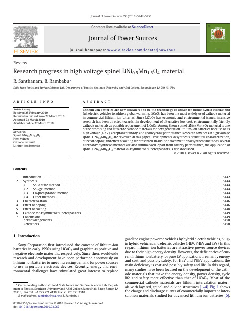
Journal of Power Sources 195 (2010) 5442–5451Contents lists available at ScienceDirectJournal of PowerSourcesj o u r n a l h o m e p a g e :w w w.e l s e v i e r.c o m /l o c a t e /j p o w s o urReviewResearch progress in high voltage spinel LiNi 0.5Mn 1.5O 4materialR.Santhanam,B.Rambabu ∗Solid State Ionics and Surface Sciences Lab,Department of Physics,Southern University and A&M College,Baton Rouge,LA 70813,USAa r t i c l e i n f o Article history:Received 25February 2010Received in revised form 22March 2010Accepted 23March 2010Available online 27 March 2010Keywords:Spinel LiNi 0.5Mn 1.5O 4High voltageCathode material Lithium-ion batteriesa b s t r a c tLithium-ion batteries are now considered to be the technology of choice for future hybrid electric and full electric vehicles to address global warming.LiCoO 2has been the most widely used cathode material in commercial lithium-ion batteries.Since LiCoO 2has economic and environmental issues,intensive research has been directed towards the development of alternative low cost,environmentally friendly cathode materials as possible replacement of LiCoO 2.Among them,spinel LiNi 0.5Mn 1.5O 4material is one of the promising and attractive cathode materials for next generation lithium-ion batteries because of its high voltage (4.7V),acceptable stability,and good cycling performance.Research advances in high voltage spinel LiNi 0.5Mn 1.5O 4are reviewed in this paper.Developments in synthesis,structural characterization,effect of doping,and effect of coating are presented.In addition to conventional synthesis methods,several alternative synthesis methods are also summarized.Apart from battery performance,the application of spinel LiNi 0.5Mn 1.5O 4material in asymmetric supercapacitors is also discussed.© 2010 Elsevier B.V. All rights reserved.Contents 1.Introduction..........................................................................................................................................54422.Synthesis .............................................................................................................................................54442.1.Solid state method............................................................................................................................54442.2.Sol–gel method...............................................................................................................................54442.3.Co-precipitation method.....................................................................................................................54442.4.Other methods................................................................................................................................54443.Characterization......................................................................................................................................54464.Effect of doping ......................................................................................................................................54465.Effect of coating......................................................................................................................................54486.Cathode for asymmetric supercapacitors............................................................................................................54497.Conclusions ..........................................................................................................................................5449Acknowledgements..................................................................................................................................5450References . (5450)1.IntroductionSony Corporation first introduced the concept of lithium-ion batteries in early 1990s using LiCoO 2and graphite as positive and negative electrode materials,respectively.Since then,worldwide research and development have been performed enormously on lithium-ion batteries to meet increasing demand for power sources to use in portable electronic devices.Recently,energy and envi-ronmental challenges have stimulated great interest to replace∗Corresponding author at:Solid State Ionics and Surface Sciences Lab,Depart-ment of Physics,Southern University and A&M College,James Hall,Baton Rouge,LA 70813,USA.Tel.:+12257714130;fax:+12257712310.E-mail address:rambabu@ (B.Rambabu).gasoline engine powered vehicles by hybrid electric vehicles,plug-in hybrid vehicles and electric vehicles (HEV,PHEV and EVs).In this regard,lithium-ion batteries are attractive power source devices due to their high energy density.However,the deficiencies of cur-rent lithium-ion battery for pure EV applications are mainly energy and cost,and possibly safety.For HEV and PHEV applications,the main deficiency is cost and possibly safety and life.In this regard,many studies have been focused on the development of the cath-ode materials that make the energy density,power density,cycle life and safety more effective than that of LiCoO 2.Most of the commercial cathode materials are lithium intercalation materi-als with layered,spinel and olivine structures [1–4].Fig.1shows the charge and discharge curves of commercially important inter-calation materials studied for advanced lithium-ion batteries [5].0378-7753/$–see front matter © 2010 Elsevier B.V. All rights reserved.doi:10.1016/j.jpowsour.2010.03.067R.Santhanam,B.Rambabu/Journal of Power Sources195 (2010) 5442–54515443Fig.1.Charge and discharge curves of(a)Li[Ni0.5Mn1.5]O4,(b)LiMn2O4-based mate-rial of lithium aluminum manganese oxide(LAMO),(c)LiCo1/3Ni1/3Mn1/3O2,(d) LiFePO4,and(e)Li[Li1/3Ti5/3]O4in nonaqueous lithium cells[5].Among the numerous transition metal oxides,manganese-based oxides are particularly attractive as cathode materials because of their low cost and non-toxicity.Among them,LiMn2O4spinel and its derivatives have been extensively studied as promising cathode materials due to their easy preparation,abundance,low cost,and non-toxicity[6–12].Pure LiMn2O4has face-centered spinel struc-ture with Fd3m space group in which the Mn,Li and O ions are in the 16d octahedral sites,8a tetrahedral sites and32e sites,respectively. The isotropic structure of spinel LiMn2O4provides a3D network for lithium-ion diffusion,and hence,this material is suitable for fast lithium insertion and deinsertion reactions[12–18].However,it suffers from poor cycling behavior at elevated temperature[19,20]. In order to overcome this problem,many research groups have been focused on substitution of other transition metals for Mn to make LiM x Mn2−x O4(M=Co,Cr,Ni,Fe,Cu,etc.)[21–25].Sigala et al.suggested that much of the reduced capacity of Cr-doped spinel appears in4.9V plateau and the size of the plateau increases with Cr content[21].Zhong et al.reported that all the metal doped spinels should be reinvestigated for the intercala-tion behavior in the high voltage region[26].During the course of investigations,it has been found that a Ni-doped spinel oxide, LiNi0.5Mn1.5O4is the most promising and attractive one because of its good cycling behavior and relatively high capacity with one dominant plateau at around4.7V whereas other materials exhib-ited two plateaus at around4.0and5.0V[26–28].Great attention has been given to spinel LiNi0.5Mn1.5O4because it provides access to redox couple(Ni III/Ni IV)below4.8V vs.Li.Since these redox cou-ples are pinned at the top of the O–2p bands,a step between them is not observed in the spinel LiNi0.5Mn1.5O4[29].LiNi0.5Mn1.5O4 spinel is fundamentally different from pure spinels as all redox activity takes place on Ni and Mn remains in4+state.This spinel has two different crystal structures of the space groups of Fd3m(non-stoichiometric disordered LiNi0.5Mn1.5O4−ı)in which Mn ions are present in mainly Mn4+and little Mn3+,and P4332(stoichiomet-ric ordered LiNi0.5Mn1.5O4)in which Mn ions are only present in Mn4+.The non-stoichiometric LiNi0.5Mn1.5O4−ıhas face-centered cubic spinel structure with Fd3m space group in which,like pure spinel LiMn2O4,the Ni and Mn,Li and O atoms are occupied in the16d octahedral sites,8a tetrahedral sites and32e sites,respec-tively.In this case,Ni and Mn atoms are randomly distributed in the16d sites.However,the stoichiometric LiNi0.5Mn1.5O4has primitive simple cubic structure with P4332space group in which the Ni,Mn,and Li atoms are occupied in the4a,12d,and4c Fig.2.The spinel structure of LiNi0.5Mn1.5O4(Fd3m)showing diffusion path of lithium[31].sites and O ions are occupied in the8c and24e sites[30].In this case,Ni and Mn atoms are ordered regularly.The disordered LiNi0.5Mn1.5O4−ıspinel was found to have better electrochemical performance than ordered spinel LiNi0.5Mn1.5O4[30].Ceder and co-workers presented the diffusion path of lithium in the disordered LiNi0.5Mn1.5O4−ıspinel as shown in Fig.2[31].The theoretical capacity of LiNi0.5Mn1.5O4is calculated to be147mA h g−1when all lithium-ions can be extracted from this material.The main issues with this spinel material are as follows:(i)the redox couple (Ni III/Ni IV)is at the potential of decomposition of the conventional battery electrolyte(1.0M LiPF6in ethylene carbonate/diethyl car-bonate)and(ii)it is difficult to prepare of pure spinel LiNi0.5Mn1.5O4 due to the formation of Li x Ni1−x O as a second phase.The decom-position of electrolyte occurs at around4.6and5.1V vs.Li in half cell and full cell at room temperature,respectively.The formation of Li x Ni1−x O deteriorates the electrochemical performance of the spinel LiNi0.5Mn1.5O4material[26].Recently,excellent reviews have been published on materials for lithium-ion batteries[4,32–34].Chen and Cheng reported the combination of light weight elements and nanostructured mate-rials for developing advanced lithium-ion batteries[32].Fergus reviewed recent developments of cathode materials for lithium batteries and compared the performance of promising cathode materials and approaches for improving their performances[4]. Kim and Cho reviewed recent research advances on reversible and high capacity nanostructured electrode materials for lithium-ion batteries[33].Synthesis procedures of LiFePO4powders,along with doped and coated derivatives,have been systematically reviewed by Jugovic and Uskokovic[34].In the case of spinel materials, Amatucci and Tarascon reported the optimization of LiMn2O4in their review[35]and Yi et al.[36]reviewed recent developments in the surface modifications of LiMn2O4for lithium-ion batteries. Very recently,Nazar and co-workers published an excellent review on positive electrode materials for lithium-ion and lithium batter-ies[37].They overviewed the developments of positive electrode materials in the past decade and highlighted the ultrahigh capac-ity systems such as Li–S and Li–air batteries for the future.Here, we tried to make a review specifically on spinel LiNi0.5Mn1.5O4 cathode material since this material has the highest voltage(4.7V) among all other layered cathode materials for lithium battery appli-cations.This article provides an overview of selected developments on spinel LiNi0.5Mn1.5O4on synthesis,characterization,effect of doping and effect of coating on the battery performance and the application in asymmetric supercapacitors for the past decade.5444R.Santhanam,B.Rambabu/Journal of Power Sources195 (2010) 5442–54512.Synthesis2.1.Solid state methodThis is the most common method in which stoichiometric mix-ture of starting materials is ground or ball-milled together and the resultant mixture is heat-treated in a furnace.In the case of spinel LiNi0.5Mn1.5O4,appropriate amounts of starting materials, NiCl2·x H2O and MnCl2·x H2O,are thoroughly mixed in the ratio of 1:3.Subsequently,20%excess(NH4)2C2O4·H2O is added to the mix-ture and then the mixture is ground to ensure complete reaction. After drying,the mixture is calcined at400◦C to form the precur-sor containing Ni–Mn.Stoichiometric amount of Li2Co3is added and mixed thoroughly.Then the mixture containing Ni–Mn–Li is calcined at different temperatures ranging from700to900◦C[38]. The purity of the material depends on the starting materials,cal-cination temperature and time.The effect of various Ni precursors on the electrochemical performance has been investigated and the results show that the best electrochemical performance is obtained from Ni(NO3)2·6H2O precursor[39].An improved solid state reac-tion is reported using Li2Co3,NiO and electrolytic MnO2[40].The morphology of the spinel LiNi0.5Mn1.5O4material prepared by solid state method is shown in Fig.3a[40].However,this method has some disadvantages such as inhomogeneity,uncontrollable parti-cle growth and agglomeration.2.2.Sol–gel methodThe sol–gel method can overcome some disadvantages of conventional solid state method because of its low processing tem-perature,high chemical homogeneity,possibility of controlling size and morphology of the particles.Sol–gel method is used to pre-pare spinel LiNi0.5Mn1.5O4by various research groups[41–45].To prepare LiNi0.5Mn1.5O4stoichiometric amounts of lithium acetate [Li(CH3COO)·2H2O],manganese acetate[Mn(CH3COO)2·4H2O], and nickel acetate[Ni(CH3COO)2·4H2O],are dissolved in an appro-priate quantity of distilled water at room temperature.The solution is stirred at50◦C and the citric acid is added to the solution which acts as chelating agent in the polymeric matrix.The pH of the solution is adjusted to7.0by slowly dropping ammonium hydrox-ide drop wise and continued stirring for4h.The temperature of the solution is raised to80–90◦C and continued stirring till the solution turned into high-viscous gel.The resulted gel is dried at 80◦C for24h in a temperature controlled oven of an accuracy of±1◦C.The LiNi0.5Mn1.5O4precursor powder is ground tofine powder and calcined at450◦C under oxygenflowing conditions with a constant heating followed by cooling rate at4◦C min−1to decompose organic constituents.The calcined powder is ground to afine powder and re-sintered at different temperatures and time under oxygenflowing conditions.The morphology of the spinel LiNi0.5Mn1.5O4powder obtained from sol–gel method is presented in Fig.3b[41].2.3.Co-precipitation methodCo-precipitation procedure can easily be handled and the precipitates are generated simultaneously and uniformly dis-persed throughout the solution.To synthesize LiNi0.5Mn1.5O4 powders,the precursor(Ni0.5Mn1.5)(OH)2isfirstly prepared by dissolving stoichiometric amounts of Ni(CH3COO)2·4H2O, and Mn(CH3COO)2·4H2O in distilled water(cationic ratio of Ni:Mn=1:3).The aqueous solution is then precipitated by adding NaOH/NH4OH solution along with continued stirring to obtain mixed hydroxide precipitate.Afterfiltering,washing and drying in a vacuum oven at50–60◦C overnight,the obtained precursor is mixed with required amount of LiOH and calcined at varioustem-Fig.3.SEM images of the spinel LiNi0.5Mn1.5O4synthesized by(a)solid state,(b) sol–gel,and(c)co-precipitation methods[40,41,46].peratures to get LiNi0.5Mn1.5O4powders.This powder is prepared by co-precipitation using different precursors such as metal sulfate, metal carbonate,and metal chlorides[46–48].A representative image of the LiNi0.5Mn1.5O4material prepared by co-precipitation is shown in Fig.3c[46].2.4.Other methodsHigh rate capability was achieved by the nano-rod like LiNi0.5Mn1.5O4spinel powder prepared by polymer assisted(PA) synthesis in which polyethylene glycol(PEG400)was used as sac-rificial template[49].Homogeneous mixing of starting materials at the atomic scale was achieved by radiated polymer gel(RPG) method in which the solution containing starting materials and acrylic acid to synthesize LiNi0.5Mn1.5O4spinel.The solution is polymerized under the condition of Co60␥-ray irradiation(inten-sity55–75Gy min−1)[50].50nm sized LiNi0.5Mn1.5O4having the Fd3m cubic spinel structure is readily prepared by the emulsion drying(ED)method which can intermix cations(Li,Mn and Ni)onR.Santhanam,B.Rambabu/Journal of Power Sources195 (2010) 5442–54515445Fig.4.TEM images of the spinel LiNi0.5Mn1.5O4synthesized by(a)polymer assisted, (b)radiated polymer gel,and(c)emulsion drying methods[49–51].the atomic scale[51].The TEM images of LiNi0.5Mn1.5O4material prepared by PA,RPG and ED methods are shown in Fig.4a–c,respec-tively[49–51].Oh et al.employed mechanochemical process,to synthesize LiNi0.5Mn1.5O4material,in which planetary-type ball mill was adopted for the mechanical activation of the starting materials[52].This method is a common method which uses high energy ball milling to prepare highly homogeneous powders of different species by mechanical activation.The frictional energy formed by the balls and powders and rotation of the bowl would initiate some reactions between the raw materials[53,54].The morphology of the material prepared by mechanochemical method is shown in Fig.5a[52].Fang et al.reported a combinational anneal-ing method to prepare the spinel LiNi0.5Mn1.5O4material[55]. Since high temperature calcination results in oxygen loss,Nidefi-Fig.5.SEM images of the spinel LiNi0.5Mn1.5O4synthesized by(a)mechanochemi-cal,(b)and(c)molten salt,and(d)carbon combustion methods[52,61,62,65].5446R.Santhanam,B.Rambabu/Journal of Power Sources195 (2010) 5442–5451ciency and formation of impurity phases,the cycling performance of the material would be deteriorated.Oxygen loss can be recov-ered by low rate cooling or low temperature annealing[56,57]. Therefore,in the combinational annealing method,the mixed pre-cursors were heated to high temperature and then quickly cooled down to low temperature for isothermal annealing treatment.In this way,LiNi0.5Mn1.5O4material can be prepared with minimum oxygen loss,reduced impurity to obtain good electrochemical per-formance.The main disadvantages of wet methods are high cost and com-plicated synthetic procedure.Molten salt(MS)method is a simple technique to prepare complex oxide materials.This method is based on the use of a salt with low melting point such as alkali metal sulfates,hydroxides,carbonates and chlorides.Highly pure mate-rials can be prepared at relatively low temperatures in MS method due to relatively higher diffusion rates between reaction compo-nents.Various lithium salts are used to prepare lithium manganese oxides and lithium cobalt oxide using MS method[58–60].Spher-ical and well-ordered highly crystalline LiNi0.5Mn1.5O4materials are prepared by MS method by different research groups[61,62]. The SEM images of highly crystalline and spherical LiNi0.5Mn1.5O4 materials prepared by MS method are shown in Fig.5b and c[61,62]. Combustion reaction method is also used for the preparation of various oxide materials[63,64].Zhang et ed carbon combus-tion method(CCS)to prepare cubic LiNi0.5Mn1.5O4material with a space group of Fd3m using carbon as fuel[65].In this CCS method, the structure and particle size could be adjusted by the amount of carbon used for combustion.A representative SEM image of the LiNi0.5Mn1.5O4material prepared by CCS method is shown in Fig.5d [65].3.CharacterizationIt is known that the synthesis of pure phase of LiNi0.5Mn1.5O4 is somewhat difficult due to the presence of unwanted impurities such as NiO and Li x Ni y O.As mentioned earlier,Sun and co-workers successfully synthesized the ordered and disordered spinels by molten salt method[30].To prepare the disordered spinel,the pre-cursors were mixed and calcined at900◦C for3h in a covered alumina crucible.The disordered spinel powders thus obtained were oxidized to ordered spinel by heating at700◦C for48h in air.The ordered(LiNi0.5Mn1.5O4)and disordered(LiNi0.5Mn1.5O4−ı) forms of the spinel material could be differentiated by X-ray diffrac-tion(XRD)measurements.Rietveld analysis was performed on the XRD patterns to identify the ordered and disordered structures of the spinel material.Rietveld refinement profiles are shown in Fig.6 [30].Small peaks representing superstructure were observed for ordered spinel but these peaks were absent in the case of disor-dered spinel.Similar results were also observed for other spinels such as LiMg0.5Mn1.5O4and LiZn0.5Ti1.5O4[66,67].Recently,Shaju and Bruce synthesized nanosized ordered and disordered forms of the spinel using resorcinol–formaldehyde route[68].These authors used lattice parameters obtained from XRD analysis to differen-tiate the two forms of the spinel material.In the ordered spinel, the oxidation states of Ni and Mn are+2and+4,respectively, whereas a small amount of oxygen loss in the disordered spinel is compensated by the formation of Mn3+.Since the size of Mn3+is bigger than Mn2+,the cubic lattice parameter is larger in disordered (8.1733Å)than that of ordered spinel(8.1677Å).Interestingly, transmission electron microscopy(TEM)was used to observe the structural differences between ordered LiNi0.5Mn1.5O4and disor-dered LiNi0.5Mn1.5O4−ıspinels and the results are shown in Fig.7[30].The disordered spinel showed electron diffraction pattern ofa typical spinel and however,the ordered spinel showed extra diffraction spots(superlattice pattern)in addition to the spots observed for purespinel.Fig.6.Rietveld refinement profiles of XRD data for(a)LiNi0.5Mn1.5O4−ı,and(b) LiNi0.5Mn1.5O4powders[30].Cyclic voltammetry is an excellent electrochemical technique to study the redox reactions and it has been widely used by electrochemists in various researchfields.This technique was con-veniently used to characterize the spinel LiNi0.5Mn1.5O4material by different research groups[31,41,46].A typical cyclic voltam-mogram of disordered spinel LiNi0.5Mn1.5O4−ıis shown in Fig.8 [31].Three well-defined reversible peaks were observed during charge and discharge.The appearance of4V peak was due to Mn3+ ions which were formed by the oxygen loss during high tem-perature calcinations.The two major peaks appearing between 4.5and5V during charge and discharge cycling were due to the redox couples Ni2+/Ni3+and Ni3+/Ni4+or ordering of lithium and vacancies at x=0.5[69,70].For ordered spinel,the4V peaks were absent because oxidation states of Ni and Mn were+2and+4, respectively[30].Charge and discharge measurements were used to characterize and differentiate ordered and disordered spinel LiNi0.5Mn1.5O4−ımaterials.Thefirst two cycles of charge and dis-charge voltage profiles of two different spinels are shown in Fig.9 [68].The difference in charge capacity betweenfirst and second cycle was due to electrolyte oxidation[71,72].The voltage step appearing around4.7V was more clear in the case of disordered spinel[71–73].This difference in the voltage plateau could be used to identify if the spinel material was ordered or disordered.A small step appearing around4V in the disordered material was associ-ated with the Mn3+/4+redox couple[71–73].4.Effect of dopingMany different elements can be doped into the high voltage LiNi0.5Mn1.5O4spinel structure,and they impact the structure,its stability on lithium insertion/deinsertion,and the capacity reten-tion on cycling.The use of high voltage material may have adverse effects such as possible electrolyte decomposition which may increase capacity fading on cycling.To improve the high volt-age electrochemical performance of LiNi0.5Mn1.5O4spinel,variousR.Santhanam,B.Rambabu /Journal of Power Sources 195 (2010) 5442–54515447Fig.7.Electron diffraction patterns of (a)LiNi 0.5Mn 1.5O 4−ıand (b)LiNi 0.5Mn 1.5O 4phases in the [99]zone [30].Fig.8.Cyclic voltammogram of LiNi 0.5Mn 1.5O 4electrode cycled between 3.5and 5V vs.Li/Li +at 0.2mV s −1scan rate [30].Fig.9.Charge and discharge voltage profiles for the first and second cycles at 30◦C and 75mA h g −1between 3.5and 5.0V for (a)the disordered phase and (b)the ordered phase [68].dopants have been proposed by different research groups.Titanium (Ti)was added as a dopant in the LiNi 0.5Mn 1.5O 4spinel structure [74,75].Ti doping improved the disordering of the transition met-als and consequently lowers the symmetry from primitive simple cubic structure (P 4332)to face-centered spinel (Fd 3m ).In addition,the Ti doped LiNi 0.5Mn 1.5−x Ti x O 4spinel exhibited higher operat-ing voltage,faster lithium diffusion and better rate capability than undoped spinel.However,the capacity was decreased on doping of larger amount of Ti due to blocking of migration pathway of electrons in octahedral sites.Voltage profiles of LiNi 0.5Mn 1.5−x Ti x O 4spinel with various amounts of Ti doping are shown in Fig.10[74].Alcantara et al.also reported that the doping of small amounts of Ti improved the electrochemical performance whereas a deterio-ration of the reversible capacity was observed for large amounts of Ti [75].Iron (Fe)was used as a dopant for LiNi 0.5Mn 1.5O 4spinel and it was shown to improve the electrochemical perfor-mance [76,77].The presence of Fe in the tetrahedral sites of the structure stabilizes the solid during extended cycling.The electro-chemical performance of LiNi 0.5Mn 1.5O 4spinel was also studied by double substitution with Ti and Fe [78].The material containing 0.05Fe +0.05Ti showed a two phase mechanism of lithium extrac-tion and in contrast,the material containing 0.10Fe +0.10Ti showed only one phase.It was suggested that the best capacity retention could be achieved by using the LiFe 0.10Ti 0.10Ni 0.45Mn 1.35O 4com-position associated with single phase mechanism combined with structural stabilization by Ti.Chromium (Cr)could be added to the LiNi 0.5Mn 1.5O 4spinel structure as a dopant [79–81].The influence of Cr content on the electrochemical performance of the spinel was studied in detail.It was reported that the particle size depended on Cr content.5448R.Santhanam,B.Rambabu /Journal of Power Sources195 (2010) 5442–5451Fig.10.Voltage profiles of LiNi 0.5Mn 1.5−x Ti x O 4with various amounts (x )of Ti doping:(a)x =0,(b)x =0.05,(c)x =0.1,(d)x =0.2,(e)x =0.3,and (f)x =0.5[74].Moreover,Cr-doped spinel delivered higher discharge capacity and capacity retention than that of undoped spinel.Another element that was used as a dopant for LiNi 0.5Mn 1.5O 4spinel was ruthenium (Ru)[82].The rate capability and cycling performance were sig-nificantly improved by Ru doping.High capacity of the Ru doped spinel was due to minimized polarization and improved electrical conductivity.The enhanced rate capability and cyclability resulted from improved structural stability of LiNi 0.5Mn 1.5O 4spinel by Ru.Zirconium (Zr)and aluminum (Al)also have similar effects like other dopants.From Raman spectra,Oh et al.found that the struc-ture of the Al and Zr doped materials was ordered spinel and Cr doped spinel was disordered.They believed that the excellent elec-trochemical properties of the Cr-doped spinel might be due to high electrical conductivity,chemical and structural stability [83].Magnesium (Mg)doping was shown to improve the performances of LiNi 0.5Mn 1.5O 4spinel [84].LiMg 0.07Ni 0.43Mn 1.5O 4material was prepared by solid state,sol–gel and xerogel methods and the elec-trochemical performances were compared.It was found that the spinel materials prepared by sol–gel and xerogel methods were better than solid state method.This was due to sub-micron sized particles of single crystals together with nanoparticles obtained from sol–gel and xerogel methods.Another dopant that could be occupied in the anion site is fluorine which was a common dopant in the field of lithium-ion bat-teries.The reversible capacity of high voltage LiNi 0.5Mn 1.5O 4spinel material was improved by fluorine doping (LiNi 0.5Mn 1.5O 3.975F 0.05)[85].It was reported that the performance improvement was mainly because of suppression of the formation of NiO impu-rity during synthesis.Fluorine doping in the oxygen sites of the spinel could change the lattice parameters and bonding energy as reported by Du et al.[86].They prepared the spinel material with different fluoring contents.For the materials with fluorine beyond 0.1instead of oxygen,the capacity decreased but the cyclabilitywas significantly improved.This result was due to fine-structure arising from fluorine doping.5.Effect of coatingIt should be noted that lithium transition metal oxides can react with the electrolyte and lead to safety issues.Significant efforts have made by different research groups to increase the sta-bility of lithium metal oxides.It was shown that better stability can be achieved by coating the materials with stabilizing surface layer.Lithium metal oxides were coated with various oxides and phosphates and demonstrated improved capacity retention dur-ing cycling.Surface modifications of LiNi 0.5Mn 1.5O 4spinel material by coating various oxides and phosphates such as ZnO [87–90],SnO 2[91],Li 3PO 4[92],and different metal treatments such as Zn [93],Au [94],Ag [95]have been widely investigated.In the case of ZnO-coated LiNi 0.5Mn 1.5O 4,the ZnO-coated electrode delivered the capacity of 137mA h g −1without any capacity loss even after 50cycles at 55◦C as shown in Fig.11[88].LiNi 0.5Mn 1.5O 4sur-face was protected by ZnO coating,suppressed Mn dissolution and increased the structural stability.ZnO played an important role in reducing the HF content in the electrolyte.The ZnO coating layer was acted like a scavenger of fluoride anions from HF gen-erated from the decomposition of LiPF 6salt in the electrolyte by transforming HF to ZnF 2[87–90].Similarly,SnO 2coating on the surface of the LiNi 0.5Mn 1.5O 4improved capacity retention and the improvement enhanced with increased SnO 2content.Based on the X-ray photoelectron spectroscopy results,Fan et al.showed that the main reason for the electrochemical stability was due to rela-tively low content of LiF in the SnO 2coated LiNi 0.5Mn 1.5O 4[91].In a similar manner,Li 3PO 4coating protects the surface of the LiNi 0.5Mn 1.5O 4material and function as a solid electrolyte interface between LiNi 0.5Mn 1.5O 4and solid polymer electrolyte (SPE)to pre-。
铝镁氢氧化钠原电池 电极反应式四羟基合铝酸钠
铝镁氢氧化钠原电池电极反应式四羟基合铝酸钠The topic I will be discussing is the electrode reaction of aluminum-magnesium hydrotalcite-based sodium aluminate (NaAlO2) primary battery.铝镁氢氧化钠原电池采用四羟基合铝酸钠作为电极反应源,这种新型电池具有很高的能量密度和长寿命。
在工作过程中,主要发生两个电极反应:负极反应和正极反应。
The aluminum-magnesium hydrotalcite-based sodium aluminate primary battery, using NaAlO2 as the electrode reactant, exhibits high energy density and long lifespan. During operation, two electrode reactions take place: the negative electrode reaction and the positive electrode reaction.在负极上,铝金属首先被氢离子还原为铝离子,生成水。
这个反应式可以表示为:At the negative electrode, aluminum metal is first reduced by hydrogen ions to form aluminum ions, producing water.This reaction can be represented as:2 Al (s) + 6 H⁺ (aq) → 2 Al³⁺ (aq) +3 H₂O (l)而在正极上,四羟基合铝酸钠溶解生成了氢氧化钠。
这个反应式可以表示为:On the positive electrode side, NaAlO2 dissolves to produce sodium hydroxide. This reaction can be represented as:NaAlO₂ (s) + H₂O (l) → NaOH (aq) + Al(OH)₄⁻ (aq)通过这两个电极反应,铝和四羟基合铝酸钠在电池内部发生氧化还原反应来释放出能量。
基于负极对称电池分析电池容量损失
图1 负极对称电池不同循环周数的充放电曲线,(a)100% SOC-Pristine,(b)100% SOC-0% SOC Fig.1 The charge/discharge curves of anode symmetric cells after different cycles(a)100% SOC-Pristine(b)100% SOC-0% SOC.
SOC-Pristine负 极 对 称 电 池 首 圈 充 电 在 -1 V ~ -0.5V之间有 平 台 出 现,而 100% SOC-0% SOC 负极对称电池在此电压范围内并未出现平台 ,这是由
渡 金 属 溶 出 以 及 正 极 结 构 破 坏 ,而 在 石 墨 负 极 对 称 电 池 中 无 正 极 过 渡 金 属 溶 出 及 结 构 破 坏 ,且 其 电 压 范 围 窄 ,电 解 液 的 氧 化 可 以 忽 略 不 计 ,因 此 ,石 墨 负 极 对 称
Vol.24No.2
81
Apr.2020
电 池工业 彭 文,等:基于负极对称电池分析电池容量损失 Chinese BatteryIndustry
图 2 (a)不 同 循 环 周 数 的 库 伦 效 率 , (b)不 同 循 环 周 数 的 充 放 电 容 量
Fig.2 The coulombic efficiency (panel a)and the charge/discharge capacity (panel b)versus cycle number.
Abstract:Anode symmetric cells were assembled using two identical electrodes,one in a lithium state and another one in a delithiated or pristine state.The charging-discharging regime of graphite symmetric cells were studied.And the electrochemical impedance spectrum of different state of charge (SOC )was also analyzed.A sloping curve from -1Vto 0.5V was only observed during the first charging curve of the 100% SOC-Pristine graphite symmetric cell.The voltage platform was suggested to the formation of SEI layer in the pristine graphite surface.The imped- ance of symmetric cell in 0% SOC and 100% SOC reached the maximum.While the impedance achieved the minimum value in 50% SOC. Keywords:Li-ion battery;Anode symmetric cells;SEI layer;Impedance
- 1、下载文档前请自行甄别文档内容的完整性,平台不提供额外的编辑、内容补充、找答案等附加服务。
- 2、"仅部分预览"的文档,不可在线预览部分如存在完整性等问题,可反馈申请退款(可完整预览的文档不适用该条件!)。
- 3、如文档侵犯您的权益,请联系客服反馈,我们会尽快为您处理(人工客服工作时间:9:00-18:30)。
ElectrochimicaActa54(2009)3211–3217ContentslistsavailableatScienceDirectElectrochimicaActa
journalhomepage:www.elsevier.com/locate/electacta
AdelithiatedLiNi0.65Co0.25Mn0.10O2electrodematerial:Astructural,magneticandelectrochemicalstudy
MohammedDahbia,J.MagnusWikbergb,IsmaelSaadounea,∗,TorbjörnGustafssonc,PeterSvedlindhb,KristinaEdströmc
aECME,FSTMarrakech,UniversityCadiAyyad,BP549,Av.A.Khattabi,Marrakech,Morocco
bDepartmentofEngineeringSciences,UppsalaUniversity,Box534,SE-75121Uppsala,Sweden
cDepartmentofMaterialsChemistry,UppsalaUniversity,Box538,SE-75121Uppsala,Sweden
articleinfoArticlehistory:Received8October2008Receivedinrevisedform17November2008Accepted17November2008Availableonline3December2008Keywords:LithiumbatteriesLayeredcathodeMagnetizationElectrochemicalcyclingLiNi0.65Co0.25Mn0.10O2abstractAcrystallineLiNi0.65Co0.25Mn0.10O2electrodematerialwassynthesizedbythecombustionmethodat900◦Cfor1h.Rietveldrefinementshowslessthan3%ofLi/Nidisorderinthestructure.Lithiumextrac-tioninvolvesonlytheNi2+/Ni4+redoxcouplewhileCo3+andMn4+remainelectrochemicallyinactive.Nostructuraltransitionwasdetectedduringcyclinginthewholecompositionrange0thehexagonalcellvolumechangesbyonly3%whenalllithiumwasremovedindicatingagoodmechani-calstabilityofthestudiedcompound.LiNi0.65Co0.25Mn0.10O2hasadischargecapacityof150mAh/ginthe
voltagerange2.5–4.5V,butthebestelectrochemicalperformancewasobtainedwithanuppercut-offpotentialof4.3V.Magneticmeasurementsrevealcompetingantiferromagneticandferromagneticinter-actions–varyinginstrengthasafunctionoflithiumcontent–yieldingalowtemperaturemagneticallyfrustratedstate.TheevolutionofthemagneticpropertieswithlithiumcontentconfirmsthepreferentialoxidationofNiionscomparedtoCo3+andMn4+duringthedelithiationprocess.
©2008ElsevierLtd.Allrightsreserved.
1.IntroductionThemostwidelyusedcathodematerialsintoday’scommer-cialLi-ionbatteriesarethelayeredlithiumtransitionmetaloxideswhereLiCoO2hassofarbeenthemostwidelyused.Touselargeamountsofcobaltis,however,expensiveandthereisthereforeastrongdrivingforcetofindnewcheaperandenvironmentallybenigncathodematerialsleadingtobatterieswithhigherenergydensities.Oneroutetotakeistoexchangecobaltfornickel.AlthoughLiNiO2hasahigherspecificcapacityandispotentiallycheaperthanLiCoO2,itisbothchemicallyandelectrochemicallyunstable,leadingtobothsynthesisandsafetyproblems[1–3].LiCoO2issuperiorinthisrespectandwas,indeed,thecathodeusedinSony’sveryfirstLi-ionbatteries.ExtractionorinsertionofLi+inLiCoO2takesplacearound4V,whichshouldresultinahighgravimetricenergydensityforfullLiextraction.However,whensuchlargeamountsoflithiumareremoved(athighpotentials),irreversiblestructuralchangesoccur[4,5].InLiCoO2andincobalt-richLiNi1−xCoxO2phases,thisiscausedmainlybyexothermicreactionswiththeelectrolyteleadingtolossofoxygen[6–8].SucheffectsareevenmorepronouncedinthelessthermallystableLiNiO2.Thebestcompromiseisreachedwhen∗Correspondingauthor.Tel.:+21261486464;fax:+21224433170.E-mailaddress:saadoune1@yahoo.fr(I.Saadoune).combiningcobaltandnickelintothenickel-richLiNi1−xCoxO2solidsolution.However,forthiscompoundotherstructuralinstabilitiesariseinthehighlydelithiatedstate,wherenickelionsmigrateintothelithiumsitesinthestructure[9].Thisisthenlimitinglithiumdif-fusionandreducingstoragecapacity.Incommercialapplications,only0.5Liisthereforeremovedfromthestructure,correspondingtoacut-offat4.2Vandatheoreticalcapacityof130mAh/g.Anumberofelectrochemicallyinertsubstituentsfornickelorcobalthavebeentestedwiththeattempttostabilizethestruc-ture,e.g.,Al,Ga,MgandTi.TheLiNi1−y−zCoyAlzO2systemhasbeen
foundtogivethebestperformance,andistodayusedinmanycommercialapplications[10–12].Recently,mixedmetaloxidesofnickel,cobaltandmanganesehaveattractedextensiveatten-tion,suchasLiNi1/3Co1/3Mn1/3O2[13–15]andLiNi1−y−zCoyMnzO2
[16–19]astheymayovercomethedrawbacksofLiNiO2,LiCoO2and
LiMnO2.Thesematerialsexhibitexcellentproperties.Inthecaseof
LiNi1/3Co1/3Mn1/3O2,forexample,highcapacitiesof150mAh/gfora4.2Vcut-offand200mAh/gwhenchargingupto4.6and5.0Vareattainable.Furthermore,acertainamountofnickelinthelithiumlayerseemstostabilizethestructureandimprovecapacityreten-tion.InarecentlypublishedpaperdevotedtotheLixNi0.7Co0.3O
2
system,wehaveshownthestructuralinstabilityforthehighly
delithiatedphaseduringthechargingprocess[20].Inordertocir-cumventthisproblem,thepartialsubstitutionofNiandCobyothercations,typicallyMn,wasinvestigated.Indeed,wehaveshown
0013-4686/$–seefrontmatter©2008ElsevierLtd.Allrightsreserved.doi:10.1016/j.electacta.2008.11.057