EZON说明书
至龙一号200TX-WP产品说明书
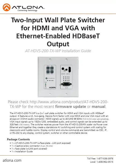
The AT-HDVS-200-TX-WP is a 2×1 wall plate switcher for HDMI and VGA inputs with HDBaseT output. It features a US, two-gang, Decora form factor with one HDMI and one VGA input with an always-on 3.5mm audio connector. HDMI signals up to 4K/UHD @ 60Hz (YUV 4:2:0 color sub-sampling), VGA input signals up to 1920×1200, embedded audio, and control signals can be extended up to 328 feet (100 meters). The switcher receives power from the AT-HDVS-200-RX scaler via Power over Ethernet and together they create a standalone AV switching and control system with scaling for classrooms and huddle rooms. Display control and volume commands are transmitted via CEC, IP, or RS-232 to any display, control system, switcher or other controllable device.• 1 x AT-HDVS-200-TX-WP (w/face plate - LAN port exposed)• 1 x Captive screw connector (3 pin: RS-232)• 1 x Face plate (w/LAN port covered)• 1 x Installation GuidePackage ContentsAT-HDVS-200-TX-WP Installation GuidePlease check /product/AT-HDVS-200-TX-WP for the most recent firmware update or manual .Two-Input Wall Plate Switcher for HDMI and VGA with Ethernet-Enabled HDBaseTOutputPanel Description1. INPUT button: Use to switch between VGA and HDMI sources2. DISPLAY button: Can be programmed to perform different functionsDefault action will turn video output on/off for the switcherSend on/off command to CEC, RS-232, or TCP/IP controllable displays or other connecteddevicesSends RS-232 or TCP/IP trigger command when used with a compatible switcher(e.g. CLSO PoE series)3. PW LED: Will illuminate when receiving powerLINK LED: Illuminates when receiving signal from the receiver4. VOLUME buttons: Adjust output volume of the switcher or connected device when programmedNote: To mute or unmute output audio, press both volume buttons together. LED will turn red when muted5. AUDIO IN port: Connect analog audio here6. HDMI IN port: Connect HDMI source here7. LAN (black)port: Connect network switch or router to this port for Ethernet, TCP/IP, orwebGUI control8. VGA IN port: Connect VGA source here9. RS-232 port: Connect control system to RS-232 port10. HDBaseT(blue)port: Connect to an HDBaseT PoE receivere.g. AT-HDVS-200-RX or UHD-CLSO PoE series switcher/scalersNote: To ensure compatibility, please be certain both transmitter and receiver have blue or blue bordered HDBaseT ports. This ensures both products are PoE (48V) compliant. The HDVS-200-TX is not compatible with PoCC (black RJ45, 24V) devicesConnectingThe captive screw connectors havea contact bar that is adjusted tocompress the wire against the top contact plate. Use the screws at the top of the connector to compress the wire against the contact plate.When connecting the cables to the female captive screw connector it is important that the wires be terminated correctly. The female captive screw connector has a contact plate at the top and must have the wires touching it for signal to pass. When wired correctly (see picture A) the signal will pass, incorrectly (see picture B) no signal will pass.ClockwiseCounter ClockwiseTurn the screws clockwise toraise the contact bar to theupper contact plate and hold the wires in place.Turn the screws counter clockwise to lower the contact bar to release thewires.RS-232 captive screw connector is included. RS-232 pin out will be determined by the RS-232 cable and will connect as Rx (receiver), Tx (transmitter), and(ground). (See picture 1)RS-232Typical pin out:2 - TX - Transmitter3 - RX - Receiver 5 - GND - GroundPin out color will differ per RS-232 cable.1543298761RS-232RS-232RX TX The captive screw connectors allow you to cut cables to a suitable length, reducing cable clutter while providing a more reliable connection.Captive ScrewNote: IP addresses may also be found using common free IP scanner software such as “Advanced IP Scanner”*Atlona does not assume responsibility for damage caused by other programs installed onto a computer, verify programs before installing *webGUIAtlona has created an easy to use webGUI for setup and changes to the configuration of the HDVS-200-TX-WP.To begin, plug a LAN cable into the LAN port of the HDVS-200-TX-WP and the network switch, then type the IP address of the unit into a web browser of a PC connected to the same network (as seen below).Important: If any stability issues are experienced, disable any anti-virus or firewall that may interfere with network communication to the switcher. Once set up is done and the switcher webGUI is no longer being used, the firewall and anti-virus can be re-enabled.A login screen will appear (this is the same log in for admin and general users). For the first log in (and future admin changes) the username is “root” and password is “Atlona”.Only the admin password can be changed (see User Manual). The username will always remain “root”. Note:Connection Diagram (with HDVS-200-RX)HDBaseTAudioDry CCRouterConnection Diagram (with PoE UHD-CLSO series)Troubleshooting1. The Auto-Switch feature isn’t working. How do I enable it?You can enable Auto-switching by using the AutoSW on command via TCP/IP or RS-232, orthrough the WebGU.2. I want to pass only analog audio without video. How do I do this?Place the unit in “standalone” mode. This mode can be enabled using the FreeRun oncommand via TCP/IP or RS-232, or through the webGUI.3. How do I update the firmware?The firmware can be updated using the USB port or through the webGUI.4. How do I find the IP address?Run the IPCFG command using either RS-232 or TCP/IP. You can also get the IP addressthrough the webGUI and AMS.5. How do I switch between DHCP and Static IP modes?For the AT-HDVS-200-TX, DHCP can be turned on/off by pressing the INPUT button for 15seconds. For the AT-HDVS-200-RX, DHCP can be turned on/off by pressing the AUTO button for 15 seconds. You can also toggle between DHCP and Static IP modes using the IPDHCPcommand via TCP/IP or RS-232, or by using the webGUI or AMS.6. What is the default IP address?The default static IP address is 192.168.1.254. Please note that the default static IP for both the wall plate/transmitter (HDVS-200-TX-WP) and the receiver (HDVS-200-RX) are the same.7. I can’t control my display. What’s wrong?First, check that the desired control method is selected (TCP/IP, RS-232, or CEC). If you areusing RS-232, make sure that the baud rate for RXZone 1 (found under the webGUI)matches your display settings. The baud rate can be set through the webGUI or by using the RxRSparaZ1 command via TCP/IP or RS-232. When using the RxRSparaZ1 command, use the following syntax: RxRSparaZ1[baudrate,data-bits,parity,stop-bits].Example: RxRSparaZ1[115200,8,0,1]。
爱达顿EZ智能电源系列产品介绍说明书
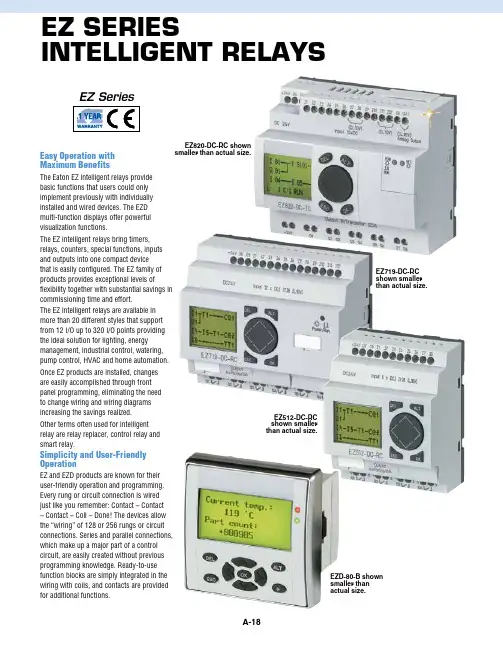
EZ SEriESintElligEnt rElaySEZ SeriesEZ820-DC-RC shown smaller than actual size.EZ719-DC-RC shown smaller than actual size.EZ512-DC-RC shown smaller than actual size.Easy Operation with Maximum BenefitsThe Eaton EZ intelligent relays provide basic functions that users could only implement previously with individually installed and wired devices. The EZD multi-function displays offer powerful visualization functions.The EZ intelligent relays bring timers, relays, counters, special functions, inputs and outputs into one compact device that is easily configured. The EZ family of products provides exceptional levels offlexibility together with substantial savings in commissioning time and effort.The EZ intelligent relays are available in more than 20 different styles that support from 12 I/O up to 320 I/O points providing the ideal solution for lighting, energy management, industrial control, watering, pump control, HVAC and home automation. Once EZ products are installed, changes are easily accomplished through front panel programming, eliminating the need to change wiring and wiring diagrams increasing the savings realized. Other terms often used for intelligent relay are relay replacer, control relay and smart relay.Simplicity and User-Friendly OperationEZ and EZD products are known for their user-friendly operation and programming. Every rung or circuit connection is wired just like you remember: Contact – Contact – Contact – Coil – Done! The devices allow the “wiring” of 128 or 256 rungs or circuit connections. Series and parallel connections, which make up a major part of a control circuit, are easily created without previous programming knowledge. Ready-to-use function blocks are simply integrated in the wiring with coils, and contacts are provided for additional functions.EZD-80-B shown smaller than actual size.EZ500 SeriesEZ500 Series— for controllingsmall applications with up to 12 input/output signals. Models are available with and without displays.DIN rail mounted.EZ512-AC-RC shown smaller than actual size.EZ512-DC-RC shown smaller than actual size.Ordering Example: EZ512-AC-RCX, 12 I/O, clock, no display.Everything Needed is Built-InDepending on the device selected, EZ and EZD products provide users with timing relays, flash relays, counters, comparators, timer switches and other ready-to-use functions. The circuit diagram display of serial and parallel connections, unlikethe display of AND and OR operations in a function block diagram, offers a more manageable display of the circuit. Every EZ and EZD intelligent relay features an integrated power flow display to ensure safe operation during commissioning and helps identify errors in the circuit diagram. For ease-of-use, energized rungs are highlighted, and non-energized rungs are dimmed.Security Means SafetyThe finished circuit diagram is storedinternally and can also be saved externally on a memory module (EEPROM) for transport, security and backup. Multi-level password protection secures your circuit diagram from unauthorized viewing, editing, copying or deleting.l 8 Digital Inputs l 4 Digital Inputs l 128 Rungs of 3 Contacts and 1 Coil Each l 16 Operating and Message Texts l 2 Analog Inputs (10-Bit) Optional (Not with 240 Vac)l 2 High-Speed Inputs, 1 kHz (Only DC Devices)l 12 Digital Inputsl 6 Digital Relay Outputs l 256 Rungs of 4 Contacts and 1 Coil Each l 32 Operating and Message Texts l 4 Analog Inputs (10-Bit)Optional (Not with 230 Vac)l 4 High-Speed Inputs,3/5 kHz (Only DC Devices)l 1 Digital Expansion orNetwork Connectionl N etworkable via EZ-NETwith Up to 8 Stations l 1 Analog Output (10 bit)EZ819-AC-RC shown smallerthan actual size.EZ700 Series— for controlling medium-sized applications with up to 40 input/output signals. DIN rail mounted.EZ719-DC-RC shown smaller than actual size.EZ719-AC-RCXshown smaller than actual size.EZ700 Series EZ800 Seriesl 12 Digital Inputs l 6 Digital Relay Outputs l 128 Rungs of 3 Contacts and 1 Coil Each l 16 Operating and Message Texts l 4 Analog Inputs (10-Bit) Optional (Not with 230 Vac)l 2 High-Speed Inputs, 1 kHz (Only DC Devices)l 1 Digital Expansion or Network ConnectionEZ800 Series— for controlling large scaleapplications with up to 320 input/ outputsignals. Models are available withand without displays. DIN rail mounted.EZD80-B shown smaller than actual size.EZD-R16 shown smaller than actual size.EZD Assembly. Display + Cpu + I/O Module.shown smaller than actual size.EZD-Cp8-nt shown smaller than actual size.EZD Modular RelaysThe EZD modular intelligent relays allows you to assemble a system to meet your exact requirements. A system consists of the following components:1. EZD display with or without buttons2. C PU with or without clock; in a varietyof power configurations 3. I/O modulel 12 Digital Inputs l 4 Digital Relay Outputs l 256 Rungs of 4 Contacts and 1 Coil Each l 24 KB Mask Memory on a Fully Graphical, Backlit Display (64 x 132 Pixels) l 4 Analog Inputs (10-Bit) Optional (Not with 230 Vac)l 4 High-Speed Inputs, 3/5 kHz (Only DC Devices)l 1 Digital Expansion or Network Connection l N etworkable via EZ-NET with Up to 8 Stations l 1 Analog Output (10-Bit)ExpanSion ModulESOrdering Example: EZ618-AC-RE, 18 I/O expansion.EZ618-DC-RE shownconected to EZ820-DC-RC (see page A-20), shown smaller than actual size.Expansion modules are available forincreasing the input/output of the EZ700/800 and EZD intelligent relays to 24 inputs and up to 16 outputs. Expansion modules can be mounted directly to the EZ/EZD unit.EZSoft User-Friendly Circuit Diagram EditorEZSoft makes things particularly easy for users. The graphical editor shows the circuit diagram immediately in the display format required. Selection menus and drag & drop functions simplify circuit diagram creation. Simply select contacts and coils and connect with the mouse – that’s it! In addition to the editing functions, EZSoft is available for straightforward circuit diagram input. All software includes user-friendly menus and Help screens. EZSoft offers the following display formats for viewing,editing and printing out your program:l I EC format, with contact and coilsymbols using international standards l E Z circuit diagram, same as what is seen when programming from theEZ front panell A NSI format, in compliance withAmerican standardsEZ is Maintenance-FreeThe finished program is stored in EZ’snon-volatile memory until modified.Additional auxiliary power or batteries are notrequired. The intelligent relays are entirelymaintenance-free. Circuit diagrams andparameters are saved in the event of a powerfailure. If a power failure occurs, the EZcontroller stores switch positions and valuessuch as operating hours, meters, countersand timing relays. When power is restoredthe values are restored. This retentivefeature for the different function blocks anddata is available on all EZ intelligent relaymodels.EZSoft supports users who are configuring,programming and defining parametersfor EZ intelligent relays and creatingvisualization functions for EZD displays.When intelligent relays are connected toEZ-NET, all connected devices can beaccessed and their programs loaded froma single intelligent relay. The integratedoffline simulation tool allows users to testthe functionality of the circuit diagrambefore commissioning, without the needfor a connected device. The commentfunction for contacts, coils and functionblocks helps provide a clear overview ofthe circuit diagram. A cover sheet with acustomized company logo and different textfields, as well as the cross-reference list withcomments, can turn printouts into the perfectdocumentation for applications.。
老式三星ezon-7001电子锁说明书
老式三星ezon-7001电子锁说明书
一、按健说明
井号健:进入或确认;x号健:返回或退出:9号健:上:0号健:
二、用户权限说
进入管理菜单,添加、删除用户,修改密码、查询记录等功能,任何条件下可开门。
普能用户:
正常情况下可开门。
来宾用户限制条件卜可开门。
具有门禁限制功能。
三、基本功能操作
1、首次使用使用模式井一设置时问井输入管理员ID(比如001)井输入指纹3次(手指开门正常方式放置)输入密码(3到18位)(比如12345)井(2遍)(有遥控器常按遥控开门3秒)。
x退出,设置成功。
开锁时输入密码:00112345可以开锁。
2、添加用户井进入菜单选择注册用户井,验证管理员(可输入管理员指纹或管理员密码)选择注册普通用户,输入ID号(011到040任意3位)井,输入指纹(3次)输入密码3到18位)井(2遍)设置成功。
x退出或关闭系统。
3、删除用户井进入菜单(11)选择删除用户井一验证管理员(可输入管理员指纹或管理员密码井)选择删除普通用户被删除的
ID号井一删除成功,x退出或关闭系统。
老式三星ezon电子锁说明书
老式三星ezon电子锁说明书
说明书如下:
1、特点:本工程各户的入户门锁,采用的是三星电子门锁,具有以下功能:卡开启功能、密码开启功能、自动上锁功能、睡眠锁闭功能、声音提示功能、火灾报警功能。
、组成:室外部分、室内部分、感应卡钥匙、锁芯、锁销挡片、说明书、应急钥匙、AA电池。
??、初始化方法(管理密码、密码、卡、钥匙)
删除所有(管理密码密码卡钥匙)注册信息
方法1:同时按卡注册按钮和遥控器注册按钮5秒→滑盖自动上移后输入初始管理密码→按“*”结束
方法2:同时按卡注册按钮和遥控器注册按H5秒→滑盖白动上移后输入“4560852580”一按“*”结束
??、管理密码注册方法
同时按住open键和密码注册键→滑盖自动上移后输入要注册新管理密码→“*”一再输一次→“*”结束
注意事项:在输入过程中,工作指示灯因输入错误而闪烁并发出“滴沥滴沥“的报警音时应从头开始重新输入。
出厂的管理密码设为“1234”,管理密码只能更改,不能删除。
Magento 2用户指南:登录作客户说明书
Login As Customerfor Magento 2User GuideVersion 1.0Table of ContentsI) Introduction (2)II) Where to Find Extension (3)III) Log In From Customer Grid Page (4)IV) Log In From Customer View Page (5)V) Log In From Order Grid Page (6)VI) Log In From Order View Page (7)VII) Login Logs (8)VIII) Limit Login Permission to Specific Sub-Admin Users (11)IX) Support (14)I) IntroductionLogin As Customer for Magento 2g ives admins the ability to log in to customer accounts from the backend in one click without the necessity to request username and password from customers. Therefore, the admins can resolve any issue related to customer accounts or purchasing process quickly and efficiently.●Log in to customer accounts in one click●Track and record all login actions●Limit login permission to specific sub-admin usersII) Where to Find ExtensionAfter installing the extension, navigate to S tores > Settings > Configuration:In the left panel, span M agezon Extensions and click L ogin As Customer. In the General section on the right-hand side, you can choose Yes/No from E nable drop-down to enable/disable the extension:III) Log In From Customer Grid Page- Go to C ustomers > All Customers and you’ll see a grid containing all customers of your website:- In A ction column, click S elect drop-down list and click L ogin As Customer to log in to the account of your chosen customer:IV) Log In From Customer View Page- When you open a customer view page, click L ogin As Customer on the top bar to log in to the customer account:V) Log In From Order Grid Page- Go to S ales > Operations > Orders and you’ll see a grid containing all orders:- In A ction column, click S elect drop-down list and click L ogin As Customer to log in to the account of the customer with this order:VI) Log In From Order View Page- When you open an order view page, click L ogin As Customer on the top bar to log into the customer account:VII) Login Logs- Login As Customer extension allows recording any access to any customer account in a separate Login As Customer Logs section. Please navigate to C ustomers > Login as Customer Logs…...where you can find a grid containing all login actions recorded:From the grid, you can see log I d,C ustomer Id,C ustomer Email,A dmin Id,Admin Name as well as the date and time when the admin logged in to the customer account.- Click E xport button above the grid to export the log data to CSV or XML files for further user:- Remove any log data from the grid by ticking the checkbox(es), then clicking the D elete option in A ctions drop-down list:After you click the D elete option, a popup of action confirmation will appear. Click O K to finish:- Click the F ilter button above the grid to filter the logs based on log Id, date range, Customer Id, Customer Email, Admin Id and Admin Name:VIII) Limit Login Permission to Specific Sub-Admin Users- Go to S ystem > Permissions > User Roles…… where you can find all user roles in a grid:- Click on the user role whose login permission you want to modify. On the page you’re navigated to, open the R ole Resources tab in R ole Information panel:- In the right section, there are 3 options related to login permission:●Login As Customers: if you tick the checkbox, then the user is given permissionto log in to customer accounts from the c ustomer grid page,customer view pages, order grid page and o rder view pages.●Login As Customer Logs: if you tick the checkbox, then the user is givenpermission to access l ogin logs.●Magezon Login As Customer: if you tick the checkbox, then the user is givenpermission to enable/disable the extension in the C onfiguration page.IX) SupportIf you have any questions or need any support, feel free to contact us by following ways. We will get back to you within 24 hours since you submit your support request.●Submit c ontact form.●Email us at s******************.●Submit a t icket.●Contact us through S kype:*******************.●Contact us via live chat on our website: .。
EZON宜准智能跑步运动表说明书
蓝牙心率带需另行购买目 录1. 产品简介 (1)2. 功能特征 (1)3. 显示符号与按键功能 (2)3.1. 显示符号 (2)3.2. 按键功能 (2)4. 休眠状态 (4)5. 手表电池充电 (5)6. 下载手机APP (5)7. 查看时间日期 (6)8. 查看计步器数据 (6)9. 运动测量前准备 (7)9.1. 戴上心率带 (7)9.2. 配对心率带 (8)9.3.接收GPS信号 (9)10. 运动测量 (10)10.1. GPS运动模式 (10)10.2. 实时查询运动数据 (10)10.3. 运动签到 (12)10.4. 暂停GPS 测量 (12)10.5. 结束GPS 测量 (13)10.6. 查询运动数据 (13)11. 跑表 (14)11.1. 跑表模式 (14)11.2. 单段计时 (15)11.3. 圈计时 (15)11.4. 查询跑表数据 (16)12. 提醒功能 (16)13. 在手表进行设置 (17)13.1. 设置显示 (17)13.2. 设置时间 (18)13.3. 设置日期 (18)13.4. 设置目标步数 (19)13.5. 设置个人信息 (20)14. 防水性 (20)15. 注意事项 (21)16. 产品规格 (21)17.有害物质的名称及含量表 (22)1. 产品简介感谢您购买EZON宜准智能跑步运动表,本表内置GPS接收器、心率计、计步器,可测量运动距离、运动配速、运动速度、运动时蓝牙心率带(含发射器和弹性带)需另行购买!如果未购买心9.1和9.2章节以及与心率带相关的内容。
于耗尽状态,会导致电池性能下降。
2. 功能特征锻炼记录卡 路 里背 景 光心 率 计计 步 器计时码表锻炼距离锻炼配速闹钟提醒来电提醒久坐提醒运动提醒心率提醒蓝牙连接GPS授时中文显示3.2. 按键功能在时间模式:1) 按住[A ]键,(GPS 未开启时);接收GPS 信号2)按[B ]键,切换显日期、秒、剩余电量;3)按住 [B ]键,进入设置菜单(GPS 未开启时);4)按[C ]键,进入记录模式;5)按[D ]键,进入跑表模式;6) 按[E ]键,进入计步器模式(GPS 未开启时)或者进入GPS 模式(GPS 已开启)。
《宜准说明书》
EZON 宜准GPS跑步运动表系列Professional GPS Running Series 使用说明书Operation Instruction Manual目录1.简介 (1)2.功能特征 (1)3.显示屏上的符号 (2)4.按键功能 (2)5.休眠状态 (4)6.电池充电 (5)7.功能模式 (6)8.计时功能 (6)8.1.查看时间 (6)8.2.设置时间与日期 (7)8.3.城市代码列表 (9)9.闹铃设置 (11)10.跑表功能 (12)10.1.进入跑表模式 (12)10.2.单段计时 (12)10.3.圈计时 (13)10.4.跑表数据查询 (14)11.设置用户资料 (14)12.GPS功能 (16)12.1.GPS简介 (16)12.2.开启GPS (16)12.3.查询实时运动信息 (18)12.4.运动分圈 (19)12.5.暂停、关闭GPS模式 (21)12.6.查看、删除运动记录 (22)13.背景光 (24)14.防水性 (24)15.注意事项 (24)16.产品规格 (25)1.简介感谢您购买EZON GPS跑步运动表,在使用之前请仔细阅读说明书。
了解该产品的功能、操作方法及注意事项。
本表为带有GPS接收器的多功能手表,不但具有时间、日历、闹铃等功能,还能GPS授时并实时监测运动过程中的配速、速度、距离及卡路里燃烧等,并可存储和查看最近10次的运动记录,电池具有较长的续航时间。
本表出厂时设为休眠状态,使用前先解除休眠状态(参见第5章节)。
2.助能特征GPS授时速度与配速运动距离3.显示屏上的符号低电提醒符号GPS开启后,按[E]键,进入GPS模式。
在设置菜单:1)按[B]键,返回时间模式。
2)按[C]键或[D]键,循环选择选项。
3)按[E]键,确认选择。
在设置状态:1)按[B]键,确认设置并进入上一个选项。
2)按[C]键,改变设置或减少数值;按住[C]键,快速减少数值。
埃尔法仪器有限公司便携式激光气体检测仪说明书
埃尔法仪器有限公司便携式激光气体检测仪说明书
一、检查校准工作。
在我们使用便携式气体检测仪准备进入检测现场时,我们一定要对气体检测仪做相应的检测,需要检测的是气体检测仪是否能正常工作,如传感器是否正常,电量是否充足、各种报警功能是否正常,这些都是必须要检测的项目,不过现在很多仪器都自带检测功能,开机就会自检。
二、确定检测气体环境的现场位置。
在使用气体检测仪进入现场前我们需要确定现场情况,如有可能泄漏的气体,和我们需要检测的气体,根据各种气体我们提前做好相应的防护措施,如果是有毒气体我们就更要做好防护措施,如空气呼吸器,防毒面具等。
三、开始检测项目。
如果在进入检测现场后,我们对环境中所需检测的气体进行检测,将便携式气体检测仪探头置于待测环境中,当有被测气体泄漏时,浓度显示的数值变大,当超过报警设定值时,报警指示灯亮,同时发出报警声。
当探头移动到泄漏源时,气体检测仪浓度显示屏显示的数值增大,记录下读数。
四、检测完毕。
在对环境中的各项检测完毕后,我们需要将检测数据传输出来方便后期研究及管理,有的气体检测仪可以通过蓝牙及无线等传输数据直接将检测数据传输到电脑等电子产品中,数据传输后将气体
检测仪关闭即可。
五、充电操作。
当便携式气体检测仪电量不足时,我们不能使用气体检测仪进行检测,且气体检测仪会发出电量不足报警信号,这是我们样关闭电源并使用充电器给电池充电,每次充电约为10-14小时,待充电完毕后即可继续使用。
六、保养及标定。
便携式气体检测仪使用完毕后,我们应定期对气体检测仪进行清洁保养,使用半年、一年我们应当对气体检测仪进行标定,进行标定是为了使气体检测仪没有检测误差,因此需要定期对气体检测仪进行标定。
EZON-H001说明书--中英文版
8.3.进入指南针模式 .................................18 8.4.测量目标方位角 .................................19 8.5.追踪目标方向 .....................................19 9.计时功能 ....................................................20 9.1.时间与日期设置 ................................20 9.2.查看时间日期和日出日落时间.......21 9.3.查看世界时 ...................................... ..22 10.闹铃功能 ..................................................23 10.1.闹铃设置............................................23
A
D
E E
B
C
时间格式设置
12小时制
CD
24小时制
A
D
E E
B
C
日期格式设置
日-月
CD
月-日
6
A
D
E E
B
C
温度单位设置
摄氏
CD
华氏
A
D
E E
B
C
气压单位设置
百帕
CD
英寸汞柱
A
D
E E
B
C
高度单位设置
米
CD
英尺
7
6.使用高度计
6.1.高度校准 本表使用气压传感器测量当地的气压值,
欧恩 Q3说明书
目录功能概述 (2)注意事项 (3)认识播放器及按键介绍 (4)基本操作 (5)•进入菜单 (5)•开关电源 (5)•播放/暂停 (5)•音量调节 (5)•录音/暂停 (6)•按键用法说明 (6)功能简介 (6)音乐播放 (6)视频播放 (7)FM收音机 (7)图片浏览 (8)电子书 (9)录音 (9)资源管理器 (10)游戏 (11)设置 (11)升级操作 (13)AVI转换 (15)疑难解答 (17)技术规格 (17)本机是全新一代数码随身听设备,支持MP3、WMA、WAV等各式音乐,本机完美的音质,极高的可靠性和精巧的外观相得益彰,堪称大师级的作品,衷心希望他能带给您数码时代的超凡享受。
功能概述●精巧的外型设计精巧的外观设计,合适的手感。
●AVI视频播放功能●支持JPEG图片浏览●支持多种音频格式如MP3、WMA、WAV等音乐格式。
●支持软件升级●支持FM收音机,可通过自动搜台、手动搜台和存储电台。
●免驱动U盘功能,WINDOWS 2000以上不需要安装驱动程序。
●录音功能,支持麦克风录音。
●音色均衡器音效模式包括普通、流行、摇滚、古典、爵士、贝斯、重低音、用户自定。
●多种重复播放模式单曲一次、单曲重复、目录一次、全部重复、目录重复、全部一次、试听。
●睡眠关机可设定时间的自动关机功能。
注意事项1.不要在特别热、冷、多尘和潮湿、干燥的环境中放置播放器。
2.使用时不要让播放器摔落。
3.在下列情况下请充电:A、电池电量图标显示空格时B、系统自动关机,再次开机后很快关机C、操作按键没有反应4.前两次充电请充够12小时,(待电池电量用完后再进行充电)这样电池容量才能得到最大发挥。
5.播放器在格式化或正在进行上传下载时请不要突然断开连接,否则可能导致程序出错。
6.本机被作为移动硬盘时,用户请按正确文件管理操作方法存储和导出文件,错误的操作方法导致文件丢失,本公司概不负责。
重要数据请用户做好双备份,防止意外导致数据丢失。
