PXDI-20设备(MODBUS)通讯协议(VER4.1)
PXDI-20设备(MODBUS)通讯协议(VER4.1)
三相电量表(MODBUS)通讯协议(V E R4.1)1、概述通信协议详细地描述了电量表的输入和输出命令、信息和数据,以便第三方使用和开发。
1.1通信协议的作用使信息和数据在上位机(主站)和电压表之间有效地传递,允许访问电量表的所有测量数据。
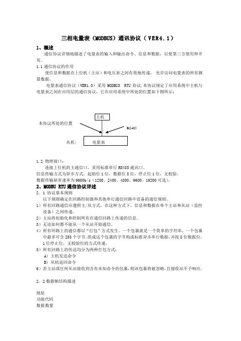
电量表通信协议(VER1.0)采用MODBUS RTU协议,本协议规定了应用系统中主机与电量表之间在应用层的通信协议,它在应用系统中所处的位置如下图所示:主机本协议所处的位置RS485从机: 电量表1.2 物理接口:连接上位机的主通信口,采用标准串行RS485通讯口。
信息传输方式为异步方式,起始位1位,数据位8位,停止位1位,无校验。
数据传输缺省速率为9600b/s(1200、2400、4800、9600、19200可选)。
2、MODBU RTU通信协议详述2.1 协议基本规则以下规则确定在回路控制器和其他串行通信回路中设备的通信规则。
1)所有回路通信应遵照主/从方式。
在这种方式下,信息和数据在单个主站和从站(监控设备)之间传递。
2)主站将初始化和控制所有在通信回路上传递的信息。
3)无论如何都不能从一个从站开始通信。
4)所有环路上的通信都以“打包”方式发生。
一个包裹就是一个简单的字符串,一个包裹中最多可含255个字节。
组成这个包裹的字节构成标准异步串行数据,并按8位数据位,1位停止位,无校验位的方式传递。
5)所有回路上的传送均分为两种打包方式:A) 主机发送命令B) 从机返回命令6)若主站或任何从站接收到含有未知命令的包裹,则该包裹将被忽略,且接收站不予响应。
2.2数据帧结构描述地址功能代码数据数量数据1...数据nCRC 16位校验3、传输格式(1)读数据命令主站发送命令:地址功能码寄存器起始地址寄存器个数CRC1 byte XX(见表1)2 byte 2 byte 2 byte正常应答返回:地址功能码数据区字节数数据区CRC16位校验1 byte XX(见表1) 1 byte .....2 byte异常应答返回:非法功能从站地址功能码异常码CRC16校验80H+原功能码01非法数据地址从站地址功能码异常码CRC16校验80H+原功能码02非法数据值从站地址功能码异常码CRC16校验80H+原功能码03帧格式(10位)起始位 D0 D1 D2 D3 D4 D5 D6 D7 停止位(2)、写数据命令主站发送命令:地址功能码寄存器起始地址寄存器个数数据区字节数写入的数据CRC1 byte XX(见表1)2 byte 2 byte 1 byte ..... 2 byte正常应答返回:地址功能码寄存器起始地址寄存器个数CRC16位校验1 byte XX(见表1) 2 byte 2 byte 2 byte异常应答返回:非法功能从站地址功能码异常码CRC16校验80H+原功能码01非法数据地址从站地址功能码异常码CRC16校验80H+原功能码02非法数据值从站地址功能码异常码CRC16校验80H+原功能码03帧格式(10位)起始位 D0 D1 D2 D3 D4 D5 D6 D7 停止位注:CRC检验码低位在前高位在后;寄存器地址、数据均为高位在前低位在后;4、参数信息数据地址描述说明40001 DI1状态1BIT 只读 (断开:0 合:1)40002 DI2状态1BIT 只读 (断开:0 合:1)40003 DI3状态1BIT 只读 (断开:0 合:1)40004 DI4状态1BIT 只读 (断开:0 合:1)40005 DI5状态1BIT 只读 (断开:0 合:1)40006 DI6状态1BIT 只读 (断开:0 合:1)40007 DI7状态1BIT 只读 (断开:0 合:1)40008 DI8状态1BIT 只读 (断开:0 合:1)40009 DI9状态1BIT 只读 (断开:0 合:1)40010 DI10状态1BIT 只读 (断开:0 合:1)40011 DI11状态1BIT 只读 (断开:0 合:1)40012 DI12状态1BIT 只读 (断开:0 合:1)40013 DI13状态1BIT 只读 (断开:0 合:1)40014 DI14状态1BIT 只读 (断开:0 合:1)40015 DI15状态1BIT 只读 (断开:0 合:1)40016 DI16状态1BIT 只读 (断开:0 合:1)40017 DI17状态1BIT 只读 (断开:0 合:1)40018 DI18状态1BIT 只读 (断开:0 合:1)40019 DI19状态1BIT 只读 (断开:0 合:1)40020 DI20状态1BIT 只读 (断开:0 合:1)40101 设备地址(出厂默认为1) 2 byte 读/写地址范围: 1 ~ 25440102 通讯波特率(出厂默认为19200) 2 byte 读/写数据范围: 0 ~ 4; 0表示1200速率; 1表示2400速率; 2表示4800; 3表示9600; 4表示19200;5、特殊命令:出厂默认地址为01;地址可设范围为01~fe; ff为广播地址,对所有设备都起作用,00为单机地址,在主机只连接一台设备时使用。
科研仪器 MD204L 数据采集 用户手册说明书
目录第一章产品概述 (1)1.1功能 (1)1.2一般规格 (1)1.3各部分名称 (2)1.4外型尺寸及安装方法 (4)第二章编辑软件TP200 (5)2.1 TP200基本概述 (5)2.2编辑用户画面 (5)2.3保存工程 (29)2.4下载画面 (30)2.5 导入旧工程 (30)第三章操作方法 (32)3.1联机通讯 (32)3.2切换画面 (32)3.3系统口令 (32)3.4修改数据 (33)3.5开关量控制 (34)第四章与PLC的连接方法 (35)4.1三菱FX系列 (35)4.2西门子S7-200系列 (35)4.3欧姆龙C系列 (36)4.4施耐德NEZA/TWIDO系列 (37)4.5 台达DVP系列 (38)4.6松下FP系列 (38)4.7 LG Master-K CNet系列 (39)4.8 LG系列 Modbus 协议 (40)4.9 LG Master-K 120S 编程口通讯 (41)4.10 FACON永宏系列 (41)4. 11 光洋S系列 (42)4.12 ECOSTEP 系列 (43)4.13 AB Micrologix系列 (44)4.14 MODBUS RTU/ASCII/EMERSON/RTU EXTEND (45)4.15 MODBUS SERVER (46)4.16 eView自由协议 (47)4.17 SAIA PCD S-BUS协议 (48)4.18 VIGOR PLC (49)4.19 EMERSON EC20系列PLC (49)4.20 KEYENCE KV系列PLC (50)MD204L V4用户手册V4.0.0 组态软件Release Note (51)附录1:自由协议文档 (56)附录2:其它注意事项 (58)第一章产品概述1.1功能MD204L是一个小型的人机界面,主要与各类PLC(或带通信口的智能控制器)配合使用,以文字或指示灯等形式监视、修改PLC内部寄存器或继电器的数值及状态,从而使操作人员能够自如地控制机器设备。
PLC与上位组态软件通讯设置Modbus

目录1 PLC与Intouch软件通讯设置 (2)1.1 利用Modbus TCP/IP协议的通讯设置 (2)1.1.1 IO Server软件配置 (2)1.1.2 软件编程设置 (4)1.1.3 IO Server状态监视 (5)1.2 利用Modbus Plus协议的通讯设置 (6)1.2.1 IO Server软件设置 (6)1.2.2 软件编程设置 (6)1.3 利用Modbus协议的通讯设置 (7)1.3.1 IO Server软件设置 (7)1.3.2 软件编程设置 (7)1.4 注意 (8)2 PLC与组态王软件通讯设置 (9)2.1 利用Modbus TCP/IP协议的通讯设置 (9)2.1.1 工程浏览器中通讯设置(即与PLC通讯时的相关设置) (9)2.1.2 软件编程设置 (13)2.1.3 数据状态监视 (17)2.2 利用Modbus Plus协议的通讯设置 (18)2.3 利用Modbus协议的通讯设置 (18)2.4 利用Unitelway协议的通讯设置 (19)3 PLC与iFIX软件通讯设置 (21)3.1 利用Modbus TCP/IP协议的通讯设置 (21)3.1.1 系统配置 (21)3.1.2 数据库标签定义 (26)3.1.3 软件编程 (28)3.2 利用Modbus协议的通讯设置 (30)4 施耐德PLC与WINCC通讯 (32)4.1Wincc和Quantum PLC通讯 (34)4.2WinCC和Premium PLC通讯 (45)4.3WinCC和第三方Modbus TCPIP设备通讯 (49)5 施耐德PLC与世纪星(Pastools)通讯 (51)5.1利用Modbus TCP/IP协议的通讯设置 (51)6 通讯注意事项 (54)1PLC与Intouch软件通讯设置Intouch软件中与施耐德PLC相关的驱动只有三种:Modbus TCP/IP、Modbus Plus、Modbus。
Eaton PXG产品系列Modbus通信和寄存器映射介绍说明书
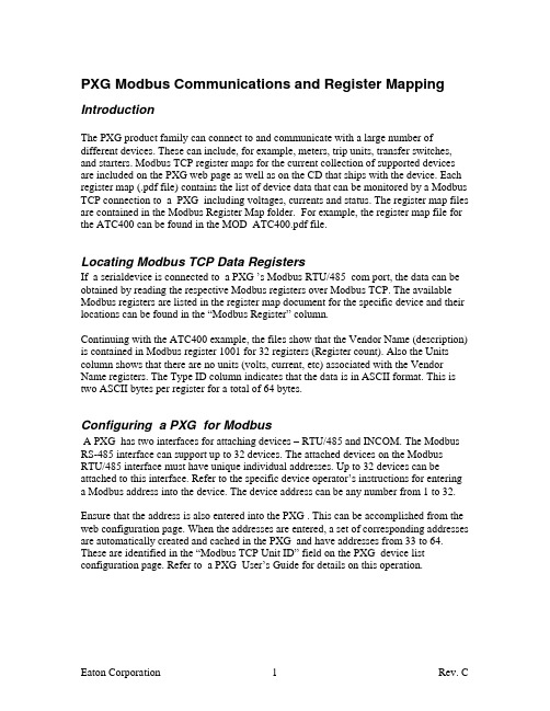
PXG Modbus Communications and Register Mapping IntroductionThe PXG product family can connect to and communicate with a large number of different devices. These can include, for example, meters, trip units, transfer switches, and starters. Modbus TCP register maps for the current collection of supported devices are included on the PXG web page as well as on the CD that ships with the device. Each register map (.pdf file) contains the list of device data that can be monitored by a Modbus TCP connection to a PXG including voltages, currents and status. The register map files are contained in the Modbus Register Map folder. For example, the register map file for the ATC400 can be found in the MOD_ATC400.pdf file.Locating Modbus TCP Data RegistersIf a serialdevice is connected to a PXG ’s Modbus RTU/485 com port, the data can be obtained by reading the respective Modbus registers over Modbus TCP. The available Modbus registers are listed in the register map document for the specific device and their locations can be found in the “Modbus Register” column.Continuing with the ATC400 example, the files show that the Vendor Name (description) is contained in Modbus register 1001 for 32 registers (Register count). Also the Units column shows that there are no units (volts, current, etc) associated with the Vendor Name registers. The Type ID column indicates that the data is in ASCII format. This is two ASCII bytes per register for a total of 64 bytes.Configuring a PXG for ModbusA PXG has two interfaces for attaching devices – RTU/485 and INCOM. The Modbus RS-485 interface can support up to 32 devices. The attached devices on the Modbus RTU/485 interface must have unique individual addresses. Up to 32 devices can be attached to this interface. Refer to the specific device operator’s instructions for entering a Modbus address into the device. The device address can be any number from 1 to 32. Ensure that the address is also entered into the PXG . This can be accomplished from the web configuration page. When the addresses are entered, a set of corresponding addresses are automatically created and cached in the PXG and have addresses from 33 to 64. These are identified in the “Modbus TCP Unit ID” field on the PXG device list configuration page. Refer to a PXG User’s Guide for details on this operation.Reading the Modbus TCP RegistersThe registers can be read by addressing the PXG s IP address and port (default port is 5021) using a Modbus TCP analyzer or software application. In general, set the analyzer program for RTU protocol and MODICON as the mod type. If you have the option, select 0-based addressing.When polling the device use the Modbus TCP Unit ID field address specified in the device list configuration. The number of registers should correspond to the register count on the spread sheet. Use function code 04 for reading the cached values in the PXG 400. Interpreting the Individual Modbus TCP Register MapsThe register maps describe the characteristics of individual registers for a specific device connected to a PXG .Modbus RegisterThis is simply the number of the starting register for the Modbus data. When the data spans several registers begin reading the data at this register.DescriptionThis is the basic name of the data contained in the register.Register CountThis is the number of registers that contain the data. Begin reading the registers at the addresses specified in the Modbus Register column.Type ID (Data Formats)Modbus analyzer or application programs usually provide an option for viewing various data types. Refer to your Modbus program documentation for detailed information on viewing data options.Not all data formats are available in all devices.A register is 16 bits (two bytes). The PXG 400 supports the following data types:•STRING or ASCII– A string of ASCII characters (two per register). Consult the Size parameter to find the string’s length for a given entry (it is a multiple of two so that entries are register-aligned).•FLOAT – A 32-bit IEEE754 floating point number. FLOATs are always two registers.•UINT – An unsigned integer. UINT16 - a 16 bit unsigned integer. Consult the Size parameter to find the integer’s size for a given entry (it is a multiple of twoso that entries are register-aligned).1 The default port 502 can be changed via the PXG 400’s web page.•TIME or DATE – The Time type (ymdhms) consists of six bytes (three registers) specifying the year, month, day, hour, minutes, and seconds. The data is stored in hexadecimal format and is best viewed by using the binary option and converting each byte to decimal.•BOOL – A binary (Boolean) value of 0 or 1. BOOL is usually assigned to discrete input alarms.Data AddressingIf a data type spans multiple registers (such as a FLOAT), lower addressed registers map to higher-order parts of the value. Within each register, data is in the mostsignificant bit first (MSB first) format.NOTE A Modbus register contains two bytes. Therefore, the number of registers containing the information can be obtained by dividing the bytes by two. Forexample, the vendor name can be obtained by reading 32 Modbus registers starting at register 1032.NOTE If a register is not supported in a particular device, an exception response is returned.UNITSThis column is just the description of the value in the register. If the value is numeric the units usually describe volts, amps, or power. Most string values have no units.A note on devices that support the Status registerMany of the supported devices return a numeric status that depends on the specific device. But generally, the status follows the following format:-1 means unknown status0 means off or open1 means on or closed2 means fault of tripped3 means an alarm condition exists。
MODBUS通讯协议-推荐下载

富的串口、网络资源、通用 GPIO 接口等,同时具有强大的处理能力。结合 ModBus 通讯协议软件,就可非常方便 地构成符合 ModBus 通讯规范的主控(Master)及设备(Slave)的应用平台。针对 ModBus 通讯的主从方式这一特 点,英创公司的 ModBus 通讯协议软件包分为两个可独立使用的部分,即“ModBus 主控协议软件”(简称 modbus_Master)以及“ModBus 设备方协议软件”(简称 modbus_Slave)。目前英创 ModBus 通讯协议软件运行于 WinCE 环境下,均以 C 函数加静态 LIB 库的形式提供给客户。其主要特征如下:
modbus_Master 和 modbus_Slave)中的 API 函数可以同时支持基于串口和 TCP 的 Modbus 协议,应用程序只需要 在调用初始化函数时,用不同参数区分即可,有关参数的说明请参见相应的头文件:modbus_Master.h 和 modbus_Slave.h
1、modbus_Master 的应用 作为 Modbus 客户端模式的应用,主要是准备请求并向服务器设备发送请求,并等待服务器的响应。在做此 类应用开发时,用户可参考 Modbus 标准文献以及被控设备的通讯接口数据手册,直接调用英创提供的 modbus_Master 软件包提供了相应的操作 API 函数,来完成对服务器设备的访问和控制。在进行此类应用开发时, 用户只需要包含 modbus_master.h/ modbus_master.lib 即可。
C2000-A1-PAX0200-EX1 使用说明书

2020年1月2日 更新C2000-A1-PAX0200-EX1 使用说明书RS485 ← 2AI0-20/4-20 mA远程 I/O 模块 — RS485 型模拟量模块深圳市中联创新自控系统有限公司Shenzhen United Innovation Automatic Control System Co., Ltd.24445679911121314141515151515151516161718181919212124242728目录目录1. 快速使用1.1. 使用前准备1.2. 设备接线1.3. 软件设置及设备调试1.3.1. 设备搜索及参数设置1.3.2. 设备调测2. 硬件说明2.1. 技术参数2.2. 产品外观2.3. 指示灯2.4. 端口说明2.5. 尺寸2.6. 安装方式3. 产品功能3.1. 输入信号采集3.1.1. AI 采集类型3.2. 其他功能3.2.1. AI 模块滤波参数3.2.2. AI 模块采样范围3.2.3. AI 原始值高(低)点标定值4. 软件操作4.1. 软件安装4.2. 软件界面及功能介绍4.3. 软件使用4.3.1. 设置设备串口参数4.3.2. 设备状态查看4.3.3. 设备状态控制5. 通信协议5.1. 寄存器列表5.2. 协议应用范例5.2.1. 读AI 工程量状态(0x03)6. 装箱清单7. 产品服务【版权声明】©2000 - 2020 中联创新版权所有【商标声明】及其它中联创新服务相关的商标均为深圳市中联创新自控系统有限公司及其关联公司所有。
本文档涉及的第三方主体的商标,依法由权利人所有。
【免责声明】本文档仅提供有关康耐德产品的信息。
本文档并未授予任何知识产权的许可,包括未以明示或暗示、以禁止发言或其他方式授予任何知识产权许可。
除深圳市中联创新自控系统有限公司在其产品的销售条款和条件中声明的责任之外,深圳市中联创新自控系统有限公司不承担任何其他责任;并且深圳市中联创新自控系统有限公司对康耐德产品的销售或使用不作任何明示或暗示的担保,包括对产品特定用途适用性、适销性、对任何专利权、版权或其他知识产权的侵权责任等,均不作担保。
沈阳新维自动化有限公司 AMDP D2 系列电动机保护器 MODBUS、RS-485 通讯说明书
7.10、AMDP-□/D2 系列电动机保护器7.10.1、MODBUS、RS-485通讯接口7.10.1.1、MODBUS、RS-485通讯接口的特点MODBUS通讯协议可基于RS-485通讯接口, RS-485通讯协议是基于RS-485通讯接口的自由通讯协议,两者都是主从型半双工通讯协议。
AMDP-□/D2 系列电动机保护器配有RS-485通讯接口,可以与DCS、PLC、上位计算机等可在RS-485通讯网络中作主站的设备进行MODBUS、RS-485通讯。
在RS-485通讯网络中,AMDP-□/D2 系列电动机保护器是从站。
主站(DCS、PLC、上位计算机等具有RS-485通讯接口且可做主站的设备)可通过电动机保护器的RS-485通讯接口利用MODBUS、RS-485通讯协议,读取电动机保护器的运行状态、A、B、C相电流、电动机保护器参数;修改电动机保护器参数。
7.10.1.2、AMDP-□/D2 系列电动机保护器MODBUS、RS-485通讯技术参数1、数据格式1个起始位、8个数据位、1个校验位(奇校验、偶校验、无校验)、1个或2个停止位;2、通讯速率300、600、1200、2400、4800、9600、19200、38400、57600 BPS;3、同一网段从站数量在RS-485通讯的同一网段中,可连接32台配有RS-485通讯接口的电动机保护器;4、同一网段通讯距离通讯距离与数据传输速率相关,电动机保护器配有的RS-485通讯接口,在波特率为9600 BPS 的速率下,可达1Km。
7.10.1.3、AMDP-□/D2 系列电动机保护器MODBUS、RS-485通讯网络布置1、DCS作主站的AMDP-□/D2 系列电动机保护器RS-485通讯网络布置DCSRS-4852、PLC作主站的AMDP-□/D2 系列电动机保护器RS-485通讯网络布置PLCRS-4853、计算机作主站的AMDP-□/D2 系列电动机保护器RS-485通讯网络布置RS-4857.10.1.4、AMDP-□/D2 系列电动机保护器 MODBUS 功能下表是AMDP-□/D2 系列电动机保护器 MODBUS 功能,AMDP-□/D2 系列电动机保护器 MODBUS 功能的详细介绍请参考《电动机保护器MODBUS通讯技术手册》。
BlueEye Ex-D Modbus通讯说明书
BlueEye™ Ex -D Modbus CommunicationThe BlueEye ™ Ex-D features RS485 Modbus communication, allowing the user to read measurement values,and configure the device according to individual preferences.BlueEye™ Ex -D Modbus Communication - RS485 settingsBlueEye™ Ex -D Modbus Communication – WiringConnect to the BlueEye TM Ex-D using either the full-duplex or the half-duplex RS485 Modbus configuration, as described in the wiring schematics below.Once connected, the device can be accessed via its default Modbus address: 18 (0x12 in hexadecimal format).BlueEye ™ Ex -D WiringModbusCommunication ProtocolMANUALBlueEye™ Ex-D Modbus Wiring SchematicsBlueEye™ Ex-D Modbus Communication – Holding registerThe device can be configured by modifying the holding register.Changes to the holding register will only take effect if the configuration passcode in register 40’050 is set to 27521. This passcode protection is used to avoid accidental modifications to the holding register, and it is recommended to set this register value to zero during normal operation.The holding register is described in the table below.BlueEye™ Ex-D Modbus Holding RegisterUnit Options TableBlueEye™ Ex-D Modbus Communication – Input registerThe measurement output can be read from the input register. The user has read-only access to the input register. The output is updated every second.Float32 data in the input register span 2 registers, as each register is 16bits wide. Consequently, a Float32 value must be calculated based on its two registers.Here is an example of the “word swap” procedure to calculate the WI (Float32) based on register 0 and 1:a. Read input register addr. 0 (lower addr.) → return 0x7e5db. Read input register addr. 1 (upper addr.) → return 0x4248c. Concatenate the two values: 0x42487e5dd. When interpreting this 32bits value as a Float32 (IEEE754) = 50.1234The input register is described in the below table.BlueEye™ Ex-D Modbus Input RegisterBlueEye™ Ex-D Modbus Communication – Status registersThe status registers provide the user with information concerning the overall device status. When the device is working correctly the registers should display nominal values.See below tables for a detailed overview of the status registers.BlueEye™ Ex-D Modbus Status1 RegisterBlueEye™ Ex-D Modbus Status2 Register。
BM300 电力智能监控仪表 操作手册说明书
警告!只能由专业电工进行安装。 Warning! Installation by person with electrotechnicalexpertise only. Warnung! Installation nur durch elektrotechnische Fachkraft. Avvertenza! Fare installare solo da un elettricista qualificato. Avertissement! Installation uniquement par des personnes qualifiées en électrotechnique. ¡Advertencia! La instalacióndeberáserrealizadaúnicamentepor electricistasespecializados. /lowvoltage/directives
起(抬起时用力不可过大,否则可能会使固定头断裂),另一只手的拇指按图中箭头 所示方向用力推,卡子即可取下。安装时,将装置于面板前方推放入安装孔内,然后 从后方沿装置的沟槽将安装卡安上。如图 2.1.2.3,两手分别按住装置的上下两面, 两拇指顶在卡子的两端,按箭头所示方向均匀用力前推,使卡子挤紧面板。两个安装 卡都完成安装后,装置将牢固地固定在面板上。
1.2 BM300 的特点
图 1.1.1 BM300 装置外形图
1.2.1 BM300 具有强大的数据采集和处理功能
支持三相三线制和三相四线制可选功能,具有三相电压、三相电流、总有功功率、总 无功功率、各相的有功及无功功率、功率因数、各相的功率因数、系统频率、总有功 电度、总无功电度、各相的有功电度和无功电度的测量与计算功能。
ModbusTCP通讯机制的探索
Modbus TCP通讯机制的探索发布时间:2022-03-21T08:14:55.800Z 来源:《福光技术》2022年3期作者:郭保杏[导读] 本文主要介绍了广西钢铁集团烧结厂综合原料场项目的施耐德M580系列PLC控制系统与上位机软件Wonderware 2017 System Platform(下文统称系统平台)的通讯连接建立;以及在使用过程中出现画面刷新延时高、甚至卡顿情况。
经过数月探索,依据系统平台软件运行日志及咨询软件厂家技术人员、PLC技术人员,逐步修改系统平台配置参数及PLC相关通讯参数,最终解决画面卡顿问题,实现系统平台软件长期稳定运行。
郭保杏广西钢铁集团有限公司烧结厂摘要:本文主要介绍了广西钢铁集团烧结厂综合原料场项目的施耐德M580系列PLC控制系统与上位机软件Wonderware 2017 System Platform(下文统称系统平台)的通讯连接建立;以及在使用过程中出现画面刷新延时高、甚至卡顿情况。
经过数月探索,依据系统平台软件运行日志及咨询软件厂家技术人员、PLC技术人员,逐步修改系统平台配置参数及PLC相关通讯参数,最终解决画面卡顿问题,实现系统平台软件长期稳定运行。
关键词:系统平台、施耐德、M580系列PLC一、项目背景随着工业信息化的不断进步,工厂的基础自动化建设已经成为提升企业核心竞争力的关键因素。
利用PLC系统进行工业设备的操作、状态监控以及通过一些智能系统、专家系统指导工艺,向PLC系统发送控制指令,已经成为目前阶段我们发展的主要方向和目标。
这直接关系着工厂生产力的提高和企业发展的关键竞争优势。
近年来,越来越多的公司都在加快构建自身的基础自动化建设,为了适应生产水平的需要和国际化的需要,积极参与国家信息化进程,提高管理水平,展现全新的企业形象。
广西钢铁集团有限公司烧结厂决定在综合原料场项目中结合智能化料场项目,设计全新的PLC控制系统,以适应当前信息化建设的需要。
- 1、下载文档前请自行甄别文档内容的完整性,平台不提供额外的编辑、内容补充、找答案等附加服务。
- 2、"仅部分预览"的文档,不可在线预览部分如存在完整性等问题,可反馈申请退款(可完整预览的文档不适用该条件!)。
- 3、如文档侵犯您的权益,请联系客服反馈,我们会尽快为您处理(人工客服工作时间:9:00-18:30)。
三相电量表(MODBUS)通讯协议(V E R4.1)
1、概述
通信协议详细地描述了电量表的输入和输出命令、信息和数据,以便第三方使用和开发。
1.1通信协议的作用
使信息和数据在上位机(主站)和电压表之间有效地传递,允许访问电量表的所有测量数据。
电量表通信协议(VER1.0)采用MODBUS RTU协议,本协议规定了应用系统中主机与电量表之间在应用层的通信协议,它在应用系统中所处的位置如下图所示:
主机
本协议所处的位置
RS485
从机: 电量表
1.2 物理接口:
连接上位机的主通信口,采用标准串行RS485通讯口。
信息传输方式为异步方式,起始位1位,数据位8位,停止位1位,无校验。
数据传输缺省速率为9600b/s(1200、2400、4800、9600、19200可选)。
2、MODBU RTU通信协议详述
2.1 协议基本规则
以下规则确定在回路控制器和其他串行通信回路中设备的通信规则。
1)所有回路通信应遵照主/从方式。
在这种方式下,信息和数据在单个主站和从站(监控设备)之间传递。
2)主站将初始化和控制所有在通信回路上传递的信息。
3)无论如何都不能从一个从站开始通信。
4)所有环路上的通信都以“打包”方式发生。
一个包裹就是一个简单的字符串,一个包裹中最多可含255个字节。
组成这个包裹的字节构成标准异步串行数据,并按8位数据位,1位停止位,无校验位的方式传递。
5)所有回路上的传送均分为两种打包方式:
A) 主机发送命令
B) 从机返回命令
6)若主站或任何从站接收到含有未知命令的包裹,则该包裹将被忽略,且接收站不予响应。
2.2数据帧结构描述
地址
功能代码
数据数量
数据1
...
数据n
CRC 16位校验
3、传输格式
(1)读数据命令
主站发送命令:
地址功能码寄存器起始地址寄存器个数CRC
1 byte XX(见表1)
2 byte 2 byte 2 byte
正常应答返回:
地址功能码数据区字节数数据区CRC16位校验
1 byte XX(见表1) 1 byte .....
2 byte
异常应答返回:
非法功能
从站地址功能码异常码CRC16校验
80H+原功能码01
非法数据地址
从站地址功能码异常码CRC16校验
80H+原功能码02
非法数据值
从站地址功能码异常码CRC16校验
80H+原功能码03
帧格式(10位)
起始位 D0 D1 D2 D3 D4 D5 D6 D7 停止位
(2)、写数据命令
主站发送命令:
地址功能码寄存器起始地址寄存器个数数据区字节数写入的数据CRC
1 byte XX(见表1)
2 byte 2 byte 1 byte ..... 2 byte
正常应答返回:
地址功能码寄存器起始地址寄存器个数CRC16位校验1 byte XX(见表1) 2 byte 2 byte 2 byte
异常应答返回:
非法功能
从站地址功能码异常码CRC16校验
80H+原功能码01
非法数据地址
从站地址功能码异常码CRC16校验
80H+原功能码02
非法数据值
从站地址功能码异常码CRC16校验
80H+原功能码03
帧格式(10位)
起始位 D0 D1 D2 D3 D4 D5 D6 D7 停止位
注:CRC检验码低位在前高位在后;寄存器地址、数据均为高位在前低位在后;
4、参数信息
数据地址描述说明
40001 DI1状态1BIT 只读 (断开:0 合:1)
40002 DI2状态1BIT 只读 (断开:0 合:1)
40003 DI3状态1BIT 只读 (断开:0 合:1)
40004 DI4状态1BIT 只读 (断开:0 合:1)
40005 DI5状态1BIT 只读 (断开:0 合:1)
40006 DI6状态1BIT 只读 (断开:0 合:1)
40007 DI7状态1BIT 只读 (断开:0 合:1)
40008 DI8状态1BIT 只读 (断开:0 合:1)
40009 DI9状态1BIT 只读 (断开:0 合:1)
40010 DI10状态1BIT 只读 (断开:0 合:1)
40011 DI11状态1BIT 只读 (断开:0 合:1)
40012 DI12状态1BIT 只读 (断开:0 合:1)
40013 DI13状态1BIT 只读 (断开:0 合:1)
40014 DI14状态1BIT 只读 (断开:0 合:1)
40015 DI15状态1BIT 只读 (断开:0 合:1)
40016 DI16状态1BIT 只读 (断开:0 合:1)
40017 DI17状态1BIT 只读 (断开:0 合:1)
40018 DI18状态1BIT 只读 (断开:0 合:1)
40019 DI19状态1BIT 只读 (断开:0 合:1)
40020 DI20状态1BIT 只读 (断开:0 合:1)
40101 设备地址(出厂默认为1) 2 byte 读/写地址范围: 1 ~ 254
40102 通讯波特率(出厂默认为
19200) 2 byte 读/写数据范围: 0 ~ 4; 0表示1200速率; 1表示2400速率; 2表示4800; 3表示9600; 4表示19200;
5、特殊命令:
出厂默认地址为01;地址可设范围为01~fe; ff为广播地址,对所有设备都起作用,00为单机地址,在主机只连接一台设备时使用。
批量设置波特率命令:
ff 06 9C A6 00 01 01 04 CRCL CRCH
单机读取设备地址:
00 03 9C A5 00 01 CRCL CRCH
注意:批量设置命令设备是不回复的;单机命令设备不用判断地址都回复。
6、命令举例:
在不知道设备地址的情况下通过单机读取设备地址来获取设备地址:
00 03 9C A5 00 01 BB A8
7、设备出厂后的默认波特率为19200;默认通讯地址为1;
8、在无法与本设备通讯的情况下请先用本包命令(获取设备地址: 00 03 9C A5 00 01 BB A8) 测试, 1.打开串口设备后选择连接到本设备的串口号; 2.校验位选择NONE,数据位选择8BIT,停止位选1; 3.先尝试19200的波特率与本设备通讯,如果不成功则再尝试9600,依此一直到1200;。