IRC自动化盒子,流量无优--autodl-irssi终极教程
aristo操作手册

aristo操作手册一、简介Aristo是一款功能强大的软件,旨在提供高效的操作和工作流程。
本操作手册将详细介绍Aristo的各项功能和如何使用它们。
二、安装与启动1. 下载Aristo软件安装包并双击打开。
2. 按照安装程序的指引,选择安装位置和必要的设置。
3. 完成安装后,双击桌面上的Aristo图标启动软件。
三、用户界面1. 菜单栏:包含各种功能选项,如文件、编辑、视图等。
2. 工具栏:提供快速访问操作的图标按钮。
3. 项目面板:显示当前项目和相关信息。
4. 编辑区域:用于编辑和查看文档内容。
四、基本操作1. 创建新项目:a) 单击菜单栏中的“文件”选项。
b) 选择“新建项目”并填写相关信息。
c) 单击“确定”按钮创建新项目。
2. 打开和保存项目:a) 单击菜单栏中的“文件”选项。
b) 选择“打开项目”或“保存项目”。
c) 浏览文件夹并选择相应的项目文件。
3. 添加和管理任务:a) 在项目面板中,单击“添加任务”按钮。
b) 输入任务名称和描述。
c) 对任务进行编辑和管理。
5. 导出文档:a) 单击菜单栏中的“文件”选项。
b) 选择“导出”并选择所需的文件格式。
c) 指定导出路径和文件名,单击“确定”按钮。
六、高级功能1. 自定义快捷键:a) 单击菜单栏中的“编辑”选项。
b) 选择“自定义快捷键”。
c) 在弹出的对话框中,设置所需的快捷键。
2. 多人协作:a) 单击菜单栏中的“编辑”选项。
b) 选择“共享”并填写协作成员的邮箱地址。
c) 设置权限并发送邀请。
3. 数据备份与恢复:a) 单击菜单栏中的“文件”选项。
b) 选择“备份”或“恢复”。
c) 指定备份或恢复的路径,并执行相应操作。
4. 数据同步:a) 在设置中启用“自动同步”选项。
b) 登录Aristo账户。
c) 在多个设备上登录相同的账户,即可实现数据同步。
七、常见问题及解决方法1. 无法启动软件:a) 确保已正确安装Aristo软件。
罗克韦尔自动化 FLEX I O 远程 I O 适配器模块 安装说明说明书
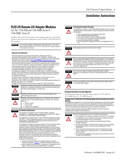
FLEX I/O Remote I/O Adapter Modules 1Publication 1794-IN098E-EN-P - January 2011Installation InstructionsFLEX I/O Remote I/O Adapter ModulesCat. No. 1794-ASB and 1794-ASBK Series E; 1794-ASB2, Series D(Modules with a K in the last position of the catalog number are conformally coated to meet noxious gas requirements of ISA/ANSI-71.040 1985 Class G3 Environment.)European Hazardous Location ApprovalThe following modules are European Zone 2 approved: 1794-ASB and 1794-ASBK Series E; 1794-ASB2, Series DDo not use these adapters (1794-ASB and 1794-ASBK Series E; 1794-ASB2, Series D) with the Classic PLC-5/15 or PLC-5/25 processors. Improper operation of the remote I/O can result.Important User InformationSolid state equipment has operational characteristics differing from those ofelectromechanical equipment. Safety Guidelines for the Application, Installation andMaintenance of Solid State Controls (Publication SGI-1.1 available from your local Rockwell Automation sales office or online at ) describes some important differences between solid state equipment and hard-wiredelectromechanical devices. Because of this difference, and also because of the wide variety of uses for solid state equipment, all persons responsible for applying this equipment must satisfy themselves that each intended application of this equipment is acceptable. In no event will Rockwell Automation, Inc. be responsible or liable for indirect or consequential damages resulting from the use or application of this equipment.The examples and diagrams in this manual are included solely for illustrative purposes. Because of the many variables and requirements associated with any particular installation, Rockwell Automation, Inc. cannot assume responsibility or liability for actual use based on the examples and diagrams.No patent liability is assumed by Rockwell Automation, Inc. with respect to use of information, circuits, equipment, or software described in this manual.Reproduction of the contents of this manual, in whole or in part, without written permission of Rockwell Automation, Inc., is prohibited.Throughout this manual we use notes to make you aware of safety considerations.Identifies information about practices or circumstances that can cause an explosion in a hazardous environment, which may lead to personal injury or death, property damage, or economic loss.Identifies information that is critical for successful application and understanding of the product.Identifies information about practices or circumstances that can lead to personal injury or death, property damage, or economic loss. Attentions help you:•identify a hazard •avoid a hazard•recognize the consequenceEnvironment and EnclosureThis equipment is intended for use in a Pollution Degree 2 industrialenvironment, in overvoltage Category II applications (as defined in IEC 60664-1), at altitudes up to 2000 m (6562 ft) without derating.This equipment is considered Group 1, Class A industrial equipment according to IEC/CISPR 11. Without appropriate precautions, there may be difficulties with electromagnetic compatibility in residential and other environments due to conducted and radiated disturbances.This equipment is supplied as open-type equipment. It must be mounted within an enclosure that is suitably designed for those specific environmentalconditions that will be present and appropriately designed to prevent personal injury resulting from accessibility to live parts. The enclosure must have suitable flame-retardant properties to prevent or minimize the spread of flame, complying with a flame spread rating of 5VA, V2, V1, V0 (or equivalent) if non-metallic. The interior of the enclosure must be accessible only by the use of a tool.Subsequent sections of this publication may contain additional information regarding specific enclosure type ratings that are required to comply with certain product safety certifications. In addition to this publication, see:•Industrial Automation Wiring and Grounding Guidelines, RockwellAutomation publication 1770-4.1, or additional installation requirements.•NEMA Standard 250 and IEC 60529, as applicable, for explanations of the degrees of protection provided by different types of enclosure.Preventing Electrostatic DischargeThis equipment is sensitive to electrostatic discharge, which can cause internal damage and affect normal operation. Follow these guidelines when you handle this equipment:•Touch a grounded object to discharge potential static.•Wear an approved grounding wriststrap.•Do not touch connectors or pins on component boards.•Do not touch circuit components inside the equipment.•Use a static-safe workstation, if available.•Store the equipment in appropriate static-safe packaging when not in use.Power wiring must be less than 10 m (33 ft) in length.FLEX I/O is grounded through the DIN rail to chassis ground. Use zinc plated yellow-chromate steel DIN rail to assure proper grounding. The use of other DIN rail materials (for example, aluminum or plastic) that can corrode, oxidize, or are poor conductors, can result in improper or intermittent grounding. Secure DIN rail to mounting surface approximately every 200 mm (7.8 in.) and use end-anchors appropriately.Do not remove or replace an adapter module while power is applied.Interruption of the backplane can result in unintentional operation or machine motion.To reduce susceptibility to noise, power analog modules and digital modules from separate power supplies.European Zone 2 Certification (The following applies when the product bears the Ex Marking)This equipment is intended for use in potentially explosive atmospheres as defined by European Union Directive 94/9/EC and has been found to comply with the Essential Health and Safety Requirements relating to the design and construction of Category 3 equipment intended for use in Zone 2 potentially explosive atmospheres, given in Annex II to this Directive.Compliance with the Essential Health and Safety Requirements has been assured by compliance with EN 60079-15 and EN 60079-0.Observe the following additional Zone 2 certification requirements:•This equipment is not resistant to sunlight or other sources of UV radiation.•This equipment must be installed in an enclosure providing at least IP54 protection when applied in Zone 2 environments.•This equipment shall be used within its specified ratings defined by Rockwell Automation.•Provision shall be made to prevent the rated voltage from being exceeded by transient disturbances of more than 40% when applied in Zone 2 environments.•Secure any external connections that mate to this equipment by using screws, sliding latches, threaded connectors, or other means provided with this product.•Do not disconnect equipment unless power has been removed or the area is known to be nonhazardous.2 FLEX I/O Remote I/O Adapter Modules Publication 1794-IN098E-EN-P - January 2011North American Hazardous Location ApprovalThe following modules are North American Hazardous Location approved: 1794-ASB and 1794-ASBK Series E; 1794-ASB2, Series D.Remote I/O Adapter 1794-ASB/E, 1794-ASBK/E, 1794-ASB2/DThese adapters are shipped configured for standard addressing mode. InStandard Addressing Mode, the 1794-ASB(K) series E adapter can be used as a replacement for 1794-ASB series A and B remote I/O adapters, and the 1794-ASB2 series D can be used for a replacement for 1794-ASB2 series A 2-slot remote I/O adapters.Installing Your Adapter ModuleMount on a DIN rail before installing the Terminal Base Units1.Hook the lip on the rear of the adapter onto the top of the DIN rail,and rotate the adapter module onto the rail.2.Press the adapter module down onto the DIN rail until flush. Lockingtab C will snap into position and lock the adapter module to the DIN rail.3.If the adapter module does not lock in place, use a screwdriver orsimilar device to move the locking tab down while pressing theadapter module flush onto the DIN rail, and release the locking tab to lock the adapter module in place. If necessary, push up on the locking tab to lock.4.Connect the adapter wiring as shown under “Wiring” later in thisdocument.Mount or Replace the Adapter on an Existing System1.Remove the RIO plug-in connector from the front of the adapter.2.Disconnect any wiring jumpered to the adjacent terminal base.3.Open the module latching mechanism and remove the module fromthe base unit to which the adapter will be attached.4.Push the FlexBus connector toward the right side of the terminal baseto unplug the backplane connection. (When fully retracted, you will see a raised dot on the connector).5.Release the adapter locking tab and remove the adapter module.The following information applies when operating this equipment in hazardous locations:Informations sur l’utilisation de cet équipement en environnements dangereux:Products marked "CL I, DIV 2, GP A, B, C, D" are suitable for use in Class I Division 2 Groups A, B, C, D, Hazardous Locations and nonhazardous locations only. Each product is supplied with markings on the rating nameplate indicating thehazardous location temperature code. When combining products within a system, the most adverse temperature code (lowest "T" number) may be used to help determine the overall temperature code of the system. Combinations of equipment in your system are subject to investigation by the local Authority Having Jurisdiction at the time of installation.Les produits marqués "CL I, DIV 2, GP A, B, C, D" ne conviennent qu'à une utilisation enenvironnements de Classe I Division 2 Groupes A, B, C, D dangereux et non dangereux. Chaque produit est livré avec des marquages sur sa plaque d'identification qui indiquent le code de température pour les environnements dangereux. Lorsque plusieurs produits sont combinés dans un système, le code de température le plus défavorable (code detempérature le plus faible) peut être utilisé pour déterminer le code de température global du système. Les combinaisons d'équipements dans le système sont sujettes à inspection par les autorités locales qualifiées au moment de l'installation.EXPLOSION HAZARD•Do not disconnect equipment unless power has been removed or the area is known to be nonhazardous.•Do not disconnect connections to this equipment unless power has been removed or the area is known to be nonhazardous. Secure any external connections that mate to this equipment by using screws, sliding latches, threaded connectors, or other means provided with this product.•Substitution of components may impair suitability for Class I, Division 2.•IIf this product contains batteries, they must only be changed in an area known to be nonhazardous.RISQUE D’EXPLOSION•Couper le courant ou s'assurer que l'environnemen t est classé non dangereux avant de débrancher l'équipement.•Couper le courant ou s'assurer que l'environnement est classé non dangereux avant de débrancher les connecteurs. Fixer tous les connecteurs externes reliés à cet équipement à l'aide de vis, loquets coulissants, connecteurs filetés ou autres moyens fournis avec ce produit.•La substitution de composants peut rendre cet équipement inadapté à une utilisation en environnement de Classe I, Division 2.•S'assurer que l'environnement est classé non dangereux avant de changer les piles.Component Identification 1Remote I/O Adapter Module 6Remote I/O cable connector 2Indicators7+V DC connections 3Communication reset button (PRL)8-V common connections 4Access door to switches S1 and S29FlexBus connector5Switches S1 and S2 (behind door)If you insert or remove the module while backplane power is on, an electrical arc can occur. This could cause an explosion in hazardous location installations. Be sure that power is removed or the area is nonhazardous before proceeding.If you connect or disconnect the communications cable with power applied to this module or any device on the network, an electrical arc can occur. This could cause an explosion in hazardous location installations. Be sure that power is removed or the area is nonhazardous before proceeding.For Class I Division 2 applications, use only Class I Division 2 listed or recognized accessories and modules approved for used within the 1794 platform.During mounting of all devices, be sure that all debris (metal chips, wire strands, etc.) is kept from falling into the module. Debris that falls into themodule could cause damage on power up.FLEX I/O Remote I/O Adapter Modules 3Publication 1794-IN098E-EN-P - January 20116.Before installing the new adapter, notice the notch on the right rear ofthe adapter. This notch accepts the hook on the terminal base unit. The notch is open at the bottom. The hook and adjacent connection point keep the terminal base and the adapter tight together, reducing the possibility of a break in communication over the backplane.plete the adapter mounting as shown below.8.If the adapter module does not lock in place, use a screwdriver orsimilar device to move the locking tab down while pressing theadapter module flush onto the DIN rail, and release the locking tab to lock the adapter module in place. If necessary, push up on the locking tab to lock.9.Reinstall the module in the adjacent terminal base unit.Connect the Wiring1.Connect the remote I/O cable to the removable remote I/Oconnector.2.Connect +V DC power to the left side of the lower connector,terminal A .3.Connect -V common to the left side of the upper connector,terminal B .4.Connections C and D are used to pass +V DC power (D) and -Vcommon (C) to the next module in the series (if required).Set the Addressing Mode Switches1.Lift the hinged switch cover on the front of the adapter to expose theswitches.2.Set the switches as shown below.3.Cycle power to the adapter after setting the switches.Do not wire more than 2 conductors on any single terminal.ConnectTo terminal Blue Wire - RIO 1Shield Wire - RIO SH Clear Wire - RIO2If you connect or disconnect wiring while the field-side power is on, an electrical arc can occur. This could cause an explosion in hazardous location installations.Be sure that power is removed or the area is nonhazardous before proceeding.Push down and in at the same time to lock the adapter to the DIN rail.When the adapter is locked onto the DIN rail, gently push the FlexBus connector into the adapter to complete the backplaneIf this is the last adapter, you must terminate the remote I/O link here. Use a terminating resistor connected across terminals 1 and 2. Refer to your processor manual for information on the size of the resistor.WARNINGWhen you change switch settings while power is on, an electrical arc can occur. This could cause an explosion in hazardous location installations. Be sure that power is removed or the area is nonhazardous before proceeding.ATTENTIONSome switches on this adapter differ from the switches on previous versions. Make certain that you identify each switch before setting.8 and 16-point Mode Switch SettingsWhen using this addressing modeAndMode Switch 2 S1-1Mode Switch 1 S2-5Mode Switch 0 S2-8Standard (as shipped)8 and/or 16-point modulesSee note 1ON ON Compact8-point modules OFF ON OFF 16-point modules ONONOFFComplementary See complementary table below.Primary Chassis 8-point modules OFFOFF ON Complementary ChassisONOFF ON Complementary See complementary table below.Primary Chassis 16-point modules OFF OFF OFF Complementary ChassisON OFF OFF 1In Standard mode, this switch retains its function as switch position 1 of rack addressing. In standard mode, the module is functionally interchangeable with 1794-ASB series A or B adapters.2In compact mode, 32-point modules appear as 8 or 16-point modules.3When programming block transfers, address analog modules as module 0 if switch S1-1 is on; module 1 if switch S1-1 is off.32-point Mode Switch SettingsWhen using thisaddressing modeAndMode Switch 0 S2-8Mode Switch 1 S2-5Mode Switch 2 S1-1ModeSwitch 3 S2-3Mode Switch 4 S2-4Standard – 328, 16 and/or 32-point modulesONONSee note 1OFFOFFComplementary – 324 FLEX I/O Remote I/O Adapter ModulesPublication 1794-IN098E-EN-P - January 2011Primary Chassis 8, 16 and/or 32-point modulesOFF OFF OFF OFF OFF Complementary ChassisOFF OFF ON OFF OFF 1In Standard – 32 mode, any module in the chassis occupies 32 input points and 32 output points in the input/output data table.2In Complementary – 32 mode, any module in the chassis occupies 32 input points or 32 output points in the input/output data table. If using 8 or 16-point modules,unused points in the data table are zeroed out.First I/O Group 1) (see Important)I/O Rack Number S1-8S1-7I/O Group S1-6…S1-1ON ON 0 (1st)Refer to addressing modetables.OFF ON 2 (2nd)ON OFF 4 (3rd)OFF OFF 6 (4th)1) In 32-point mode, starting quarter must be 0 (S1-8 and S1-7 on).S2-8Mode Switch 0Refer to mode selection switches, above.S2-7Hold Inputs S2-6Rack Fault Select ON Hold inputs ON Disabled (default)OFF Reset inputs OFF EnabledS2-5Mode Switch 1Refer to mode selection switches, munication Rate (32-point Mode Select)Processor Restart Lockout Hold Last State S2-4S2-3Bits/s S2-2S2-1ON ON 57.6k ON Restart ON Reset Outputs OFF ON 115.2k OFFLocked outOFFHold Last StateON OFF 230.4k OFFOFFAuto BaudUse only with 32-point modules.1)These switches used to put the adapter in 32-point mode and perform autobaud.1)Cycle power to the adapter or push the RESET button when the baud rate is changed in the scanner.32-point Mode Switch SettingsWhen using thisaddressing modeAndMode Switch 0 S2-8Mode Switch 1 S2-5Mode Switch 2 S1-1ModeSwitch 3 S2-3Mode Switch 4 S2-4FLEX I/O Remote I/O Adapter Modules 5Publication 1794-IN098E-EN-P - January 2011Complementary I/O Rack Number Switch Settings for PLC-5 Processors(refer to your processor documentation for all other processors) SpecificationsPrimary RackRack Number S1 Switch Position 1747-SN PLC-5654321Rack 0Not Valid ON ON ON ON ON OFF Rack 1Rack 1OFF ON ON ON ON OFF Rack 2Rack 2ON OFF ON ON ON OFF Rack 3Rack 3OFF OFF ON ON ON OFF Rack 4ON ON OFF ON ON OFF Rack 5OFF ON OFF ON ON OFF Rack 6ON OFF OFF ON ON OFF Rack 7OFFOFFOFFONONOFFComplementary RackRack Number S1 Switch Position 1747-SN PLC-5654321Rack 0Not Valid ON ON ON OFF ON ON Rack 1Rack 1OFF ON ON OFF ON ON Rack 2Rack 2ON OFF ON OFF ON ON Rack 3Rack 3OFF OFF ON OFF ON ON Rack 4ON ON OFF OFF ON ON Rack 5OFF ON OFF OFF ON ON Rack 6ON OFF OFF OFF ON ON Rack 7OFFOFFOFFOFFONONSpecifications – 1794-ASB/E, 1794-ASBK/E, and 1794-ASB2/D1794-ASB/E, 1794-ASBK/E1794-ASB2/DI/O capacity 8 modules 2 modulesPower supplyPower supply must be capable of providing a turn-on inrush surge current of 23 A (at 24V DC) for 2 ms for each adapter connected to the power supply.Input voltage range 19.2V…31.2 V DC, 450 mA Output voltage 5V DC, 640 mA Communication rate 57.6 Kbps 115.2 Kbps 230.4 KbpsIndicators Power – green; Adapter active – green; Adapter fault – red; Local fault – redDimensions (H x W x D)87 x 69 x 69 mm 3.4 x 2.7 x 2.7 inchesIsolation voltage 50V (continuous), Basic Insulation TypeType tested at 750V DC for 60 s, power to system, power to RIO, and RIO to systemCurrent draw330 mA at 24V DC; 450 mA max Power dissipation, max 4.6 WThermal dissipation, max1.7BTU/**********Enclosure type rating None (open-style)Wire sizePower and RIO connections:Single wire connection: 0.33... 2.5 mm 2 (22...12 AWG) solid or stranded copper wire rated at 75 °C (167 °F ) or greater 1.2 mm (3/64 in.) insulation maxDouble wire connection: 0.33... 1.3 mm 2 (22...16 AWG) solid or stranded (not intermixed) copper wire rated at 75 °C (167 °F ) or greater 1.2 mm (3/64 in.) insulation max Wire category (1)(1)Use this Conductor Category information for planning conductor routing. Refer to Industrial Automation Wiring and Grounding Guidelines, publication 1770-4.1.3 – on power ports2 – on communications ports Terminal screw torque 0.8 Nm (7 lb-in.)Remote I/O cable Belden 9463 or equivalent Remote I/O connector plugPart number 942029-03North American temp codeT4A IEC temp codeT4Publication 1794-IN098E-EN-P - January 2011 Supersedes Publication 1794-IN098D-EN-P- March 2005Copyright © 2011 Rockwell Automation, Inc. All rights reserved.Mounting DimensionsEnvironmental Conditions Temperature, operating IEC 60068-2-1 (Test Ad, Operating Cold), IEC 60068-2-2 (Test Bd, Operating Dry Heat),IEC 60068-2-14 (Test Nb, Operating Thermal Shock): 0…55 °C (32…131 °F)Temperature,surrounding air, max 55 °C (131 °F)Temperature, nonoperatingIEC 60068-2-1 (Test Ab, Un-packaged Non-operating Cold), IEC 60068-2-2 (Test Bb, Un-packaged Non-operating Dry Heat), IEC 60068-2-14 (Test Na, Un-packaged Non-operating Thermal Shock):-40…85 °C (-40…185 °F)Relative humidity IEC 60068-2-30 (Test Db, Un-packaged Damp Heat):5…95% non-condensingVibration IEC60068-2-6 (Test Fc, Operating): 5 g @ 10…500 HzShock, operating IEC60068-2-27 (Test Ea, Unpackaged shock): 30 gShock, nonoperating IEC60068-2-27 (Test Ea, Unpackaged shock): 50 gEmissions CISPR 11:Group 1, Class A (with appropriate enclosure)ESD immunity IEC 61000-4-2: 8 kV air discharges Radiated RF immunityIEC 61000-4-3:10 V/m with 1 kHz sine-wave 80%AM from 80…2000 MHz 10 V/m with 200 Hz 50% Pulse 100%AM at 900 MHz 10 V/m with 200 Hz 50% Pulse 100%AM at 1890 MHz 3 V/m with 1 kHz sine-wave 80%AM from 2000…2700 MHz EFT/B immunity IEC 61000-4-4:±2 kV at 5 kHz on power ports±2 kV at 5 kHz on communications ports Surge Transient Immunity IEC 61000-4-5:±2 kV line-earth(CM) on communications ports Conducted RF ImmunityIEC 61000-4-6:10 Vrms with 1 kHz sine-wave 80%AM from 150 kHz…80 MHzCertifications (when product is marked)(1)c-UL-usUL Listed Industrial Control Equipment, certified for US and Canada. See UL File E65584.UL Listed for Class I, Division 2 Group A,B,C,D Hazardous Locations, certified for U.S. and Canada. See UL File E194810.CSA CSA Certified Process Control Equipment. See CSA File LR54689C.CSA Certified Process Control Equipment for Class I, Division 2 Group A,B,C,D Hazardous Locations. See CSA File LR69960C.CEEuropean Union 2004/108/EC EMC Directive, compliant with: EN 61326-1; Meas./Control/Lab., Industrial Requirements EN 61000-6-2; Industrial Immunity EN 61000-6-4; Industrial EmissionsEN 61131-2; Programmable Controllers (Clause 8, Zone A & B)C-Tick Australian Radiocommunications Act, compliant with: AS/NZS CISPR 11; Industrial EmissionsExEuropean Union 94/9/EC ATEX Directive, compliant with:EN 60079-15; Potentially Explosive Atmospheres, Protection "n" EN 60079-0; General Requirements II 3 G Ex nA IIC T4 XPublicationsInstallation Instructions 1794-IN098; User Manual 1794-UM009(1)See the Product Certification link at for Declarations of Conformity, Certificates, and other certificationdetails.。
OMEGA OME-WISE-7115 智能PAC控制器用户指南说明书

OME-WISE-7000 SERIESWeb-Based IntelligentPAC Controllerse-mail:**************For latest product manuals:User’s Guide®OME-WISE-7115It is the policy of OMEGA Engineering, Inc. to comply with all worldwide safety and EMC/EMI regulations that apply. OMEGA is constantly pursuing certification of its products to the European New Approach Directives. OMEGA will add the CE mark to every appropriate device upon certification.Benelux:Toll-Free: 0800 099 3344TEL: +31 20 347 21 21FAX: +31 20 643 46 43e-mail:**************Czech Republic:Frystatska 184733 01 Karviná, Czech Republic Toll-Free: 0800-1-66342TEL: +420-59-6311899FAX: +420-59-6311114e-mail:*****************France:Toll-Free: 0850 541038TEL: 01 57 32 48 17FAX: 01 57 32 48 18e-mail:***************Servicing Europe:Servicing AsiaU.S.A. and Canada:Sales Service: 1-800-826-6342/1-800-TC-OMEGA ®Customer Service: 1-800-622-2378/1-800-622-BEST ®Engineering Service: 1-800-872-9436/1-800-USA-WHEN ®China:1698 Yishan Road, Unit 102, Minhang DistrictShanghai, China 201103Hotline: 800 819 0559/400 619 0559e-mail:*************.comU.S.A.: ISO 9001 CertifiedOMEGA Engineering, Inc., One Omega Drive P.O. Box 4047, Stamford, CT 06907-0047 USA Toll-Free: 1-800-826-6342TEL: (203) 359-1660 FAX: (203) 359-7700e-mail:**************Servicing North America:For immediate technical or application assistance:Mexico/Latin America:TEL: 001 (203) 359-1660FAX: 001 (203) 359-7700e-mail:*****************Germany/Austria:Daimlerstrasse 26D-75392 Deckenpfronn, Germany Toll-Free************TEL: +49 (0) 7056 9398-0FAX: +49 (0) 7056 9398-29e-mail:*************United Kingdom: ISO 9001 CertifiedOMEGA Engineering Ltd.One Omega DriveRiver Bend Technology Centre, Northbank Irlam, Manchester M44 5BD England Toll-Free: 0800-488-488TEL: +44 (0) 161 777-6611FAX: +44 (0) 161 777-6622e-mail:**************.ukCanada:976 Bergar, Laval (Quebec)H7L 5A1, CanadaToll-Free: 1-800-826-6342TEL: (514) 856-6928 FAX: (514) 856-6886e-mail:*************Table of Contents1Overview (2)2Install/Uninstall OME-WISE-7000 Rule Utility (3)2.1Install OME-WISE-7000 Rule Utility (3)2.2Execute OME-WISE-7000 Rule Utility (4)2.3Uninstall OME-WISE-7000 Rule Utility (5)3Import Rule from a OME-WISE-7000 module to PC (7)4Export Rule from PC to a OME-WISE-7000 module (9)1 OverviewOME-WISE-7000 Rule Utility is an easy-to-use software tool specially designed for OME-WISE-7000 controller, it enables user to perform the following operations:●Import OME-WISE-7000 IF-THEN-ELSE Rule file from aOME-WISE-7000 module to PC●Export IF-THEN-ELSE Rule file from PC to a remoteOME-WISE-7000 moduleBy OME-WISE-7000 Rule Utility, the user can easily retrieve the IF-THEN-ELSE Rule file from a specific OME-WISE-7000 module and this file can be copied to multiple OME-WISE-7000 modules that require the same Rule file, therefore, there is no need to set up rules for each OME-WISE-7000 module individually.2 Install/Uninstall OME-WISE-7000 Rule Utility2.1 Install OME-WISE-7000 Rule UtilityFollow the steps below to install OME-WISE-7000 Rule Utility:●Obtain the OME-WISE-7000 Rule Utility setup file(OME-WISE-7000 Rule Utility Setup 1.x.exe).●Double click the setup file to install the file, you will see awindow pop up as below, click [Next] to continue.●Choose the installation location to install ME-WISE-7000 RuleUtility. Click [Install] to start the installation.●The installation progress will be shown as below; please waittill the installation is completed.●When the installation is completed, click [Finish] to close theprocess.2.2 Execute OME-WISE-7000 Rule UtilityFollow the steps below to execute OME-WISE-7000 Rule Utility:●Taking Windows XP as an example: click [Start] →[AllPrograms] → [OMEGA]→ [OME-WISE-7000 Rule Utility], andthen click “OME-WISE-7000 Rule Utility”under the[OME-WISE-7000 Rule Utility] category to start the program.2.3 Uninstall OME-WISE-7000 Rule UtilityFollow the steps below to uninstall OME-WISE-7000 Rule Utility:●Click [Start]→ [All Programs]→[OMEGA] →[OME-WISE-7000Rule Utility], and then click “Uninstall” under the [OOME-WISE-7000 Rule Utility] category.●You will see a window pop up as below, click [Next] tocontinue.●Click [Uninstall] to uninstall the program.When the uninstall process is completed, click [Finish] to finish the uninstallation.3 Import Rule from a OME-WISE-7000 module to PCFollow the steps below to import Rule from a OME-WISE-7000 module to PC.from the dropdown list.window to select the location for rule file saving operation.2. The selected directory path will be shown in the middle of the utilitySTEP 4: Import WISE Rule4 Export Rule from PC to a OME-WISE-7000 moduleFollow the steps below to export Rule from PC to a OME-WISE-7000 module.dropdown list.Input your OME-WISE-7000 module IP Address in the text box.WARRANTY/DISCLAIMEROMEGA ENGINEERING, INC. warrants this unit to be free of defects in materials and workmanship for a period of 13 months from date of purchase. OMEGA’s WARRAN TY adds an additional one (1)month grace period to the normal one (1) year product warranty to cover handling and shipping time. This ensures that OMEGA’s customers receive maximum coverage on each product.If the unit malfunctions, it must be returned to the factory for evaluation. OMEGA’s Customer Service Department will issue an Authorized Return (AR) number immediately upon phone or written request.Upon examination by OMEGA, if the unit is found to be defective, it will be repaired or replaced at no charge. OMEGA’s WARRANTY does not apply to defects resulting from any action of the purchaser,including but not limited to mishandling, improper interfacing, operation outside of design limits,improper repair, or unauthorized modification. This WARRANTY is VOID if the unit shows evidence of having been tampered with or shows evidence of having been damaged as a result of excessive corrosion; or current, heat, moisture or vibration; improper specification; misapplication; misuse or other operating conditions outside of OMEGA’s control. Components in which wear is not warranted,include but are not limited to contact points, fuses, and triacs.OMEGA is pleased to offer suggestions on the use of its various products. However, OMEGA neither assumes responsibility for any omissions or errors nor assumes liability for any damages that result from the use of its products in accordance with information provided by OMEGA, either verbal or written. OMEGA warrants only that the parts manufactured by the company will be as specified and free of defects. OMEGA MAKES N O OTHER WARRAN TIES OR REPRESEN TATION S OF AN Y KIN D WHATSOEVER,EXPRESSED OR IMPLIED, EXCEPT THAT OF TITLE, AN D ALL IMPLIED WARRAN TIES INCLUDING ANY WARRANTY OF MERCHANTABILITY AND FITNESS FOR A PARTICULAR PURPOSE ARE HEREBY DISCLAIMED. LIMITATION OF LIABILITY: The remedies of purchaser set forth herein are exclusive, and the total liability of OMEGA with respect to this order, whether based on contract, warranty, negligence, indemnification, strict liability or otherwise, shall not exceed the purchase price of the component upon which liability is based. In no event shall OMEGA be liable for consequential, incidental or special damages.CONDITIONS: Equipment sold by OMEGA is not intended to be used, nor shall it be used: (1) as a “Basic Component” under 10 CFR 21 (NRC), used in or with any nuclear installation or activity; or (2)in medical applications or used on humans. Should any Product(s) be used in or with any nuclear installation or activity, medical application, used on humans, or misused in any way, OMEGA assumes no responsibility as set forth in our basic WARRAN TY / DISCLAIMER language, and,additionally, purchaser will indemnify OMEGA and hold OMEGA harmless from any liability or damage whatsoever arising out of the use of the Product(s) in such a manner.RETURN REQUESTS/INQUIRIESDirect all warranty and repair requests/inquiries to the OMEGA Customer Service Department.BEFORE RETURNING ANY PRODUCT(S) TO OMEGA, PURCHASER MUST OBTAIN AN AUTHORIZED RETURN (AR) NUMBER FROM OMEGA’S CUSTOMER SERVICE DEPARTMENT (IN ORDER TO AVOID PROCESSIN G DELAYS). The assigned AR number should then be marked on the outside of the return package and on any correspondence.The purchaser is responsible for shipping charges, freight, insurance and proper packaging to prevent breakage in transit.FOR WARRANTY RETURNS, please have the following information available BEFORE contacting OMEGA:1.Purchase Order number under whichthe product was PURCHASED,2.Model and serial number of the productunder warranty, and3.Repair instructions and/or specificproblems relative to the product.FOR NON-WARRANTY REPAIRS,consult OMEGA for current repair charges. Have the followinginformation available BEFORE contacting OMEGA:1. Purchase Order number to cover the COST of the repair,2.Model and serial number of theproduct, and3.Repair instructions and/or specific problemsrelative to the product.OMEGA’s policy is to make running changes, not model changes, whenever an improvement is possible. This affords our customers the latest in technology and engineering.OMEGA is a registered trademark of OMEGA ENGINEERING, INC.Where Do I Find Everything I Need for Process Measurement and Control?OM EGA…Of Course!Shop online at TEMPERATUREThermocouple, RTD & ThermistorProbes, Connectors, Panels &AssembliesWire: Thermocouple, RTD &ThermistorCalibrators & Ice Point ReferencesRecorders, Controllers & ProcessMonitorsInfrared Pyrometers PRESSURE, STRAIN AND FORCE Transducers & Strain Ga u gesLoad Cells & Pressure Ga u gesDisplacement TransducersInstrumentation & Accessories FLOW/LEVELRotameters, Gas Mass Flowmeters &Flow ComputersAir Velocity IndicatorsTurbine/Paddlewheel SystemsTotalizers & Batch ControllerspH/CONDUCTIVITYpH Electrodes, Testers & AccessoriesBenchtop/Laboratory MetersControllers, Calibrators, Simulators & PumpsIndustrial pH & ConductivityEquipment DATA ACQUISITIONData Acquisition & EngineeringSoftwareCommunications-Based AcquisitionSystemsPlug-in Cards for Apple, IBM &CompatiblesDatalogging SystemsRecorders, Printers & Plotters HEATERSHeating CableCartridge & Strip HeatersImmersion & Band HeatersFlexible HeatersLaboratory Heaters ENVIRONMENTAL MONITORING AND CONTROL Metering & Control InstrumentationRefractometersPumps & TubingAir, Soil & Water MonitorsIndustrial Water & WastewaterTreatmentpH, Conductivity & Dissolved Oxygen Instruments。
NetMRI网络设备自动化管理与配置命令脚本(CCS)教程说明书

Dave SignoriSenior Director, Product ManagementNetwork Insight and NetMRISif Baksh Systems EngineerJohn BelamaricSoftware ArchitectCloud and Network AutomationCustomizing NetMRI NetworkChanges with ConfigurationCommand Scripting (CCS)Agenda•Why script and what scripting options are available in NetMRI •CCS Script Sections•Variables•Lists•Triggers•Filters•Operators•Other CCS Commands and Statements•Viewing, Adding, and Running CCS Scripts•Community Site and TABWhy Use Scripting?•Scripts:•Automate changes to infrastructure devices•Ensure consistent changes•Can be scheduled to run at specific times•Can be triggered to respond to specific events•Scripting reduces the risk of errors being made during execution •No fat fingering•No instant mistakes•Other features to consider before you script …•Config Templates•Config Search•RulesScripting Languages Supported •Focus of this tutorial:•CCS (Change Control Scripting)•Is a proprietary, high-level scripting language designed for network admins •Primary goal is to convert device-specific commands into repeatable tasks •Also supported:•Perl:•Is a general purpose, high-level scripting language•It has a large collection of 3rd party libraries and modules•It has powerful pattern matching and text processing featuresCCS SectionsSection MandatoryScript-Filter XAction XAction-FilterAction-Commands XScript-VariablesOutput-TriggersTriggerTrigger-FilterTrigger-VariablesTrigger-TemplateTrigger-CommandsCCS Sections -SampleSection MandatoryScript-Filter XAction XAction-FilterAction-Commands XScript-VariablesOutput-TriggersTriggerTrigger-Filter Trigger-Variables Trigger-Template Trigger-Commands Using these sectionsSample: Reset Password•Reset Password commands can be written as a CCS script as follows: Script-Filter:$Vendor eq "Cisco" and $sysDescr like /IOS/Script-Variables:$username word "User Name"$password password "New Password"# # # # # # # # # ## This is a commentAction:Set IOS User PasswordAction-Commands:config terminalusername $username password 0 $passwordexitwrite memory Prompt user to type in anusername and passwordOnly run on Cisco IOS devicesExecute commandsSample: Reset Password •The mandatory sections are highlighted in Red •The optional sections are highlighted in BlueScript-Filter:$Vendor eq "Cisco" and $sysDescr like /IOS/ Script-Variables:$username word "User Name"$password password "New Password" # # # # # # # # # ## This is a commentAction:Set IOS User PasswordAction-Commands:config terminalusername $username password 0 $passwordexitwrite memory RequiredRequired Required OptionalVariables•Temporary holding place•Declared using a dollar sign ($) e.g. $username•The value can change during the life of the script•Are global in scope. Available in all sections.•Are updated using the SET: directive•Three types of variables:•Script-Variables: prompt the user at runtime•Trigger-Variables: populated from output of a previous section•Well-Known variables: bundled with NetMRI like $Vendor, $Model, and $Version •When declaring a variable, you must specify a data type•i.e. number (integer), text (string), true/false (boolean)•Regex•$one_digit/^[1-9]$/•Predefined Regex•word, ipaddress, url, phoneno, zipcode, emailLists•CCS Scripts can reference a built-in file called a List. Think of it as a light-weight database.•Use the command getListValue to get the content of the List.•Lists can be created (or imported) under: Config Management -> Job Management -> ListsReading from a List•We use getListValue() to read from the List.SET: $reset= getListValue (Authorized_Users,username,“alice ”,default_passwd,NULL)•Look up from the List Authorized_Users , where username equals “alice ”, and return the corresponding password.•If the user “alice ” cannot be found, return NULL as the password.•Based on the List we defined, we expect to get the password “inW0nderl@nd ” for the user “alice ”.role username default_passwdnew_hire alice inW0nderl@nd new_hireNeoT@keTheRedPillSample with List: Reset Password Script-Filter:$Vendor eq "Cisco" and $sysDescr like /IOS/Script-Variables:$user word “Enter username to reset password"Action:Get default password of a single user from List Authorized_UsersAction-Commands:SET: $reset = getListValue(Authorized_Users,username,$user,default_passwd, “Nope”) Action-Commands: {$reset ne “Nope”}config terminalusername $user password 0 $resetendwr memTriggers•Mini script that only handles a single iteration of a loop•Action section runs, produces output, send it to the Trigger •Trigger section runs, reading in information as input, uses Trigger-Template to extract what’s necessary.•Runs commands in Trigger-Commands using the information extractedCCS Sections –Trigger SampleSection MandatoryScript-Filter XAction XAction-FilterAction-Commands XScript-VariablesOutput-TriggersTriggerTrigger-Filter Trigger-Variables Trigger-Template Trigger-Commands Using these sectionsTriggers•Action-Commands generates a list of output, and calls the Trigger to process the entire list, one item at a time.•Trigger-Commands defines what specific commands are run against each item of the list.•Take the familiar CLI commands sh run | inc username for example, “sh run”is like the Action-Commands, and sends the output to “inc username” to filter out just the usernames.Script-Filter:$Vendor eq "Cisco" and $sysDescr like /IOS/Script-Variables:$user word“Enter username to reset password”Action:Get existing usernamesAction-Commands:show run | inc usernameOutput-Triggers:Update Password# # # # # # # # # # #Trigger:Update PasswordTrigger-Variables:$existing_user wordTrigger-Template:username [[$existing_user]].+password 0.+Trigger-Commands:SET $reset = getListValue(Authorized_Users,username,$existing_user,default_passwd,NULL) conf tusername $existing_user password 0 $resetendwr mem Action, sends output to “Update Password” TriggerTrigger-Template extracts actual username from “show run “ inc username”Execute commands on theusernameScript-Filter:$Vendor eq "Cisco" and $sysDescr like /IOS/Script-Variables:$user word“Enter username to reset password”Action:Get existing usernamesAction-Commands:show run | inc usernameOutput-Triggers:Update Password# # # # # # # # # # #Trigger:Update PasswordTrigger-Variables:$existing_user wordTrigger-Template:username [[$existing_user]].+password 0.+Trigger-Commands:SET $reset = getListValue(Authorized_Users,username,$existing_user,default_passwd,NULL) Trigger-Commands:{$reset ne NULL}conf tusername $existing_user password 0 $resetendwr mem Action, sends output to “Update Password” TriggerTrigger-Template extracts actual username from “show run “ inc username”Execute commands on theusernameFilters•The {} is used as a filter to restrict execution.•Action-Commands and Trigger-Commands can be extended to specify optional filter criteria, restricting execution to cases where specific conditions exist.Example 1:Action-Commands: { $Vendor eq“Cisco” }show interfacesExample 2:Trigger-Commands: { $existing_user eq“Neo” }config tusername $existing_user password 0 $resetFilter Sections•Action-Filter and Trigger-Filter sections can also be used to apply the filter to the entire Action or Trigger section.Example 1:Action-Filter:$Vendor eq“Cisco” show interfacesExample 2:Trigger-Filter:$existing_user eq“Neo”Filters•Filters grant more flexibility and help optimize your code:•They work like an if-then, unless, or case statement•They can be written in two ways:Action:Show Running Config Action-Filter:$Vendor eq“Cisco”Action-Commands:show run | inc username Action:Update Logging DestinationAction-Commands {$sysDescr like /IOS/} logging 205.201.59.69Action-Commands {$sysDescr like /NX-OS/} logging server 205.201.59.69Action-Commands {$sysDescr like /SRX/} set system syslog host 205.201.59.69 any anyOperators•There are several ways to compare two variables•Here are four common approaches:Expressioneq ne in like Definition A equal to B A not equal to B A in list that follows A is similar to BExample Trigger-Commands:{$user eq“Neo”}Action-Commands:{$user ne “admin”}Action-Commands:{$user in[“Neo”,”alice”,”Morpheus”]}Trigger-Commands:{$user like /lic/}Notes Will execute if useris “Neo”Will execute if user isnot “admin”Will execute if user isNeo, alice, or MorpheusWill execute if theusername contains“lic”: either “alice”or “click”Assignment vs. Comparison•The =symbol is NOT the same as the eq comparison operator.•Assignment:•When we use =, we are taking whatever is B and copying it to A:Example: SET: $A = “no”•Comparison:•When we use eq, we are making an evaluation that ends in true or false, by comparing A to B:Example: { $A eq“no” }Putting It All Together -State Variable SampleScript-Filter:$Vendor eq "Cisco" and $sysDescr like /IOS/Script-Variables:$role word “Enter the role, such as new_hire ”Action:Get existing usernamesAction-Commands:show run | inc usernameSET: $ChangesMade = “no”Output-Triggers:Delete user# # # # # # # # # # #Trigger:Delete userTrigger-Variables:$existing_user wordTrigger-Filter:$existing_user ne “admin”Trigger-Template:username [[$existing_user]].+password 0.+Trigger-Commands:SET: $user_role = getListValue(Authorized_Users,username,$existing_user,role,NULL)Trigger-Commands: { $ChangesMade eq “no” and $user_role eq $role }conf tSET: ChangesMade = “yes”Initialize $ChangesMade to “no”Set $ChangesMade to “yes”State Variable Sample (continued)Trigger-Commands: { $user_role eq $role }no username $existing_userIterations# # # # # # # # # # #Action:Write to memory if changes were madeAction-Commands: { $ChangesMade eq “yes” }endwr memOnly execute if$ChangesMade is “yes”Other CCS Commands•Table below summarizes other CCS commands. For more details, refer to the Network Automation CSS Scripting Guide.Command DescriptionDEBUG Provides a mechanism to check whether or not a loop is entered or a statement is executed. Place DEBUG statement in front of the operation to check, and a debug icon will appear next to it if it would be executed.GET-CONFIGS Provides a mechanism to ensure Network Automation has the most up-to-date configurations from the network devices.LOG-INFOGenerates log messages to be sent to the appropriate log facilities, and goes into the standard Network Automation logging.LOG-WARNINGLOG-ERRORLOG-DEBUGPRINT Allows the printing of simple text strings (similar to the C “printf” command) and the printing of values within variables in CCS scripts to output text files.SKIPERROR Turns off error handling for script attributes when an error may appear from the acted-upon device, potentially preventing further job execution.SLEEP Pauses script execution for a specified number of seconds.EXPR Evaluate expressions, discussed next.Comments•Anything after the #symbol is ignored by the script•Use this to add human-readable comments so people reading the script (could be yourself later) understand the code.•For example:Action-Commands:# get current list of network interfaces to decide# which ones to disable# -Neo 04/25/2015DEBUG: Statement•Placing the DEBUG: directive in front of any statement will cause CCS to only print it out in the session log, but not execute the command.•For example:Action-Commands:DEBUG: conf tDEBUG: no username $usernameDEBUG: endDEBUG: wr memOperatorsOperator DescriptionA| B A if it is neither null nor 0, otherwise BA& B A if neither argument is null or 0, otherwise 0A <B A is less than BA <=B A is less than or equal to BA =B A is equal to BA !=B A is not equal to BA >=B A is greater than or equal to BA >B A is greater than BA +B Arithmetic sum of A and BA –B Arithmetic difference of A and BA *B Arithmetic product of A and BA /B Arithmetic quotient of A divided by BA %B Arithmetic remainder of A divided by BEXPR Command•EXPR performs more advanced comparison and evaluations •For example, increase $A by 1 (useful for iterating) EXPR: $A = $A + 1•Or compute the product of $A times $BEXPR: $A = $A * $BViewing, Adding, and Running CCS Scripts •Config Management -> JobManagement -> Scripts•Click Add to createAdding New CCS Script Levels Low, Medium, and High, indicatethe permission level needed to executethe scriptCategory is anything you want totype in that helps you organizescriptsName of scriptBody of CCS scriptRunning CCS Scripts•Config Management -> Job Management -> Scripts -> Run nowViewing Status and Job Details •Config Management -> Job Management -> Job HistoryViewing Status and Job DetailsCustomer Participation OpportunitiesTechnical Advisory Boards•10 TABs including NetMRI and Network Insight•Roadmap and early look at pre-releasedfeatures•Input for future enhancements•Best practices•First NetMRI session held on May 12th•Request membership at the Infoblox CommunitySite。
辛迪控制系统SIMATIC PCS neo功能库手册说明书
5
Monitoring blocks
6
Controller blocks
7
Motor and valve blocks
8
Interlock blocks
9
Mathematical block
10
Counter blocks
11
Digital logic blocks
12
Services
13
14 TCP communication blocks
SIMATIC SIMATIC PCS neo SIMATIC Process Function Library (V3.0)
Function Manual
About this document
1
Deployment conditions
2
Basics
3
Library structure
4
Operator control blocks
CAUTION
indicates that minor personal injury can result if proper precautions are not taken.
NOTICE
indicates that property damage can result if proper precautions are not taken. If more than one degree of danger is present, the warning notice representing the highest degree of danger will be used. A notice warning of injury to persons with a safety alert symbol may also include a warning relating to property damage.
ControlLogiix手册

允许定义1个,亦可以不定义。
•
周期型任务 指的是定时中断执行的逻辑程序,周期性的
执行任务,须定义周期时间,要设定优先级别,最多可以定义
31个。
•
事件触发型任务 指的是事件触发引起的任务调用,事件触
发可以是外部输入点变化引起(如同PLC5/SLC500),也可以由
Consumed 标签引起或直接指令调用引起,还可以由运动控制
6
ControlLogix系统概述(4)
Logix 系列控制器类型
• ControlLogix • FlexLogix • CompactLogix • SoftLogix • DriveLogix
7
ControlLogix系统概述(5)
ControlLogix系统网络类型
• EtherNet/IP • ControlNet • DeviceNet • DH+/RIO • DH485/串口 • 第三方通信
-- 直连的数据采集 -- OPC数据的采集 -- 优化的数据采集
15
Logix5000控制器的在线连接(2)
RSLinx® 组态软件
驱动组态 驱动类型选择 已在使用的驱动
16
Logix5000控制器的在线连接(3)
RSLinx® 组态软件
浏览窗口 自动刷新
选择背板
X
背板模块浏览
X
缺失或有问题的模块
组态信息的存盘文件。
21
创建一个新项目(2)
创建新项目
选择控制器类型 选择版本 项目名称
说明 可空白 框架尺寸
控制器所在槽号 项目文件存放路径
22
创建一个新项目(3)
控制器特性
查看主要故障 和次要故障
IRC自动化盒子,流量无优--autodl-irssi终极教程

,够直观方便,点一下,显示如下再选择相应的菜单如果能显示出来,就证明安装正常了。
比如选择Announce Channels 会显示如下:顺便说一点的是Announce Channels这里就是插件支持的IRC站点了,相当一个查询作用,后面填服务器和频道就参照这里的行了。
三、详细设置菜单有五项,但我们只要关注的是Fiters,IRC Servers和Trackers这三个设置就基本可以灵活运用了1、IRC Servers填IRC服务器和频道,各站不同,但基本一样,可先查看Announce Channels有没在支持列表中,再进相关的PT站有关IRC页面查看具体的登录参数,比如端口Port,通用是6667,选SSL就6697,默认6667的甚至可以不填。
从没进过的IRC要填邮箱进行注册昵称,这个昵称就是你PT站的登录名,如果注册过的可以不填邮箱了,像换盒子一下面Invite的几行,有些特殊站点要的,像PTN,SHD,BMTV之类的是特殊命令邀请进IRC的,要填第一行,人家PT网站上面的IRC页或FAQ都有提示你怎么做的,你上去看看就行,以下是BMTV的例子,注意第一次注册邮箱要补上,换盒子就不用填了。
像SCC要从网站上邀请进IRC,所以要这么填后面三行,这三行分别为:/ircCookie:uid=XXXXXX;pass=XXXXXXXXXXXXXXXXXXXannounce=yesCOOKIE的取得是很简单的,直接在打开的网页地址栏输入下面一句,再回车就显示出来了javascript:document.innerHTML=document.cookie2、Trackers因为IRC脚本自动下载种子文件是在种子下载连接加入你的PASSKEY或者COOKIE 组成完整连接加载种子文件的,所以要在Trackers填写你自己的对应PT站的PASSKEY 或者COOKIE,具体填什么上面是有英文提示的,对应做就行了。
Infoprint 250 導入と計画の手引き 第 7 章ホスト
SUBNETMASK
255.255.255.128
Type of service...............: TOS
*NORMAL
Maximum transmission unit.....: MTU
*LIND
Autostart.....................:
AUTOSTART
*YES
: xx.xxx.xxx.xxx
: xx.xxx.xxx.xxx
*
(
)
IEEE802.3
60 1500
: xxxx
48 Infoprint 250
31. AS/400
IP
MTU
1
1
IPDS TCP
CRTPSFCFG (V3R2)
WRKAFP2 (V3R1 & V3R6)
RMTLOCNAME RMTSYS
MODEL
0
Advanced function printing............:
AFP
*YES
AFP attachment........................:
AFPATTACH
*APPC
Online at IPL.........................:
ONLINE
FORMFEED
*CONT
Separator drawer......................:
SEPDRAWER
*FILE
Separator program.....................:
SEPPGM
*NONE
Library.............................:
- 1、下载文档前请自行甄别文档内容的完整性,平台不提供额外的编辑、内容补充、找答案等附加服务。
- 2、"仅部分预览"的文档,不可在线预览部分如存在完整性等问题,可反馈申请退款(可完整预览的文档不适用该条件!)。
- 3、如文档侵犯您的权益,请联系客服反馈,我们会尽快为您处理(人工客服工作时间:9:00-18:30)。
,够直观方便,
点一下,显示如下
再选择相应的菜单如果能显示出来,就证明安装正常了。
比如选择Announce Channels 会显示如下:顺便说一点的是Announce Channels这里就是插件支持的IRC站点了,相当一个查询作用,后面填服务器和频道就参照这里的行了。
三、详细设置
菜单有五项,但我们只要关注的是Fiters,IRC Servers和Trackers这三个设置就基本可以灵活运用了
1、IRC Servers
填IRC服务器和频道,各站不同,但基本一样,可先查看Announce Channels有没在支持列表中,再进相关的PT站有关IRC页面查看具体的登录参数,比如端口Port,通用是6667,选SSL就6697,默认6667的甚至可以不填。
从没进过的IRC要填邮箱进行注册昵称,这个昵称就是你PT站的登录名,如果注册过的可以不填邮箱了,像换盒子一
下面Invite的几行,有些特殊站点要的,像PTN,SHD,BMTV之类的是特殊命令邀请进IRC的,要填第一行,人家PT网站上面的IRC页或FAQ都有提示你怎么做的,你上去看看就行,以下是BMTV的例子,注意第一次注册邮箱要补上,换盒子就不用填了。
像SCC要从网站上邀请进IRC,所以要这么填后面三行,
这三行分别为:
/irc
Cookie:uid=XXXXXX;pass=XXXXXXXXXXXXXXXXXXX
announce=yes
COOKIE的取得是很简单的,直接在打开的网页地址栏输入下面一句,再回车就显示出来了
javascript:document.innerHTML=document.cookie
2、Trackers
因为IRC脚本自动下载种子文件是在种子下载连接加入你的PASSKEY或者COOKIE 组成完整连接加载种子文件的,所以要在Trackers填写你自己的对应PT站的PASSKEY 或者COOKIE,具体填什么上面是有英文提示的,对应做就行了。
Dalay是延迟加载种子
3、Fiters
重点来了,过滤器设置,autodl-irssi的过滤器很强大,可按种子名的关键字过滤,也可以按站点的分类过滤,甚至可以按Pretime过滤,还能设置下载文件的大小范围,固定时间的流量(对限流量的盒子有用),这些实在是比RSS强大了NN倍。
对于TV Show/Movie 和Music还有更详细的设置,我就不一一细说,同学们可以自己领会,呵呵,下面还是看图设置吧,TL热门美剧组的设置
高级选项,选择过滤分类,所以全是Packs ,逗号分隔
Movies/Packs,TV/Packs,Games/Packs,XXX/Packs,Music/Packs
下面是下载的设置,每个过滤器最好都独立设置吧,因为如果选择rtorrent方式,可加标签,设置下载位置,Ratio group分享组设置(分享组设置可以设置做种多久后自动删除,因为盒子空间有限,这是自动化下载必不可少的,要先在分享组设置再行选择)。
当然其它种子下载方式也可以选择,像Watch目录,甚至可以加载种子到其它盒子UT的WEBUI 都行。
四、收尾
以上都设置好了后,基本设置完毕了,有些细节的地方可以自己触类旁通的,但怎样知道是不是正常工作呢,看RUT的autodl-irssi状态显示,关键是有(/join)一般就表示已
开始监听IRC频道了
有种子加载是下面这个样子的
如果以上都设置好还是没有以上的效果出来,请认真检查是不是都填对了,如果还是不能解决问题,那就要学一下SCREEN的用法了,连接SSH打开IRSSI的SCREEN,看看是不是登录不上或者有其它什么问题,因为IRSSI里面都有提示的,一般常见的问题是识别不了你的昵称或密码不对的。
详细请自行搜索SCREEN+IRSSI怎样用,因为这不是本教程的重点,因为autodl-irssi的出现就是避免screen下的烦人命令。
但我友情提示下,一键脚本安装的后,RT和IRSSI是在同一个SCREEN里的,默认第一个是IRSSI,第二个是RT,切换使用CTRL+A再CTRl+N或P就可以看到不同的SCREEN了。