哈尔滨电抗器reactor -电抗器厂家直供电抗器
变频器输入、输出端安装接触器和电抗器的作用是什么变频器_软启动器

变频器输入、输出端安装接触器和电抗器的作用是什么? - 变频器_软启动器变频器会在输入端加接触器和电抗器是正常的配置,接触器的作用就相对于是电源开关,在紧急状况下使用接触器直接来停止变频器电源,加电抗器是为了爱护整流块,对尖峰电压起平滑作用。
输出端电抗器的作用就是变频器和电机距离比较远状况下加,加接触器假如是一拖一状况下是没有必要加,且加了没有好处的,在变频器和电机是一拖二一用一备状况下是需要加接触器来转换电机的,在做把握时候需要先让接触器动作吸合后,使用接触器的常开触点作为变频器运行的条件之一。
电源侧接触器使用目的:电源一旦断电,自动将变频器与电源脱开,以免在外部端子把握状态下重新供电时变频器自行工作,以爱护设备的平安及人身平安;在变频器内部爱护功能起作用时,通过接触器使变频器与电源脱开。
使用时请留意,不要用电磁接触器进行频繁地起动或停止(变频器输入回路的开闭寿命大约为10万次),不能用电源侧的电磁接触器停止变频器选择合适的电抗器与变频器配套使用,既可以抑制谐波电流,降低变频器系统所产生的谐波总量,提高变频器的功率因数,又可以抑制来自电网的浪涌电流对变频器的冲击,爱护变频器、降低电动机噪声。
保证变频器和电动机的牢靠运行。
进线电抗器LA1连接在电源与变频器之间,它能限制电网电压突变和操作过电压所引起的冲击电流,有效爱护变频器,改善变频器的功率因数,抑制变频器输入电网的谐波电流,大幅度削减5、7、11、13次谐波。
接受输出电抗器的主要目的和作用是补偿长线路分布电容的影响,并抑制通用变频输出的谐波重量,起到降低变频器噪声的作用。
输出电抗器装于靠近变频器的输出端与电动机之间,以补偿电动机及其电缆相对相和相对地间的分布寄生电容,从而可以延长电动机电缆的接线长度。
一般,通用变频器厂商都对允许连接电动机电缆的最大长度作了规定,使用时应参照产品说明书的规定接线。
1、Input Reactor进线电抗器:输入电抗器可以抑制谐波电流,提高功率因数以及减弱输入电路中的浪涌电压、电流对变频器的冲击,减弱电源电压不平衡的影响,一般状况下,都必需加进线电抗器。
干式铁心串联电抗器说明书

八、干式铁心串联电抗器外形图干式铁心串联电抗器说明书Dry-type Iron Core Series Reactor Manual地址:山东省烟台经济技术开发区武汉大街16号Add: No. 16, Wuhan Str., YEDA, Yantai, Shandong Province电话Tel: 86 535 6953006 传真Fax:86 535 6953000 E-mail:**************high-power converter valve test center of Xuji group,CFHI,Baosteel,Wuhan Iron and Steel Corp,Anshan Iron and Steel Group,Electric railway-Dabao,Chengkun,Jiaoliu.Adhering to the scientific and technological innovation concept, Hada keeps long-term technology cooperation with Harbin University of Science and Technology, Qinghua University and Shanghai Jiaotong University. As one member of Transformer Industry Association, Hada ever joined in revising the National Standards. Currently obtained more than 10 international invent patents and utility model patentsIn future, Hada will always devote to power quality improving and human resources protecting, makes a contribution to social sustainable development.Appearance inspection Insulation test六、串联电抗器的安装与运行六、维修与保养在干燥清洁场所,每年进行一次检查,在其它污秽比较严重的场所,每三或六个月检查一次。
CKSG-1.4/0.48-7%
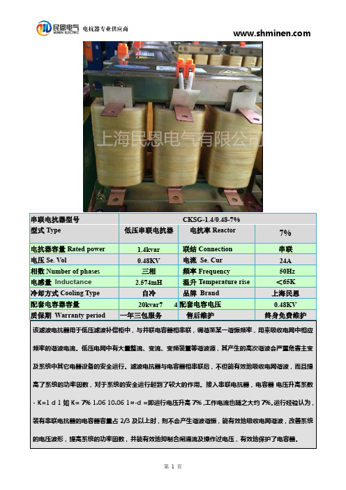
该滤波电抗器用于低压滤波补偿柜中,与并联电容器相串联,调谐至某一谐振频率,用来吸收电网中相应频率的谐波电流。
低压电网中有大量整流、变流、变频装置等谐波源,其产生的高次谐波会严重危害主变及系统中其它电器设备的安全运行。
滤波电抗器与电容器相串联后,不但能有效地吸收电网谐波,而且提高了系统的功率因数,对于系统的安全运行起到了较大的作用。
接入串联电抗器,电容器电压升高系数-K=1d 1如K=7%1.0610.061≈-d =即运行电压升高7%,工作电流也随之大约7%。
运行经验认为,装有串联电抗器的电容器容量占2/3及以上时,则不会产生谐波谐振,能有效地吸收电网谐波,改善系统的电压波形,提高系统的功率因数,并能有效地抑制合闸涌流及操作过电压,有效地保护了电容器。
串联电抗器型号CKSG-1.4/0.48-7%型式Type低压串联电抗器电抗率Reactor 7%电抗器容量Rated power 1.4kvar 联结Connection 串联电压Se.Vol0.48KV 电流Se.Cur 24A 相数Number of phases 三相频率Frequency 50Hz 电感量Inductance 2.574mH 温升Temperature rise <65K 冷却方式Cooling Type 自冷品牌Brand 上海民恩配套电容器容量20kvar74配套电容电压0.48KV 质保期Warranty period一年三包服务售后维护终身免费维护一.CKSG-1.4/0.48-7%串联电抗器型号含义(标示图)CK S G-1.4/0.48-7%额定电抗率7%(抑制5次7次谐波)系统额定电压0.48KV额定容量 1.4kvar干式铁芯自然冷却三相串联串联电抗器抑制5次7次谐波的民恩滤波补偿电抗器改如何选择呢?根据我公司多年为客户选配电抗器的经验得出以下结论;K值取4.5%~7%针对5次7次谐波抑制效果比较好,但是考虑到安全问题通常电抗率会选到7%或者7%。
固瑞克Reactor E-XP1电动聚脲设备
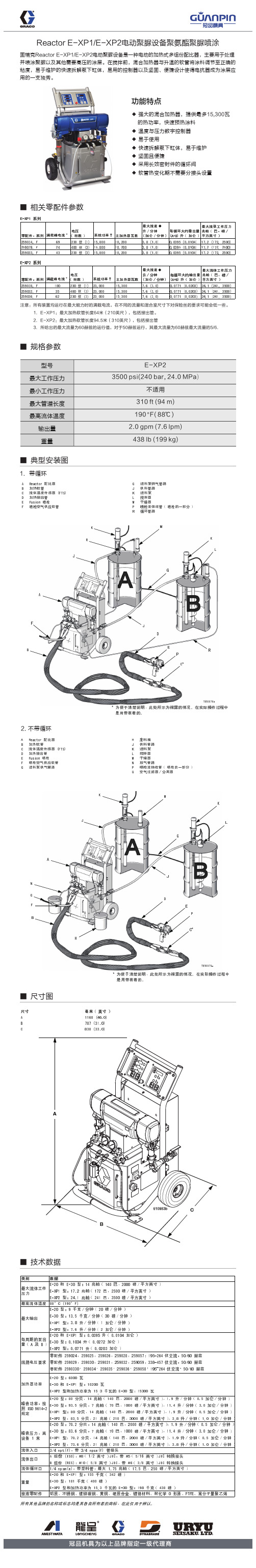
■ 规格参数
型号 最大工作压力 最小工作压力 最大管道长度 最高流体温度
输出量 重量
E-XP2 3500 psi(240 bar, 24.0 MPa)
不适用 310 ft (94 m) 190 °F( 88℃ ) 2.0 gpm (7.6 lpm) 438 lb (199 kg)
■ 典型安装图
1.带循环
功能特点
◆ 强大的混合加热器,提供最多15,300瓦 的热功率,快速预热涂料
◆ 温度与压力数字控制器 ◆ 易于使用 ◆ 快速拆解泵下缸体,易于维护 ◆ 坚固且便捷 ◆ 采用长效密封件的循环阀 ◆ 软管热变化期不需要分接头设置
■ 相关零配件参数
*
†
*
†
注意:所有装置均运行在最大能力时的满载电流,在不同的流量和混合室尺寸下对保险丝的要求可能会低一些。 1.E-XP1:最大加热软管长度64米(210英尺),包括接出管。 2.E-XP2:最大加热软管长度94.5米(310英尺),包括接出管 3.所给出的最大流量为60赫兹的运行值,对于50赫兹运行,其最大流量为60赫兹最大流量的5* *
■ 尺寸图
A
C B
■ 技术数据
Reactor E-XP1/E-XP2电动聚脲设备聚氨酯聚脲喷涂
固瑞克Reactor E-XP1/E-XP2电动聚脲设备是一种电动的加热式多组份配比器,主要用于处理 并喷涂聚脲以及其他需要高压的涂层。在搅拌前,混合加热器与升温的软管将涂料调节至正确的 粘度,易于维护的快速拆解泵下缸体,易用的控制器以及坚固、便捷设计使得电抗器成为涂层应 用的一支独秀。
Trench的电抗器产品介绍
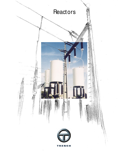
ReactorsIntroductionWith 40 years of successful field experience, Trench is the recognized world leader in the design and manufacture of air core, dry type, power reactors for all utility and industrial applications. The unique, custom design ap-proach, along with fully integrated engineering and manufacturing facilities in both North America and Europe have enabled Trench to become the technical leader for high voltage inductors worldwide.A deep commitment to the power industry, along with extensive investment in engineering, manufacturing and test capability give Trench customers the utmost in high quality, reliable products which are individually designed for each application. Trench reactor applications have grown from small, distribution class, current limiting reactors to complex EHV applied reactors surpassing 300 MVA per coil. Reactors are manufactured in accordance with ISO 9001 quality standard. Trench's highly develo-ped research and development program constantly addresses new technologies and their potential ap-plication in reactor products. Trench welcomes challenges for new applications for power reactors.This brochure outlines the features, capabilities and applications of Trench reactors.Although air-core, dry type reactors represent the majority of reactor production volume, Trenchalso produces a highly successful line of iron core/iron shielded and oil type reactors for specific appli-cation (eg. Resonance Grounding/ Petersen Coils). These reactors are also described in detail in other sections of the Trenchproduct catalogue.Design Features ofAir-Core Dry Type Reactors•Epoxy impregnated, fibreglass encapsulated construction•Aluminum construction through-out with all current carrying connections welded•Highest mechanical and short circuit strength•Essentially zero radial voltage stress, with uniformly graded axial voltage distribution between terminals•Low noise levels are maintained throughout the life of the reactor•Weatherproof construction, with minimum maintenance require-ments•Design service life in excess of 30 years•Designs available in compliance with ANSI/IEEE, IEC and othermajor standards.ReactorsFig. 1Three-phase stackedcurrent limiting reactor 2Series ReactorsReactors connected in series with the line or feeder. Typical uses are fault current reduction, load balancing in parallel circuits, limi-ting inrush currents of capacitor banks, etc.Reactor ApplicationsFig. 2Schematic diagramFig. 4Current limiting reactorFig. 3Single phase series reactors Trench reactors are utilized on transmission anddistribution systems. Although it is not possible to list all reactor applications, some of the most common are described below.Current Limiting Reactors,reduce the short circuit current to levels within the rating of theequipment on the load side of the reactor.Applications of current limiting reactors range from the simple distribution feeder reactor to large bus-tie and load balancing reactors on systems rated up to 765 kV/2100 kV BIL.Capacitor Reactors are designed to be installed in series with ashunt connected capacitor bank to limit inrush currents due toswitching, to limit outrush currents due to close in faults and to control the resonant frequency of the system due to the addition of the capacitor banks. Reactors can be installed on system voltages through 765 kV/2100 kV BIL. When specifying capacitor reactors,the requested continuous current rating should account for harmonic current content, tolerance on capacitors and allowable system overvoltage.3Buffer Reactors forElectric Arc Furnaces (EAF).The most effective use of EAFs is achieved by operating the furnace at low electrode current and long arc length. This requires the use of a series reactor in the supply system of the arc furnace transformer forstabilizing the arc.Fig. 5 Buffer reactor for E.A.F.Fig. 6Load flow control reactors Duplex Reactors are currentlimiting reactors which consist oftwo half coils, wound in opposition.These reactors provide a desirablelow reactance under normal con-ditions and a high reactance underfault conditions.Load Flow Control Reactors areseries connected on transmissionlines up to 800 kV.The reactors change the lineimpedance characteristic such thatload flow can be controlled, thusensuring maximum power transferover adjacent transmission lines.4Filter ReactorsFilter Reactors are used in conjunc-tion with capacitor banks to form series tuned harmonic filter circuits, or in conjunction with capacitor banks and resistors to form broad-band harmonic filter circuits.When specifying filter reactors, the magnitudes of fundamental and harmonic frequency current should be indicated. If inductance adjustment for fine tuning is required, the required tapping range and tolerances must be specified. Many filter applications require a Q-factor which is very much lower than the natural Q of the reactor. This is often achieved by connecting a resistor in the circuit.An economical alternative is the addition of a de Q'ing ring structure on a reactor. This can reduce the Q-factor of the reactor by as much as one tenth without the necessity of installing additional damping resistors. (see Fig. 9 below) These rings, mounted on the reactorare simply coupled to the magneticFig. 8Filter reactorsFig. 9Filter reactors withde Q’ing ringsFig. 7Schematic diagramFig. 10Capacitor/filter protection relayfield of the reactor. This eliminatesthe concern of space, connectionand reliability of additional compo-nents such as resistors.The Capacitor/Filter ProtectionRelay CPR 97is a microprocessorbased protection relay speciallydesigned for optimized protectionof shunt banks and harmonic filtercircuits.5Static VAR Compensators are used on transmission systems to improve the overall reliability, correct for voltage fluctuations and power factor as well asincreasing the transmission capability and reducing losses.Shunt ReactorsShunt Reactors are used to compensate for capacitive VARs generated by lightly loaded trans-mission lines or undergroundcables. They are normally connected to the transformer tertiary winding but can also be directly connected on systems up to 115 kV.Fig. 11Schematic diagramFig. 14Thyristor controlled reactorFig. 12Tertiary connected shunt reactorsFig. 13Thyristor controlled shunt reactors and filterreactors in a Static VAR CompensatorThyristor ControlledShunt Reactors are extensively used in static VAR systems, where reactive VARs are adjusted by thyristor circuits. Static VARcompensator reactor applications normally include:•Thyristor controlled shunt reactors (TCR). The compensating power is changed by controlling the current through the reactor by means of the thyristor valves.•Thyristor switched reactors (TSR)•Thyristor switched capacitor reactors (TSC)•Filter reactors (FR)6HVDC-ReactorsHVDC lines are used for longdistance bulk power transmissionFig. 15SchematicdiagramFig. 17HVDC-Smoothing reactorFig. 16AC-Filtersas well as back-to-back inter-connections between differenttransmission networks.HVDC Reactors normally includeSmooting Reactors, AC and DCHarmonic Filter Reactors as wellas AC and DC PLC Noise FilterReactors.7Smoothing ReactorsSmoothing reactors are used to reduce the magnitude of the ripple current in a DC system. They are used in power electronics applications such as variable speed drives and UPS systems. They are also required on HVDC transmission lines for system voltages up to 500 kV.Several design and construction techniques are offered by Trench.Fig. 18 Schematic diagramFig. 19Iron core, forced air cooled reactorFig. 20Air core,encapsulated winding designFig. 21Iron core,water cooled reactor8Test Lab ReactorsTest Lab Reactors are installed in high voltage and high power test laboratories. Some typical applications include current limiting, synthetic testing of circuit breakers, inductive energy storage, artificiallines, etc.Fig. 22Schematic diagramFig. 23Reactor bank for thevoltage circuit for synthetic testingof circuit breakers;32 kA peak to peak,0,318 mH to 353,6 mH,up to 1600 kV BILFig. 25Short circuittest reactorFig. 24Adjustablecurrent limiting reactor9Neutral Grounding ReactorsNeutral Grounding Reactors limit the line to ground fault current to specified levels. Specification should also include unbalanced condition continuous current andduration.Fig. 26Schematic diagramFig. 27Arc suppression coil 110 kV Fig. 28Standard arc suppression coilArc Suppression CoilsSingle-phase neutral grounding (earthing) reactors (arc suppression coils) are intended to compensate for the capacitive line-to-ground current during a single phase gro-und-fault.The arc suppression coil (ASC) represents the central element of the Trench earth fault protection system.Since the electric system is subject to changes, the inductance of the ASC used for neutral earthing must be variable.The earth fault detection system developed by Trench utilizes the plunger core coil (moveable core design). Based on extensive experi-ence in design, construction and application of ASCs, Trenchproducts can meet the most strin-gent requirements for earth fault compensating techniques.10A Trench air core dry type reactor consists of a number of parallel connected, individually insulated, aluminum (copper on request) conductors. These conductors can be small wire or proprietary cables custom designed and manufactured.The size and type of conductor used in each reactor is dependant on the reactor specification. The various styles and sizes of conductors available ensure optimum performance at the most economical cost. The windings are mechanically reinforced with epoxy resin impregnated fibreglass, which after a carefully defined oven cure cycle produces an encapsulated coil. A network of horizontal and vertical fibreglass ties coupled with the encapsulation minimizes vibration in the reactor and achieves the highest available mechanical strength.The windings are terminated at each end to a set of aluminum bars called a spider. This construction results in a very rigid unit capable of withstanding the stresses developed under the most severe short circuit conditions. Exceptionally high levels of terminal pull, tensile strength, wind loading and seismic withstand can be accommodated with the reactor. See Fig. 29 for details on construction.This unique design can be installed in all types of climates and environments and still offer optimum performance.Trench air core dry typereactors are installed in polluted and corrosive areas supplying trouble free operation. In addition to the standard fixed reactance type of coil, units can be supplied with taps for variable inductance.A number of methods are available to vary inductance for fine tuning or to provide a range of larger inductance steps.Trench utilizes various other designs for reactors (eg. iron core, water cooled, etc.) which are described in other sections of thiscatalogue.ConstructionFig. 29Typical Trench air core dry typereactor construction11It is the customer's responsibility to consider these minimum clearances, especially if steelreinforcing in concrete foundations or floors, or structural steel is involved in the building or station design. It is important, even outside these minimum magnetic clearan-ces, to avoid closed electrical loops with metallic parts.Terminals/Magnetic ClearanceIf required, non-magnetic extension brackets can be supplied by Trench to maintain thenecessary magnetic clearance below the reactor. Trench canprovide additional details on space requirements andrecommended reinforcing steel (rebar) design, if requested.Magnetic ClearanceMinimum clearances to metallic parts, and between coils, must be maintained as indicated by Figs. 32and 33. The values shown are only guidelines. Each specific reactor design will specify magnetic clearance requirements.Fig. 30Terminal orientation Fig. 31Terminal detailsMinimum magnetic clearance to other reactors and metallic partsnot forming closed loops (approximate values only)Terminals12Generally, air core, dry type reactors can be installed in either side by side or vertically stacked configurations and are often added to existing substations or locations where space limitations exist. With its highly developed computer design expertise, Trench can design reactors with optimized dimensions, to suit limited space requirements. The multi-spider construction allows flexibility in terminal location, which minimizes connection problems (see Fig. 35).Number of spider arms to be obtained from the actual quotation design.Installation assembly is minimal and typically requires only that brackets and insulators be bolted to the main coil. Installation instructions are provided with each reactor order.Trench takes intoconsideration all aspects of the reactor installation. These include requirements of ventilation, reactor supports, connections and busbar arrangements.Trench can also provide detailed information regarding:•magnetic field distribution analysis for mounting pads and foundations, grounding grids, fences and adjacent structures•Force calculations on adjacent coil installations, bus and cable connectionsInstallation•Seismic analysis on entire reactor assemblies, including support insulators and mounting pedestals, when furnished.Fig. 33Three-phasestacked arrangement13TestingAt Trench each reactor manufactured is subjected to a rigorous test and inspection program. In addition to the routine testing required by ANSI/IEEE or IEC a number of in-process tests are performed on each unit during production to ensure maximum in-service reliability. Each reactor is supplied with a certified test report with the results from all tests performed.In addition to routine testing we have the capability in our High Voltage and Power labs to perform most of the design tests described in the applicable standards. Design tests can be performed at an additional cost or test reports on similar units can be supplied upon request.The materials used in the manufacture of the reactor are also subject to a strict test program. Cooling duct spacers and the fibreglass epoxy resin composite encapsulation are subject to routine mechanical strength and tracking resistance testing. Accelerated thermal and multifactor aging studies are carried out which help to verify performance of the reactor components over their full service life.This testing coupled with our Quality Assurance program enables us to ensure the continuous perfor-mance of our reactors throughout the design service life.LossesThe custom design approach used by Trench allows optimum use of materials to control reactor losses. If a loss evaluation is not indicated in the specification, the reactor will be designed to meet the applicable standards at a most economical initial cost.All customers are aware of the advantages in minimizing system losses and are applying loss evaluation techniques to reactor purchases. In the cases where loss evaluations are included in the reactor specifications, Trench optimizes the initial cost of the reactor plus the cost of operating losses, to ensure the most economical balance. Generally, a loss optimized reactor will operate at a lower temperature rise and will thus extend the reactor overload capability.Trench's ability to design and manufacture low loss reactors al-lows many electric power utilities to economically justify the replacement of older, inefficient reactor installations. The low loss reactors can usually be installed on existing mounting pads.Losses can also be influenced for other purposes. In some applications it is important to control the Q factor (X/R ratio) of the reactor. This may be important at the fundamental frequency or at specific harmonic frequencies where additional losses are advantageous, for example capacitor switching reactors and certain filter applications.Testing/LossesFig. 34High voltage test laboratory 14Trench designs andmanufactures enclosures and support pedestals specifically for air core, dry type reactors.Enclosures, depending on the requirement, are made of steel or fibreglass and can be designed for indoor or outdoor installations.Trench enclosure design minimizes circulating current loops and opti-mizes the size by defining ventila-tion area and acceptable tempe-rature rise. Enclosures have been qualified as completeassemblies by short circuit testing of the enclosed reactor.Trench can supply support pede-stals to elevate reactor live parts to a height commensurate with per-sonnel safety standards. Pedestals also provide propermagnetic clearance below the reactor.Various pedestal designs are available and include fibreglass,braced aluminum and non-magnetic steel designs.Trench can recommend the most practical pedestal for each reactor application. Additional information on enclosures and pedestals is available on request.Sound shields can be provided to reduce the reactor noise level for special applications (HVDC).Enclosures and PedestalsFig. 35Filter reactor with sound shieldFig. 36Filter reactor with top-hatand pedestal15Data required with order•Reactor application•Indoor or outdoor installation•System voltage,impulse insulation level (BIL)•Rated and maximum continuous current (fundamental and harmonics)•Short circuit current level and duration•Rated inductance/impedance•Mounting arrangement (side by side or vertical stack)•Detailed accessory requirements (connectors, buswork, etc.)•Location of installation and site conditions•Ambient temperature range Trench Austria GmbH Paschinger Strasse 49, Postfach 13 A-4060 Linz-Leonding/Austria Phone+43.732.6793-0Fax+43.732.671341E-Mail sales@TrenchAustria.at Trench Brasil LTDAVia Expressa de Contagem, 2685 CEP 32370-485Contagem, MG - BrasilPhone 55. 31. 391-5959Fax 55. 31. 391-1828E-mailtrenchbrasil@ Trench LimitedCoil Product Division71 Maybrook Drive, Scarborough Ontario, Canada M1V 4B6 Phone (416) 298-8108Fax (416)298-2209E-Mail sales@ Trench LimitedInstrument Transformer Division 390 Midwest Road, Scarborough Ontario, Canada M1P 3B5Phone (416) 751-8570Fax (416)751-6952E-Mail sales@ Trench France S.A.16, rue du Général Cassagnou B.P. 70F-68302 St-Louis Cedex/France Phone +33.3.8970 23 23Fax +33.3.89 67 26 63E-Mail sales@ Trench Germany GmbHNürnberger Strasse 19996050 Bamberg/GermanyPhone +49.951.1803-0Fax +49.951.1803-224E-Mail sales@trench.deTrench Switzerland AG Lehenmattstrasse 353CH-4028 Basel/Switzerland Phone +41.61.315 5111Fax +41.61.315 59 00E-Mail sales@trench.chSubject to change without notice04.2000E 600。
CKSC串联电抗器

CKSC-15/10-5CKSC-15/10-5是上海昌日电子科技生产的CKSC系列高压串联电抗器,CKSC-15/10-5与并联电容器BFM-300-10-3(单相也能够,总容量300KVAR)相串联,具有补偿电网无功功率、提高功率因数、抑制谐波电流、限制合闸涌流等功能,CKSC-15/10-5高压串联电抗器适用于电力系统、电力化铁道、冶金、石化等较高防火要求、电磁干扰要求和安装空间有限的城网变电站、地下变电站和微机操纵变电站等场所CKSC-15/10-5型号代表意义5%10KV15KVAR三相串联电抗器CKSC-15/10-5 全称是10KV三相高压环氧浇铸电抗器电抗器容量是 15KVAR ,电抗率6%1,CKSC-15/10-5串联电抗器参数表2,CKSC-15/10-5串联电抗器性能与技术参数11 周围环境无有害气体,无易燃易爆物品,良好的通风。
3,CKSC-15/10-5电抗器外形示用意4,CKSC-15/10-5 串联电抗器结构特点1 CKSC-15/10-5 串联电抗器气隙不改变CKSC-15/10-5其铁芯材料采用的是优质的进口硅钢片,芯柱被多个气隙分成均匀的小段。
气隙的隔绝介质采用的是环氧布板,这样就能够保证气隙在长期运行中不发生变化。
2 CKSC-15/10-5串联电抗器铁芯的端面处理铁芯的端面采用了优质的硅钢片端面胶,它的粘合力非常强,能够使硅钢片紧紧地粘结一起,不仅有效地减小了运行时的噪音,并且防潮防尘性能也十分优异。
3 CKSC-15/10-5串联电抗器采用环氧浇注型好处高压串联电抗器的整个外形呈环氧浇注型,其内外线圈的敷设采用了环氧玻璃网格分布方法,并且是采用F级环氧浇注体系在真空状态下进行浇注,不仅具有强大的绝缘性能,而且还具有极高的机械强度,即使是受到大电流冲击也不会开裂,环氧浇注线圈具有防水、局部放电量低等优点,即使是在极其恶劣的环境条件下也能安全运行。
4 CKSC-15/10-5串联电抗器防震处理环氧浇注线圈的上下端都采用了环氧垫块和硅橡胶防震垫,能够有效减小线圈运行时的震动强度CKSC-15/10-5 三相高压环氧浇注电抗器实物图CKSC-15/10-5串联电抗器成效示用意CKSC-15/10-5电抗器在额定的负载下能够长期正常运行的时刻。
ABB变频器专用输出电抗器 现货供应
ABB变频器配套输出电抗器适当选配电抗器与变频器配套使用,可以有效地防止因操作交流进线开关而产生的过电压和浪涌电流对它的冲击,同时亦可以减少变频器产生的谐波对电网的污染,并可提高变频器的功率因数。
变频器用到的电抗器有3种:输入电抗器、输出电抗器、直流电抗器。
1、输入电抗器主要作用是抑制进线电源的网侧谐波,增大进线电源主回路的短路阻抗。
据此灵活考虑是否使用。
2、输出电抗器主要作用是平衡出线电缆的分布容性负载,增大出线主回路的短路阻抗。
并能抑制变频器输出的谐波,起到减小变频器噪声的作用。
两台以上变频器并联运行时,还起到限制换相环流和负荷平衡的作用。
前者考虑电缆的长度而确定是否使用,后者则必须使用。
3、直流电抗器主要用于公共直流母线型的交-直-交变频传动系统中。
如果公共整流器的电流数学模型为感性负载,则必须使用;如果是容性负载,则可以不用。
不管哪种情况,使用直流电抗器都能起到抑制直流电流波动的作用。
上海昌日电子科技有限公司专业生产变频器周边配套电抗器,输入电抗器(进线电抗器),输出电抗器(出线电抗器),直流电抗器(平波电抗器),公司依靠多年的市场反馈经验,可定做各类变频器配套的电抗器。
常规规格都有现货,批量生产,价格优惠。
ABB变频器输出电抗器概述变频器专用输出电抗器,是依靠线圈的感抗来阻碍电流变化的电器,抑制变频器产生的高次谐波,其通常串联于变频器出线端和负载之间,并因此而得名。
ABB变频器输出电抗器功能1、降低工频暂态过电压,这是利用变频器专用输出电抗器的空载或轻负荷线路上的电容效应来实现的;2、改善长输电线路上的电压分布;3、缓解变频器输出端的三相不平衡现象,减轻线路上的能量损失;使轻负荷时线路中的无功功率尽可能就地平衡,防止无功功率不合理流动;4、降低高压母线上工频稳态电压,便于发电机同期并列;5、防止发电机带长线路可能出现的自励磁谐振现象。
ABB变频器输出电抗器结构特点1、常见的变频器专用输出电抗器,一般都是铁芯干式;2、变频器专用输出电抗器的铁芯,采用优质低损耗进口冷轧硅钢片,气隙采用环氧层压玻璃布板作间隔,以保证变频器专用输出电抗器气隙在运行过程中不发生变化;3、变频器专用输出电抗器的线圈,采用H级漆包扁铜线绕制,排列紧密且均匀,外表不包绝缘层,且有极佳的美感且有较好的散热性能;4、变频器专用输出电抗器的芯柱部分紧固件,采用无磁性材料,减少运行时的涡流发热现象;5、变频器专用输出电抗器的外露部件,均采取了防腐蚀处理,引出端子采用镀锡铜管端子;6、变频器专用输出电抗器与国内同类产品相比具有体积小、重量轻、外观美等优点,可与国外知名品牌相媲美。
CKSG-3.5/0.45-7%
该滤波电抗器用于低压滤波补偿柜中,与并联电容器相串联,调谐至某一谐振频率,用来吸收电网中相应频率的谐波电流。
低压电网中有大量整流、变流、变频装置等谐波源,其产生的高次谐波会严重危害主变及系统中其它电器设备的安全运行。
滤波电抗器与电容器相串联后,不但能有效地吸收电网谐波,而且提高了系统的功率因数,对于系统的安全运行起到了较大的作用。
接入串联电抗器,电容器电压升高系数-K=1d 1如K=7%1.0610.061≈-d =即运行电压升高7%,工作电流也随之大约7%。
运行经验认为,装有串联电抗器的电容器容量占2/3及以上时,则不会产生谐波谐振,能有效地吸收电网谐波,改善系统的电压波形,提高系统的功率因数,并能有效地抑制合闸涌流及操作过电压,有效地保护了电容器。
串联电抗器型号CKSG-3.5/0.45-7%型式Type低压串联电抗器电抗率Reactor 7%电抗器容量Rated power 3.5kvar 联结Connection 串联电压Se.Vol0.45KV 电流Se.Cur 64.15A 相数Number of phases 三相频率Frequency 50Hz 电感量Inductance 0.902mH 温升Temperature rise <65K 冷却方式Cooling Type 自冷品牌Brand 上海民恩配套电容器容量50kvar 4配套电容电压0.45KV 质保期Warranty period一年三包服务售后维护终身免费维护一.CKSG-3.5/0.45-7%串联电抗器型号含义(标示图)CK S G-3.5/0.45-7%额定电抗率7%(抑制5次7次谐波)系统额定电压0.45KV额定容量 3.5kvar干式铁芯自然冷却三相串联串联电抗器抑制5次7次谐波的民恩滤波补偿电抗器改如何选择呢?根据我公司多年为客户选配电抗器的经验得出以下结论;K值取4.5%~7%针对5次7次谐波抑制效果比较好,但是考虑到安全问题通常电抗率会选到7%或者7%。
电抗器培训资料(入门必备)
电抗器培训培训人:高先生QQ:471810252培训内容一、电抗器介绍1.1电抗器分类及作用二、电抗器原理及特点2.1变频器用电抗器2.1.1工作原理2.1.2参数计算2.1.3选型2.2无功补偿用电抗器2.1.1工作原理2.1.2参数计算2.1.3选型三、电抗器工艺3.1主要材料及其特性3.1.1磁性材料3.1.2导体3.1.3绝缘材料3.1.4机械紧固件3.2工艺流程3.2.1卷曲3.2.2矽钢片堆叠3.2.3组立3.2.4浸漆3.2.5包装电抗器介绍1.1、电抗器分类及作用1.1.1分类电抗器:又叫电感器,即电感线圈,英文名reactor。
目前市场上运用广泛的主要有以下两类:变频器用电抗器和无功补偿用电抗器。
变频器用电抗器主要分为:输入电抗器(又叫进线电抗器)、输出电抗器(又叫出线电抗器)以及直流电抗器(又叫平波电抗器或者DC电抗器)。
无功补偿用电抗器主要分为:解谐电抗器(又叫消谐电抗器或者串联电抗器)和滤波电抗器!其他电抗器还有限流电抗器、阻尼电抗器等等。
名称运用场合作用输入电抗器变频器输入侧保护变频器,抑制电网中的谐波,防止因误操作造成的突波输出电抗器变频器输出侧减小dv/dt以及输电线的分布电容对负载的影响直流电抗器变频器整流输出侧与逆变输入侧之间改善电流波形,减小直流电路中的纹波,防止整流桥损坏解谐电抗器无功补偿系统中的电容器前段抑制电网中的谐波,保护电容器的正常运行滤波电抗器与电容器串联,并联再含有谐波的电网中消除电网中的某一次谐波,达到保护电网中设备的目的1.1.2运用场合及作用电抗器原理及特点2.1变频器用电抗器变频器用电抗器主要分为:输入电抗器(又叫进线电抗器)、输出电抗器(又叫出线电抗器)以及直流电抗器(又叫平波电抗器或者DC电抗器)。
2.1.1工作原理1.输入电抗器:当电网输入电压发生波动时,对电网中的波动部分进行限制,以磁转换的形式抑制波动的电压,从而达到稳定电网电压的目的!2.输出电抗器:变频器的SPWM脉冲波形电压通过输出电抗器时,电抗器能够有效的较低电压的变化率,使输出电压的波形更加平缓,也能够减小输电线上的分布电容对负载的影响,减小电机的涡流损耗!3.直流电抗器:主要用于直流电路中,与电容一起形成一个滤波回路,用于消除电网中的纹波,得到更好的直流电压的目的。
TCR+FC型SVC静止动态无功补偿装置简介
TCR+FC型SVC静止动态无功补偿装置简介随着国民经济的发展和现代化技术的进步,电力网负荷急剧增大,对电网无功功率的要求与日俱增。
特别是如轧机、电弧炉等冲击、非线性负荷的不断增加,加上电力电子技术的普遍应用,使得电力网发生了电压波形畸变、电压波动闪变和三相不平衡等,产生了电能质量降低、网络损耗增加等不良影响。
因此解决好电网的无功功率因数补偿和谐波滤波问题,对于提高电能质量、安全运行、降低损耗、节能、充分利用电气设备的出力等具有重要的意义。
1、谐波的危害:1.电能的生产,传输和利用效率降低,电器设备过热,产生附加的振动和噪声2.绝缘老化,寿命缩短3.设备故障,引起电力系统局部发生串联谐振或者并联谐振4.谐波发生放大,造成电容器过热,膨胀甚至产生破裂5.继电保护和自动化控制装置误动作,使电能计量失准,造成混乱6.对通信和电子设备产生干扰。
2、简介90年代以来,随着高压晶闸阀的制造技术日趋成熟,绝大部分用户采用TCR+FC型SVC这种动态无功补偿及滤波装置来改善电网电能的质量。
晶闸管控制电抗器型静止动态无功补偿装置是一种可以自动调节的无功功率补偿装置。
它具有3个主要功能:抑制电压波动,改善功率因数,吸收电网谐波。
TCR+FC型SVC全称如下:图1:TCR+FC型SVC主回路接线图无源单调谐滤器FC以其结构简单、成本低、运行维护方便等特点被广泛应用于负荷冲击不大的有污染的供电系统中,具有吸收电网谐波和补偿无功功率两个功能。
安装于母线或者设备侧,设备组合方便,性能稳定。
TCR(Thyristor Controlled Reactor)是晶闸管投切电抗器型静止无功补偿装置。
由于单独的TCR只能吸收感性的无功功率,因此往往与并联电容器配合使用。
并联电容器后,使得总的无功功率为TCR与并联电容器无功功率抵消后的净无功功率。
3、TCR型补偿装置工作原理TCR型动补装置的补偿原理见图2所示。
图中Q C为电容器功率,Q L为负载感性无功功率,Q LS为补偿器所提供的感性无功功率。
- 1、下载文档前请自行甄别文档内容的完整性,平台不提供额外的编辑、内容补充、找答案等附加服务。
- 2、"仅部分预览"的文档,不可在线预览部分如存在完整性等问题,可反馈申请退款(可完整预览的文档不适用该条件!)。
- 3、如文档侵犯您的权益,请联系客服反馈,我们会尽快为您处理(人工客服工作时间:9:00-18:30)。
哈尔滨电抗器-哈尔滨电抗器厂家直供上海昌日电子科技有限公司专业生产变频器周边配套元件输入电抗器,输出电抗器,直流电抗器,低压补偿柜串联电抗器,高压补偿柜CKSC高压串联电抗器。
公司常规产品都有现货,公司与各个专线物流签订协议,保证安全快捷到达您手中。
电抗器厂家直销价格优惠!输入电抗器输入电器器英文名称Input AC reactor 变频器的输入端安装JXL输入电抗器,一方面是为了减小谐波电流发射,另一方面可以提高变频器抗浪涌干扰的特性。
变频器的整流电路相当于一个谐波电压源。
我们知道,电压源当负载阻抗大时,输出电流会小。
因此,在变频器的电源输入端安装电抗器能够减小谐波电流的发射。
输出电抗器输出电抗器英文名称Output reactor ,当变频器输出到电机的电缆长度大于产品规定值时,应加输出电抗器来补偿电机长电缆运行时的耦合电容的充放电影响,避免变频器过流。
变频器输出端增加输出电抗器的作用是为了增加变频器到电动机的导线距离,输出电抗器可以有效抑制变频器的IGBT开关时产生的瞬间高电压,减少此电压对电缆绝缘和电机的不良影响。
直流电抗器直流电抗器英文名称 DC Reactors 直流电抗器接在变频系统的直流整流环节与逆变环节之间,主要用途是将叠加在直流电流上的交流分量限定在某一规定值,保持整流电流连续,减小电流脉冲值,使逆变环节运行更稳定及改善变频器的功率因数串联电抗器串联电抗器LV-Series Reactors 低压串联电抗器适用于无功补偿系统中的电容器前端,抑制电网中的谐波,保护电容器的正常使用CKSG串联电抗器并联在电网中,低频时呈现容性,主要起到无功补偿功能;高频时,电网呈现感性,从而抑制谐波起动保护电容器的作用。
高压串联电抗器高压串联电抗器HV-Series Reactors 与并联电容器相串联,具有补偿电网无功功率、提高功率因数、抑制谐波电流、限制合闸涌流等功能,高压串联电抗器适用于电力系统、电力化铁道、冶金、石化等较高防火要求、电磁干扰要求和安装空间有限的城网变电站、地下变电站和微机控制变电站等场所哈尔滨电抗器作用1-1,哈尔滨电抗器-输入电抗器(Input AC reactor)作用■减少对电网的低次谐波污染,提高功率因数■限制变流器换相时电网侧的压降■限制晶闸管导通时电流上升率di/dt和电压上升率du/dt■对并联变流器解耦,改善电源电压的波形■减少浪涌电流和电压对变流器的冲击,提高变频系统可靠性和使用寿命1-2哈尔滨电抗器-输出电抗器(Output reactor )作用1、降低工频暂态过电压,这是利用变频器专用出线电抗器的空载或轻负荷线路上的电容效应来实现的;2、改善长输电线路上的电压分布;3、缓解变频器输出端的三相不平衡现象,减轻线路上的能量损失;使轻负荷时线路中的无功功率尽可能就地平衡,防止无功功率不合理流动;4、降低高压母线上工频稳态电压,便于发电机同期并列;5、防止发电机带长线路可能出现的自励磁谐振现象。
1-3哈尔滨电抗器-直流电抗器-DC Reactors作用因为脉动的直流输出电压中所包含的谐波分量,在逆变时将产生不必要的损耗和发热,谐波中的负序分量则产生反向力矩,而且当晶闸管深控时,若脉动的直流输出电压的瞬时值低于电动机的反电势,将使电流不连续。
整流电路的脉波数总是有限的,且在输出的直流电压中总是有纹波的,这种纹波往往有害,需要由平波电抗器加以抑制,平波电抗器用于整流以后的直流回路中,经平波电抗器后输出的直流接近于理想直流。
1-4,哈尔滨电抗器-串联电抗器LV-Series Reactors作用接入串联电抗器,电容器电压升高系数- K=1 d 1如K= 6% 1.06 10.06 1≈-d =即运行电压升高6%,工作电流也随之大约6%。
运行经验认为,装有串联电抗器的电容器容量占2/3及以上时,则不会产生谐波谐振,能有效地吸收电网谐波,改善系统的电压波形,提高系统的功率因数,并能有效地抑制合闸涌流及操作过电压,有效地保护了电容器哈尔滨电抗器-各类电抗器型号叁,举例说明CKSG-1.5/0.48-6详细说明CK:代表系列型号,以它作为产品型号的开头是为了让客户更好的区电抗器功能,CK代表串联电抗器,BK并联电抗器QK 启动电抗器S:代表相数,这里的S表示三相电抗器,用于补偿柜共补。
,还有D 代表单相电抗器,用于补偿柜分补。
G: 代表冷却方式空气冷却C代表环氧浇筑系列1.5: 代表电抗器的容量,容量选择范围0.3-30KVAR,如果对电抗器容量不了解,可致电详询。
0.48:指的是电容器电压,这里的单位是KV,1KV以下的电压为低压,6:指的是电抗率,常用的电抗率有5%,6%,7%,12%,14%哈尔滨电抗器-昌日变频器电抗器型号(输入电抗器,输出电抗器)JXL-口A/口%电压降(V)额定电流(A)输入电抗器CXL-口A/口%电压降(V)额定电流(A)输出电抗器哈尔滨电抗器-串联电抗器型号意义CK S G-1.5 /0.48 -6电抗率电容电压(KV)电抗器容量1.5(KVAR)干式冷却方式S代表三相D代表单相串联电抗器(Reactor)哈尔滨电抗器-高压串联电抗器CKSC-48/10-6型号代表意义CK S C- 48/ 10-6额定电抗率系统额定电压10KV额定容量48KV AR环氧浇铸型三相串联电抗器哈尔滨电抗器-举例CKSC-48/10-6型号说明CK:代表系列型号,以它作为产品型号的开头是为了让客户更好的区分电抗器的功能,这里的CK代表串联电抗器,BK并联电抗器QK 启动电抗器LK滤波电抗器XK代表限流电抗器S:代表相数,这里的S表示三相电抗器,用于补偿柜共补。
,还有D代表单相电抗器,用于补偿柜分补。
C: 代表C代表环氧浇筑系列G代表干式绕制48: 代表电抗器的容量,容量选择范围3-400KVAR,如果对电抗器容量不了解,可致电详询。
10:指的是电容器电压,这里的单位是KV,电压等级分为3KV,6KV,10KV,12KV电抗器称高压电抗器,也有被称为高压串联电抗器。
6:指的是电抗率6%,常用的电抗率有5%,6%,7%,12%,14%哈尔滨电抗器-变频器输入电抗器性能与技术参数哈尔滨电抗器-变频器输入,输出电抗器性能特点:铁芯采用优质硅钢片,芯柱经多个气隙分成均匀小块,气隙采用高温高强度粘接胶将芯柱的每个小段与上、下铁轭紧密粘接起来,铁芯端面采用高品质防锈漆喷涂工艺,解决了电抗器铁芯表面生锈问题。
在运行中大大减小了噪音和振动。
电抗器均采用真空浸漆工艺,经高温热烘固化。
线圈有良好的绝缘性能,整体机械强度高,防潮性能好线圈采用F、H级绝缘系统,大大提高了长期运行的可靠性。
温升低,损耗小,成本低,综合利用率高。
体积小,重量轻,占用空间小,便于安装。
哈尔滨电抗器-变频器输入,输出电抗器技术参数1、额定工作电压:380V/50Hz或660V/50Hz2、额定工作电流:5A至1600A@40℃3、抗电强度:铁芯-绕组3500VAC/50Hz/10mA/10s无飞弧击穿4、绝缘电阻:1000VDC绝缘阻值≥100MV5、电抗器噪音:小于65dB6、防护等级:IP007、绝缘等级:F级以上8、产品执行标准:IEC289:1987电抗器GB10229-88电抗器(eqv IEC289:1987)JB9644-1999半导体电气传动用电抗器哈尔滨电抗器-串联电抗器性能参数1.串联电抗器可用于400V、660V系统。
2.串联电抗率的种类:1%、6%、7%,12%3.额定绝缘水平3kV/min。
4.CKSG电抗器各部位的温升限值:铁芯不超过85K,电圈温升不超过95K。
5.CKSG电抗器噪声不大于45dB6.电抗器能在工频加谐波电流不大于1.35倍额定电流下长期运行。
7.电抗值线性度:在1.8倍额定电流下的电抗值与额定电流下的电抗值之比不低于0.95。
8.三相电抗器的任意两相电抗值之差不大于±3%。
9.串联电抗器耐温等级H级(180℃)以上。
哈尔滨电抗器-串联电抗器结构特点1.该CKSG系列电抗器分为三相和单相两种,均为铁心干式。
2.哈尔滨电抗器-串联电抗器铁芯采用优质低损耗进口冷轧取向硅钢片,芯柱由多个气隙分成均匀小段,气隙用环氧层压玻璃布板作间隔,保证电抗气隙在运行过程中不发生变化。
3.哈尔滨电抗器-串联电抗器采用H级或C级漆包扁铜线绕制,排列紧密且均匀,外表不包绝缘层,具有极佳的美感且有较好的散热性能。
4.哈尔滨电抗器-串联电抗器的线圈和铁芯组装成一体后经过预烘→真空浸漆→热烘固化这一工艺流程,采用H级浸渍漆,使电抗器的线圈和铁芯牢固地结合在一起,不但大大减小了运行时的噪音,而且具有极高的耐热等级,可确保电抗器在高温下亦能安全地无噪音地运行。
5.哈尔滨电抗器-CKSG电抗器芯柱部分紧固件采用无磁性材料,确保电抗器具有较高的品质因数和较低的温升,确保具有较好的滤波效果。
6.CKSG串联电抗器外露部件均采取了防腐蚀处理,引出端子采用冷压铜管端子。
7.该CKSG电抗器与国内同类产品相比具有体积小、重量轻、外观美等优点,可与国外知名品牌相媲美。
哈尔滨电抗器-高压串联电抗器性能与技术参数电抗器执行标准:JB5346-1998 串联电抗器标准GB10229-88 电抗器JB3837-2010 型号编制依据JB9644-1999 半导体电气传动用电抗1 系统电压6kV、10kV、10.5kV、11kV。
2 电抗率选择1%、4.5%、5%、6%、7%、12%、14%3 绝缘等级F级4 实验耐压42000V5 电抗器噪音电抗器噪声:≤45dB6 过载能力≤1.35倍下连续运行7 三相不平衡度电抗器相与相之间不平横度不大于±3%,8 电感量误差控制在+3%以内9 海拔高度不超过2000米。
10 运行环境温度-25℃~+45℃,11 相对湿度相对湿度不超过90%。
12 周围环境无有害气体,无易燃易爆物品,良好的通风。
上海昌日我公司是专业生产电抗器的厂家,电抗器有变频器输入电抗器,输出电抗器,直流电抗器。
补偿柜CKSG串联电抗器,电容专用串联电抗器,高压串联电抗器,电抗器系列种类齐全,订做非标电抗器产品。
哈尔滨电抗器-高压串联电抗器结构特点1 哈尔滨电抗器-串联电抗器气隙不改变哈尔滨电抗器其铁芯材料采用的是优质的进口硅钢片,芯柱被多个气隙分成均匀的小段。
气隙的隔绝介质采用的是环氧布板,这样就能够保证气隙在长期运行中不发生变化。
2 哈尔滨电抗器串联电抗器铁芯的端面处理铁芯的端面采用了优质的硅钢片端面胶,它的粘合力非常强,能够使硅钢片紧紧地粘结一起,不仅有效地减小了运行时的噪音,并且防潮防尘性能也十分优异。
3 哈尔滨电抗器-串联电抗器采用环氧浇注型好处高压串联电抗器的整个外形呈环氧浇注型,其内外线圈的敷设采用了环氧玻璃网格分布方法,并且是采用F级环氧浇注体系在真空状态下进行浇注,不仅具有强大的绝缘性能,而且还具有极高的机械强度,即使是受到大电流冲击也不会开裂,环氧浇注线圈具有防水、局部放电量低等优点,即使是在极其恶劣的环境条件下也能安全运行。