智能计数器说明书
JDM15系列 预置数计数器 说明书

JDM15 系列预置数计数器█ 特点z 功能齐全的通用预置数计数器 z DIN 标准面板尺寸(72×72mm) z 0.4英尺LED 数字显示,字体大且清晰 z 最高计数速度达到1000次/秒 z 多种工作模式,停电记忆功能z DC12V,30mA 辅助电源输出,可方便与传感器连接z 可直接与光电开关,接近开关或接点信号等连接z 符合的标准:Q/WDH02-2003、GB14048.5-2001、IEC60947-5-1:1997█ 型号说明JDM15-4 4位数;加法计数器 JDM15 5位数;加法、减法计数器JDM15-T 6位数;加法计数器(廉价的精简功能计数器)█ 技术参数电源电压AC/DC 100~240V 或AC/DC 12~24V 开机复位(无停电保持时) 16.7mS (低速≤30次/秒 )面板按钮复位 0.5mS (高速≤1000次/秒) 外部端子复位最小信号脉宽(信号占空比为1:1时)复位方式自动复位0.3~3秒可调0~99999 ×1×10×100(JDM15)继电器输出 2组 3A AC220V(阻性) 0~9999(JDM15-4) 触点电寿命 ≥105次计数范围0~999999 (JDM15-T)晶体管输出 开集电极100mA 30V(max) 计数信号输入辅助电源输出DC12V 30mA(max)可供传感器使用 1.触点信号 继电器,行程开关等 安装方式 面板式 2.无触点信号光电开关接近开关等开孔尺寸 68×68mm CP1: H →L 时计数(低电平计数)重 量 约0.35Kg CP2: L →H 时计数(高电平计数) 功 耗 ≤4VA信 号L = 0~2V H = 4~30V工作温度 -5~+40℃(但不结冰) 信号输入阻抗 ≥4.7K Ω 储存温度 -25~+55℃(但不结冰) 停电记忆≥10年湿度范围35~85%RH█ 电气特点绝缘阻抗 100 M Ω(DC500V ) 耐 压 AC2000V 50/60Hz 1分钟 抗 干 扰 IEC61000-4标准,等级3振 动抗振动:10-55Hz( 周期1分钟)振幅0.75mm, X Y Z 各方向1小时 误动作:10-55Hz 周期1分钟振幅0.5mm, X Y Z 各方向10分钟 冲 击抗冲击:30G X ,Y, Z 各3次 误动作:10G X ,Y ,Z 各3次JDM15 系列█外形尺寸JDM15-4注:JDM15、JDM15-T外型和JDM15-4一致,显示分别为5位和4位█工作程序图(JDM15-T只有N功能)N制式 K2-OFF K3-ON(到达设定值,停止计数)F制式 K2-OFF K3-OFF(到达设定值,可继续计数)R制式 K2-ON K3-OFF(到达设定值,自动复位)█接线图及说明CP1信号输入:(低电平有效)CP1 CP2不得同时输入信号JDM15、JDM15-4接线图CP2信号输入:(高电平有效)CP1 CP2不得同时输入信号复位信号输入:(低电平有效)JDM15-T接线图1.先预置好所需的功能和数值后使用,在运行中改变设定值无效,必须重新上电或复位才能有效。
爱控Love Controls LCT216计时器 计数器 速度计器说明书

LCT216 Timer/Counter/TachometerInstruction SheetThank you very much for purchasing Love Controls LCT216 series. Please read this instruction sheet before using your LCT216 series to ensure proper operation, and please keep this instruction sheet handy for your quick reference. For more detailed information, go to .DANGER! Caution! Electric Shock!WARNING!in counting or timing applications. If it will cause series injury to workers or damages on other equipment when used in a dangerous environment, please make sure it is installed in an automatic safety protection device.1Precaution !1.Always use recommended solder-less terminals: Fork terminal with isolation (M3 screw, width 7.0mm), hole (diameter 3.2mm). Screw size: M3x6.5 (with 6.8x6.8 square washer). Recommended tightening torque: 0.4 N.m (4kgf.cm). Applicable wire: solid/twisted wire of 2mm 2, 12AWG to 24 AWG. Please be sure to tighten them properly.2. Prevent dust or metallic debris from falling into the device and cause malfunctions.3. DO NOT modify or uninstall the device.4. DO NOT use empty terminals.5. Make sure the wires are correctly connected to proper terminals.6. Keep away from high-voltage and high-frequency environment during installation in case of interference.7. Prevent using the device in premises which contain:Dust or corrosive gas High humidity High radiation Vibration and shock8. LCT216 is an open-type device. Make sure to install it in an enclosure to prevent dust, humidity in case of anelectric shock.9. Please make sure the power cables and signal device are installed correctly before switching on the power;otherwise serious damage may occur.10. DO NOT touch the terminals or repair the device when the power is on; otherwise an electric shock may occur. 11. Please wait for one minute after the power is switched off to allow the capacitor to discharge and DO NOT touchthe internal wiring within this period.12. Use dry cloth to clean the device. DO NOT use acid or alkaline liquid to clean the device.2!LCD Display & IndicatorsRST 1/2 Light on when reset signal is detected BATCH "Batch Counting Mode” in Counter and Tachometer function K/P 1/2 Light on when key-protected mode is enabledSET 1 2 SV1, SV2 displayOUT 1/2 Light on when output is executing TAC Light on when Tachometer function is executingH M S Hour, minute, second, unit of timer, displayed in Timer functionCNT Light on when Counter function is executing TOTAL“Total Counting Mode” in Counter and Tachometer functionTMRLight on when Timer function is executingKey Operation"LOCK” again to enter Lock 1. In Lock 1, press “LOCK” once again to enter Lock 2. Press(Lock 1) disables the functions of all keys. (Lock 2) allows the user to change SV, and the functions of “RESET” remain. “LOCK” only functions in the non-key-protection status. Operation Mode & Configuration ModeOperationWhen the power is on, LCT216 will be in the operation mode. Pressto change SV, orto make changes on a desired digit. The indicator of the selected digit will flash. After the change is mode, press to save the setting. If SV or parameters are not changed, pressonce again to switch between SET1 and SET2.ConfigurationPressin the operation mode for more than 3 seconds to enter the configuration mode. Press again to switch among parameters. To return to the operation mode, press for more than 3 seconds.3Specifications !Power input AC 100 ~ 240V, 50/60Hz Input voltage range 85% to 110%, rated voltage Power consumption Less than 10VA External power supply 12VDC ±10%, 100mADisplay Double-line, 6-digit negative transmissive LCD displayNon-voltage input (NPN): ON impedance 1k Ω. ON residual voltage: 2V max. Input signalVoltage input (PNP): High level: 4.5 ~ 30VDC, Low level: 0 ~ 2VDC Relay: SPST max. 250VAC, 5A (resistance load)Output 1Transistor: NPN open collector. When 100mA /30VDC, residual voltage = 1.5VDC max.Relay: SPDT max.250VAC, 5A (resistance load)Output 2Transistor: NPN open collector. When 100mA /30VDC, residual voltage = 1.5VDC max.Dielectric strength 2,000VAC 50/60 Hz for 1 minuteVibration resistance Without damage: 10 ~ 55Hz, Amplitude = 0.75mm, 3 axes for 2 hours Shock resistance Without damage: drop 4 times, 300m/s 2, 3 edges, 6 surfaces and 1 corner Ambient temperature 0o C ~ +50o C Storage temperature -20o C ~ +65o C Altitude2,000m or lessAmbient humidity 35% ~ 85% RH (non-condensing) Pollution degreeDegree 24!Timerdown)CounterSelect inputReset min.Save data or powerSet up theSet up the TachometerSet up the average Reset min. pulse width Select input type (PNP Set up the delay time Timer + Counteroutput)5Timer Function !There are counting up/down modes, several counting units and output modes to choose from in the timer function.6Counter Function !Counter functions include: 1-stage counting, 2-stage counting, batch counting, total counting and dual counting.Output modes of counter The output of SV can be 1-stage or 2-stage. When the output is set to 1-stage, Output 2 will be the same as the Output 1.The output modes include: F, N, C, R, K, P , Q, A, S, T, DF When PV reaches SV, output is enabled but counting continues. Recounting starts after reset signal is over. Output 2 remains.N When PV reaches SV, output is enabled but counting stops. Recounting starts after reset signal is over. Output 2 remains.C When PV reaches SV, recounting executes automatically. Output 2 is pulse output. Output 1 remains till Output 2 is over.R When PV reaches SV, counting stops till Output 2 (pulse) is over for recounting. Output 1 remains till Output 2 is over.K When PV reaches SV, output is enabled but counting continues. Recounting starts after reset signal is over.P When PV reaches SV, output is enabled and recounting is automatically executed. But display of counting remains till Output 2 (pulse) is over.Q When PV reaches SV, output is enabled but the counting continues. Recounting starts after Output 2 (pulse) is over.A When PV reaches SV, output is enabled but the counting stops. Recounting starts and Output 2 (pulse) executes after reset signal is over.S When PV ≥ SV1, Output 1 is enabled. When PV ≥ SV2, Output 2 is enabled T When PV ≤ SV1, Output 1 is enabled. When PV ≥ SV2, Output 2 is enabled.DWhen SV=PV, output is enabled but counting continues. Addition and subtraction modes are valid.The time of Output 1 and Output 2 (pulse) can be set up separately, ranging from 0.01 to 99.99 seconds. Recounting refers to counting up or addition/subtraction counting starting from 0 and counting down starting from SV. The counting range: -99,999 ~ 999,999. The counting will restart from 0 if the counting exceeds the range.Save the data before power offis set, the current PV will be saved. WhenisWhen conducting unit conversion, PV = PV x PreScale value, ranging from 0.001 to 99.999.7Tachometer Function !Measuring Rotation speed: Measuring pulse width and determining current frequency Output methods: Lo-Lo, Lo-Hi, Hi-Lo, Hi-HiMeasurement value OUT1 set value : OUT1 ON Measurement value OUT2 set value : OUT2 ONMeasurement value OUT1 set value : OUT1 ON Measurement value OUT2 set value : OUT2 ONMeasurement value OUT1 set value : OUT1 ON Measurement value OUT2 set value : OUT2 ONthe power is switched on. (Range of delay time: 0.1 ~ 99.9 seconds.)average of 2n input data for more stable output value.8 Timer + Counter Function !In Timer + Counter function, SV1, PV1 and Output 1 are for Timer; SV2, PV2 and Output2 are for Counter. DIP switch is disabled. All timer and counter functions remain exceptRCY2, SCON, STON, STOFF in output mode of Timer functionCommand up/down, Individual up/down, quadrature counting in input mode, S, T, D in output mode of Counter function Only 1-stage counting in Counter function is available.9 Setting up Easy DIP Switch !The user can use DIP switch to set up parameters. When DIP is switched to ON, the corresponding parameters can only be read, not changed. SW Counter Timer Tachometer8Reset pulse width ON: 1ms, OFF: 20ms Reset pulse width ON: 1ms, OFF: 20ms Reset pulse width ON: 1ms, OFF: 20ms 7Input type ON: PNP OFF: NPN Unit of Timer (See Table 1) Input type ON: PNP OFF: NPN6 N/AUnit of Timer(See Table 1)N/A 5Counting speed ON: 10k CPS OFF: 30 CPS Unit of Timer (See Table 1) Counting speed ON: 10kHz OFF: 30Hz 4Output mode of counter (See Table 2) Output mode of Timer (See Table 2) Output mode of Tachometer (See Table 2) 3Output mode of counter (See Table 2) Output mode of Timer (See Table 2) Output mode of Tachometer (See Table 2) 2Input mode of counter ON: counting down OFF: counting up Time counting up/downON: down OFF: up N/A 1ON: Enable DIP OFF: Disable DIP ON: Enable DIP OFF: Disable DIP ON: Enable DIP OFF: Disable DIPSW5 SW6 SW7 Displayed unit OFF OFF OFF 0.01 sec ON OFF OFF 0.1 secTable 1OFF ON OFF 1 sec Output Mode ConfigurationON ON OFF min, 0.01 sec SW3 SW4Counter Timer Tachometer OFF OFF ON min, 0.1 sec OFF OFF F Signal ON Delay 1 Lo-Lo ON OFF ON 0.1 min ON OFF N Signal ON Delay 2 Lo-Hi OFF ON ON Min OFF ON C Signal OFF Delay Hi-Lo ON ON ON hr, min, sec ON ON R Signal ON Hi-Hi10Terminal Definition !Multi-Function Input PIN CounterTimerTachometerTimer + Counter CP1 CP1 CP1 CP2 Gate Gate Reset1 Reset1 Reset1 Reset1 Reset2 StartStart11Dimension & Panel Cutout !12How to Mount !1. Insert the controller through the panel cutout.2. Insert the mounting bracket into the mounting grooveat the top and bottom of the controller and push the mounting bracket forward until the bracket stops at the panel wall. 3. Insert and tighten the screws on the bracket to securethe controller in place.Table 2。
JDM3 电子式计数器 说明书

C
4 接线图
JDM3(无电压输入)
输入 复位
1
3
2
4
2 与 4 已在内部连接
输入 复位
1
3
0V
2
4
0V
2 与 4 已在内部连接
JDM3(直流电压输入)
输入 复位
+V
1K
1K
+V
1
3ห้องสมุดไป่ตู้
0V
2
4
0V
2 与 4 已在内部连接
输入 复位
+V
1
3
+V
0V
2
4
0V
2 与 4 已在内部连接
JDM3(交流电压输入)
+ AC/DC
3 主要参数及技术性能
电源 电池寿命 显示方式 输出方式 计数位数 计数速度 计数方式
无电压输入
直流电压输入 交流电压输入 复位方式 复位最小脉宽 计数误差 环境温度 安装方式 外形尺寸 开孔尺寸
内部电源 约6年(25℃) LCD显示,消“0”型(显“0”型可定做) 无输出 6位计数器或8位计数器 10次/秒或200次/秒 加计数 接点接通最大电阻:≤10kΩ(计数ON) 接点断开最小电阻:≥500kΩ(计数OFF) 输入最大残余电压:0.5V L:DC0V-2V H:4V-30V(H有效) (输入阻抗:≥4.7kΩ) AC/DC 24V~240V 面板按钮复位(6位),外部端子复位(6位、8位) ≥0.2s ≤±1次 -5℃~+40℃ 面板式 W48×H24×L52.9mm W45×H22.5mm
JDM3 电子式计数器
继电器类
1 适用范围
JDM3超小型电子式计数器内部自带锂电池供电,外型小巧,适用于各种线路中作计数用。
HIAC 8000A颗粒度计数器操作中文说明书

HIAC 8000A颗粒度计数器操作中文说明书目录一、8000A颗粒度计数器简介二、8000A颗粒度计数器控制、显示说明三、8000A颗粒度计数器操作说明四、8000A颗粒度计数器错误显示说明五、8000A颗粒度计数器功能菜单说明一、8000A颗粒度计数器简介HIAC颗粒度计数器系统由8000A或8000S计数器,空气或液态中传感器以及取样器(在液态情况)组成,如果使用8000S计数器,系统中必须同时有一台8000A和它的控制工作软件,8000A和8000S本身都包含脉冲检测电路,直流电源,微电脑和其他电子部件。
但8000A提供操作者的输入/输出界面。
在液态系统中的取样器用以输送适量体积和适当流速的含颗粒液态通过传感器的颗粒检测区。
在测空气的系统中不需要独立的取样器。
传感器检测出空气或液态介质中存在的固体颗粒,并转换为电压脉冲,电压脉冲的高度正比于颗粒的大小。
这些电压脉冲送入计数器中的八通道计数电路,每个通道计数测量在一规定范围中的脉冲。
通道1---通道8范围是相连续的。
颗粒脉冲的幅度超过通道的门限值,这脉冲即触发该通道一个计数。
在测试结束后,每个通道的计数以差分或累加形式显示,并可通过打印机打印。
8000A计数器对传感器,取样器和8000S进行控制。
数字串行通讯电路提供计算机远距离控制仪器的功能.计数器的“HOST”接口支持HIAC/ROYCO的DataLync和DataLoop选件,在连接口包含+13V的电源,提供远距离操作.二、8000A颗粒度计数器控制、显示说明1.控制/显示8000A的全部控制和显示,由键盘和显示器两者相互结合实现.8000S需完全依靠8000A控制和显示它的工作,图3-l是8000A键盘和显示.一旦系统安装好,激发这两部件成为用户的主要工作。
图1-1 Model 8000A - KeVfjad/Displa\/1.1显示8000A输出显示屏是40列16行液晶显示器(LCD).其中5行在所有屏幕中都用于规定的功能.(见图1-2)图1-2第1行通常显示HIAC/ROYCO的标记,日期和时间.当取样时,HIAC/ROYCO标记将被测量经历的时间取代。
美高加索 Gemini 1000 2000 计数器 计时器说明书
!SEALED FRONT PANEL CONSTRUCTION (NEMA 4/IP65)!NON-VOLATILE MEMORY (E 2PROM)!ABILITY TO LOCK OUT FRONT PANEL FUNCTIONS !SIMPLIFIED FRONT PANEL FOR PROGRAMMING EASE !6-DIGIT, 0.56" (14.2 mm) HIGH LED DISPLAY WITH NEGATIVESIGN & OVERFLOW INDICATORS!FUNCTIONS AS COUNTER OR RATE INDICATOR!INPUT SCALING FOR BUILT-IN RATE MULT./DIV.!ACCEPTS INPUT COUNT RATES UP TO 10 KHz!BI-DIRECTIONAL COUNTING, UP/DOWN CONTROL!QUADRATURE SENSING (Up to 4 times resolution)!ANTI-COINCIDENCE ADDITION AND SUBTRACTION!SEPARATE INPUT FOR MAGNETIC PICKUPS!SOLID-STATE CURRENT SINK OUTPUT(S)!OPTIONAL RELAY OUTPUTS (Field Replaceable)!PROGRAMMABLE OUTPUT TIME DELAYS!UP TO THREE RIGHT-HAND “DUMMY ZEROS”!FULL PROGRAMMABILITY OF DECIMAL POINT LOCATION ANDLEADING ZERO BLANKING DESCRIPTION The Gemini 1000 and 2000 offer the features and performance of asingle/dual level preset counter or a programmable sample time rate indicator inone economically priced package. The reliability of solid-state MOS technologycoupled with the flexibility of user programmable functions makes these unitsideally suited to handle practically any preset control application.As a counter, the Gemini 1000/2000 offers a choice of six (6)programmablecounting modes to cover Bi-directional, Anti-Coincidence, and Quadratureapplications. The input circuitry is switch selectable to accept signals from awide variety of sources. In addition, the unit may be programmed to registercounts on both edges of the input signal thus providing frequency doublingcapability. The choice of several reset cycle modes along with the compatibilityof count and control inputs to other RLC products, provides added versatility forboth stand-alone and systems counter needs.As a rate indicator, the Gemini 1000/2000 features crystal-controlledaccuracy along with a variety of data sampling times to allow the neededresolution for precision applications. The combination of 5-digit scale factorand decade scale multipliers provide a wide range of scaling correction fordirect readout in terms of units being measured.The Gemini 2000 20 mA Current Loop Option provides the capability oftwo-way communications between the Gemini 2000 and a variety ofequipment, such as a printer, remote terminal, or host computer. The Baud ratecan be set to 300, 600, 1200 or 2400 baud. The format for transmitted andreceived data is 1 start bit, 7 data bits, 1 parity bit (odd), and 1 stop bit. Whenutilizing an external power supply (30 VDC max), up to 16 units can beinstalled in the loop, each with an individual address. When utilizing theGemini’s 20 mA current source, up to seven units can be installed in a loop.The Count value, Scale Factor, and Preset values can be interrogated. TheScale factor and Presets can be changed by sending the proper command codesand numerical Data. Other functions such as resetting the count, and a combined transmit count and reset can also be performed. Various “Print Options”can be selected to automatically interrogate the Count Value, Preset,or Scale Factor by activating the “Print Request”terminal when a printer is being used, or by sending a “transmit per Print Options”(P)command. All command codes and numerical data are sent in ASCII.The construction of the Gemini 1000/2000 features a zinc die-cast bezel offering maximum durability with a high quality appearance. The sealed front panel meets NEMA 4/IP65 specifications, for wash-down and/or dust when properly installed. Electrical connections are made via pluggable terminal strips at the rear of the unit. Clamp-type pressure plate terminals accept stripped #14AWG wire without lugs.SPECIFICATIONS1. DISPLAY:6-digit 0.56" (14.2 mm) High LED display.2. POWER REQUIREMENTS:AC Power:Switch selectable 115/230 V AC (±10%), 50/60 Hz, 20 V A DC Power:*****************.3. SENSOR POWER:+12 VDC (±25%) @ 100 mA max.4. MEMORY:Non-volatile E 2PROM memory retains all programming information and count value when power is removed or interrupted.5.INPUTS A &B:Switch selectable to accept count pulses from a variety of sources including switch contacts, outputs from CMOS or TTL circuits, and all standard RLC sensors.Current Sourcing - Unit provides 3.9 K Ωpull-down load for sensors with current sourcing outputs. Max. input voltage = 28 VDC @ 7 mA.Current Sinking - Unit provides 7.8 K Ωpull-up load for sensors with current sinking outputs. Max. sensor current = 1.6 mA.Debounce - Damping capacitor provided for switch contact debounce.Limits count speed to 100 Hz max. with 50% duty cycle.GEMINI 1000/2000 - 6-DIGIT PRESETTABLE COUNTERS OR RATE INDICATORSGEMINI 1000 - SINGLE LEVEL & GEMINI 2000 - DUAL LEVEL w/OPTIONAL 20 mA CURRENT LOOPPROGRAMMABLE FUNCTIONSUNIT PERSONALITYFunctions as a Counter and Rate Indicator.PRESET(S)Range 0 to ±999999SCALE FACTORS5-digit input scaling, Range 0.0000 to ±5.9999.SCALE MULTIPLIERMultiplies the contents of the 9-digit internal counter by a factor of 1, 0.1, 0.01, or 0.001 to view the desired number of significant digits on the 6-digit display. COUNTING MODESCount with InhibitCount with Up/Down Control2-Input Anti-Coincidence Add2-Input Anti-Coincidence Add/SubtractQuadratureQuadrature X4RESET ACTIONReset-to-Zero:Output activates when count equals the preset value. Counter returns to zero when reset.Reset-to-Preset:Output activates when count equals zero. Counter returns to preset value when reset.RESET MODESManual ResetAutomatic Reset at PresetAutomatic Reset after Output Time DelayNote: Manual reset via front panel pushbutton or remote “RST.” terminal can be programmed for momentary or maintained action. Front panel reset may be disabled by a switch at the rear of the unit.SELF-TESTPerforms a complete check on the display and output circuitry along with a functional check on the CPU. Self-test is non-destructive and may be performed during a process without losing counts.FREQUENCY DOUBLINGRegisters counts on both edges of input signal.DECIMAL POINT & LEADING ZERO BLANKINGDecimal point programmable to desired location. Leading zero blanking, when selected, begins with second digit to the left of the decimal point. RIGHT-HAND DUMMY ZEROSUp to three non-functional zeros may be placed on the least significant end of the display.OUTPUT TERMINATION MODESTerminate at “other” Output Start (Gemini 2000 only)Terminate at “other” Output End (Gemini 2000 only)Terminate at Manual ResetTerminate at Manual Reset EndTerminate after Time DelayBoundaryFor positive preset value: Output terminates when Display is less than Preset.For negative preset value: Output terminates when Display is greater than Preset (i.e. more positive).Note: In any of the above modes, the unit may be programmed for “Reverse Phase” operation which complements the logic state of the output. OUTPUT TIME DELAYProgrammable from 0.01 to 599.99 seconds. Accurate to ±(0.01% + 10 msec.). SAMPLE TIME MULTIPLIERMultiplies the basic one-second data sampling time by 1, 2, 5, 10,20, or 50. Accurate to ±0.01%.FRONT PANEL LOCKOUT MODESWhen the “Program Disable” control input is activated, the ability to change front panel programmed functions will be prevented as per the following modes: Complete Front Panel DisablePreset(s)Enabled OnlyScale Factor Enabled OnlyBoth Preset(s)and Scale Factor EnabledNote: Reset may be enabled or disabled in any of the above modes.SPECIFICATIONS (Cont’d)Lo Bias- Input trigger levels V IL= 1.5 V max., V IH= 3.75 V.Hi Bias- Input trigger levels V IL= 5.5 V max., V IH= 7.5 V.Note: Bias levels given are ±10% @ 12 VDC. They vary proportionally with sensor supply voltage.6. MAGNETIC PICKUP INPUT:Sensitivity- 150 mV peak nominalHysteresis - 100 mV nominalInput Impedance- 26.5 KΩ@ 60 Hz nominalMaximum Input Voltage- ±50 V peak7. MAXIMUM COUNT RATES:Uni- or Bi-Directional Modes:9 KHz; 8 KHz (X2)2-Input Anti-Coincidence Modes:5 KHz; 4 KHz (X2)Quadrature Modes:5 KHz; 4 KHz (X2 or X4)Rate Indicator:10 KHz; 8 KHz (X2)8.CONTROL INPUTS:Reset- Active Low (V IL= 1.5 V max.) internally pulled up to +12 VDC(I SNK= 3 mA), response time = 10 msec (typical).Program Disable- Active Low (V IL= 1.5 V max.), internally pulled up to +5 VDC (I SNK= 1 mA).Print Request- (GEM2 only)Active Low (V IL= 1.5 V max.) internally pulled up to +5 VDC (I SNK= 1 mA).9. SERIAL COMMUNICATIONS (Optional, Gemini 2000 only):Type- Bi-directional 20 mA current loop, 20 mA source provided. (Powers up to seven units in a loop with internal current source.) Baud Rate- Programmable 300 to 2400.Maximum Address- 16 units (0 to 15). (Actual number in a single loop is limited by serial hardware specifications.)Data Format- 10 bit frame, Odd parity (one start bit, 7 data bits, one odd parity bit, and one stop bit.)Serial Hardware Specifications-SO- Output Transistor Rating: V MAX= 30 VDC, V SA T= 1 V MAX@ 20 mA. (Can address 16 units in a loop)SI- Input Diode Rating: V F= 1.25 V TYP; 1.5 V MAXNote: The compliance voltage rating of the source must be greater than the sum of the voltage drops around the loop.10. OUTPUT(S):Solid-State- Current sinking NPN Open Collector Transistor(s). I SNK= 100 mA max. V OH= 30 VDC max. (Internal Zener Diode Protected). V OL=1 VDC max @ 100 mARelay(s)- Mounted on a field-replaceable P.C. board. Form C contacts rated5 amps @ 120/240 V AC, 28 VDC (resistive load), 1/8 H.P. @ 120 V AC(inductive load). The operate time is 5 msec nominal and the release time is 3 msec nominal.Relay Life Expectancy- 100,000 cycles at max. rating. (As load level decreases, life expectancy increases.)Programmable Timed Outputs(s)- The timed output(s)can be set from0.01 to 599.99 seconds, ±(0.01% + 10 msec).11.CERTIFICATIONS AND COMPLIANCES:SAFETYIEC 1010-1, EN 61010-1: Safety requirements for electrical equipment for measurement, control, and laboratory use, Part 1.IP65 Enclosure rating (Face only), IEC 529Type 4 Enclosure rating (Face only), UL50ELECTROMAGNETIC COMPATIBILITY:Notes:1. Metal bezel of unit connected with ground lead from rear bezel screw tometal mounting panel.2. When the unit is DC powered, a power line filter (RLC# LFIL0000 orequivalent) was installed, so as not to impair the function of the unit.Refer to the EMC Installation Guidelines section of the manual for additional information.Immunity to EN 50082-2Electrostatic discharge EN 61000-4-2Level 2; 4 Kv contact 1Level 3; 8 Kv air Electromagnetic RF fields EN 61000-4-3Level 3; 10 V/m80 MHz - 1 GHzFast transients (burst)EN 61000-4-4Level 4; 2 Kv I/O2 Kv power 2RF conducted interference EN 61000-4-6Level 3; 10 V/rms150 KHz - 80 MHzEN 61000-4-8Level 4; 30 A/m Emissions to EN 50081-2RF interference EN 55011Enclosure class APower mains class A Power frequency magnetic fields12. ENVIRONMENTAL CONDITIONS :Operating Temperature : 0 to 50°CStorage Temperature : -40 to 80°COperating and Storage Humidity : 85% max. relative humidity (non-condensing) from 0 to 50°C.Altitude : Up to 2000 meters13. CONSTRUCTION :Metal die-cast bezel, plastic case. This unit is rated for NEMA 4/IP65 indooruse. Installation Category II, Pollution Degree 214. WEIGHT : 2.1 lbs. (0.9 kg)PROGRAMMING The Gemini 1000/2000 input circuit set-up is programmed using DIP switches on the rear of the unit. All other functions are programmed through the front panel pushbuttons.To program or interrogate a function, the user first enters a two-digit function code. The unit will then display that function code along with a single-digit representing the present mode of operation. Programming changes are made by changing the single-digit mode identifier.EXAMPLE:The function code representing the “Unit Personality” is 41. The mode identifiers for this function are:Counter (1) and Rate Indicator (2).To interrogate the Unit Personality, Press “41”:Unit displays function code along with mode identifier(Rate Indicator).To change the Unit Personality to Counter mode,Press “1”:Unit displays the new mode identifier (Counter).Press “E”:Unit enters new mode and returns display to the present count value.The most commonly used functions, Preset (s)and Scale Factor, are initialized through single front panel pushbuttons rather than a two-digit function code.Pressing the “1” or “3” pushbuttons will immediately display the current Preset or Scale Factor value for the selected display. To change any digit, the user presses the pushbutton directly below that particular digit, which is then scrolleduntil the desired value is obtained. Each digit is changed, if necessary, in thesame manner until the complete Preset or Scale Factor value is registered on thedisplay. Pressing the “E” pushbutton completes the entry sequence.To interrogate the Preset value, Press “1”:Unit displays current Preset value.To change the Preset value:Any digit may be changed by pressing the pushbuttondirectly below it. Release the pushbutton when the digitreaches the desired value.Press “E”:Unit enters new Preset value and returns display to thepresent count.TYPICAL COUNTER APPLICATIONSORDERING INFORMATION COIL WINDING MACHINE CONTROL W/REMOTE PRINTING This application depicts a GEMINI 2000 controlling a coil winding machine.A length sensor provides output units in feet. Output 1 is used as the slow-down for the drive motor and Output 2 is used for the cut off knife control. A printer is used to record the length of each coil that is wound. Preset 1 is set to the slow down length and Preset 2 is set to the desired length of the coil.TYPICAL COUNTER APPLICATIONS (Cont’d)TYPICAL RATE INDICATOR APPLICATION RATE INDICATION WITH SPEED LIMITING In this application, a GEMINI 1000 is used to indicate the speed of a printing press operation in feet/minute, while limiting the maximum speed to a desirable level.A magnetic pickup is used to sense a gear coupled to a feed roll on the system drive. The scale factor on the GEMINI 1000 is set to provide a direct readout in feet/minute with a one-second sample time.The maximum allowable speed of the operation is entered as the preset value on the rate indicator. The output termination is programmed for the “boundary” mode in which the output remains “OFF” as long as the speed of the operation stays below the preset level. If the operational speed equals or exceeds the maximum allowable limit, the output will turn “ON” and remain “ON” until the speed is reduced below the preset value.The output of the GEMINI 1000 is tied to the speed control circuitry ofthe system drive and triggers the necessary speed reduction if the maximum allowable rate is exceeded. The jumper between the “Program Disable” and “Common” terminals is used to prevent any accidental or unauthorized programming changes. Connecting the jumper after the unit set-up is complete will allow full interrogation of front panel functions, although anyfunction alteration will be inhibited.。
Hitachi H7E-P 计数器产品说明书

Operating mode UP typeDisplayLCD digital, 5.1 mm (0.2 in) highReset systemExternal (electrical) reset, power-OFF resetNumber of digits 7Count inputNo-voltage (solid-state) input No-voltage (contact, solid-state) input Max. counting speed 1 kcps30 cps Mounting style Mounts directly on PCB, or with 28-pin IC socket Part numberH7EC-PH7EC-LPOperating mode UP typeDisplayLCD digital, 5.1 mm (0.2 in) highReset system Automatic (No external or manual reset)Number of digits 45Count inputNo-voltage (solid-state) input DC voltage input Max. counting speed1 kcps10 kcpsApplicable encoder resolution 1 pulse/rev 60 pulses/rev Max. revolutions displayed 1,000 rps10,000 rpm Mounting style Mounts directly on PCB, or with 28-pin IC socket Part numberH7ER-P H7ER-VPH7ER-V2POperating mode UP typeDisplayLCD digital, 5.1 mm (0.2 in) highReset system External (electrical) reset, power-OFF reset Number of digits 7 (0.0 to 999999.9 h)Count input No-voltage (contact, solid-state) inputMounting style Mounts directly on PCB, or with 28-pin IC socket Part numberH7ET-PPC Board-Use CounterH7E-PMiniature Counter for PC Board UsagesLSI with built-in digital filter ensures excellent noise immunity s Machine insertables Can be mounted on 28-pin IC socket s Totalizing counter, time counter and tachometer availableOrdering Informations TOTALIZING COUNTERSs TIME COUNTERs DIGITAL TACHOMETERSConnecting socket DescriptionPart number 28-pin (standard quality)XR2A-2801-Ns ACCESSORIES2Supply voltage 3 VDCOperating voltage range90 to 110% of supply voltageCurrent consumption Models H7EC-u P and H7ER-P: 20 µA max. (at 3 VDC, 25°C/77°F)Model H7ET-uu P: 15 µA max. (at 3 VDC, 25°C/77°F)Input*DC Voltage input:4.5 to 30 VDC at "High" (logic) level0 to 2 VDC at "Low" (logic) level(input impedance: approx. 4.7 kΩ)No-voltage input:Maximum short-circuit impedance: 10 kΩ max.Short-circuit residual voltage: 0.5 V max.Minimum open impedance: 500 kΩ min.Max. counting speed**H7EC-P (1 kcps): Minimum signal width 0.5 msH7EC-LP (30 cps): Minimum signal width 16.7 msH7ER-P, -VP (1 kcps): Minimum signal width 0.5 msH7ER-V2P (10 kcps): Minimum signal width 0.05 msReset time External reset types: 20 msPower-OFF type reset time: 100 ms (with 0 V residual voltage at power OFF) Gate time (H7ER only) 1 seconds RATINGSSpecifications*The maximum voltages allowed on the input, count or gate terminals are as follows:No-voltage models: 3 VDCDC voltage models: 30 VDC**ON/OFF ratio 1:1Noise immunity±200 V between input terminals with square-wave noise applied by noise simulator Vibration Mechanical durability: 10 to 55 Hz; 0.75 mm (0.03 in) double amplitudeMalfunction durability: 10 to 55 Hz; 0.3 mm (0.02 in) double amplitudeShock Mechanical durability: Approx. 30 GMalfunction durability: Approx. 10 GAmbient temperature Operating: -10° to 55°C (14° to 131°F)Storage: -25° to 65°C (-13° to 149°F)Humidity 35 to 85% RHWeight Approx. 20 g (1.25 oz)Approved by the following standardsULCSACE (EMC)s CHARACTERISTICS3DimensionsUnit: mm (inch)Note: Mounting hole dimensions conform to the pin pitch of a standard 28-pin IC socket.*When machine inserting the H7E u -uP, the mounting holes must be 1.2 mm diameter.of straightPCB terminalMounting footprint17.3 (0.68)max.(0.88)33.025.083.30.60.50.6 t=0.3Base3.30.644.8 (1.76)32.188.222.4(0.88)0.30.315.242.542.54Area occupied by counterEight 0.8-dia holes *3.5815.243.585.95.0833.025.085.917.3 (0.68)max.4Connectionss H7EC-P, H7EC-PL, H7ET-P s H7ER-P, H7ER-VP, H7ER-V2PPower supplyAll H7E u-u P models require a 3 VDC external power source.When designing a circuit, plan the power wiring connections tobe within 50 mm (1.97 in). Refer to the connection diagramsabove for proper wiring polarity.The life expectancy of a battery power source can be calcu-lated by the following formula:t = 1000 A/lcwhere,t: life expectancy of battery (h)A: battery capacity (mAh)lc: current consumed by H7E u-u P (µA)Voltage division of power source circuitWhen necessary, the voltage from the battery may be dividedby resistances:When doing so, however, ensure that the following equationbalances:E (V) x R2/ (R1+ R2) = 3VAllow a current high enough to flow through R1so that theH7E u-u P receives adequate current.C is a film capacitor, of about 0.1 µF, and is intended to absorbnoise superposed from the power lines.Keep wiring between the H7E u-u P and R2as short aspossible, within 50 mm (1.97 in).Use a diode (Di) having a forward voltage as small as possible(0.1 V max. at IFof 1 mA). Determine the ratio of R1to R2inaccordance with the forward voltage of the diode to be used.Be aware that when the supply voltage of power source E hasdropped to less than the voltage of the backup circuit, thebattery discharges. To protect the circuit against a momentarypower failure, an aluminum electrolyte capacitor can also beused in place of a battery, as shown below:When the capacitor is used, its backup time can be calculatedby the following formula*:t = C(V1-V2)/lcwhere,t:Backup time (s)C:Capacitance (µF)V1:Supply voltage before power failure (V)V2:Minimum operating voltage of H7E u-u P (V)lc:H7E u-u P current consumption (µA)*In all applications which require the counter to maintain theaccumulated display for a longer time, increase the capaci-tance to an appropriate value.Input connectionContact inputBackup circuit for protection against power failure5Use a transistor for input that satisfies the following conditions:Collector breakdown voltage ≥ (Circuit voltage) x 1.2Leakage current < 5 µAAmplification factor (hFE)≥ 50Use diode (Di) having a forward voltage as small as possible (0.1 V max. at I F of 20 µA).OperationsPCB counter power sourceWiring polarity must be carefully observed in order to prevent permanent damage to the counter. The 28-pin socket has no provision for preventing the insertion of the counter in areversed position. Exercise caution when inserting the counter in the socket, to prevent reversed polarity.WiringDo not route the count, gate or reset input wiring in the vicinity of, or in parallel to the wiring of high-voltage or inductive loadcircuits (such as motors and relays). Also, keep the wiring asshort as possible.To prevent unwanted reset when replacing the battery, connect the new battery before disconnecting the old one. Otherwise,the voltage supplied to the counter circuit drops, causing the present count value to reset.When designing the circuit board, providing two extra terminalsfor battery connection will make the switch much simpler. See the schematic diagram below:s SOLID-STATE INPUT OF OPEN-COLLECTOR TRANSISTORBy open-collector transistorReplacing batteryBy TTL or C-MOS IC6s GENERAL INFORMATIONThe terminals are solder-plated. Finish soldering the terminals within 5 seconds, at a solder iron tip temperature of 250°±10°C (482°F ±50°F). Since the counter is not flux-tight, do not use flux when soldering. Avoid automatic and dip soldering.Manually solder the counter onto a PC board, and avoid cleaning as much as possible.When mounting the counter on a PC board with components which consume higher current than the counter, place the counter in the vicinity of the power supply. Avoid placing the counter in a circuit with power-consuming components. Above all, never place the count input circuit in a circuit common topower-consuming components.Omron Europe B.V. EMA-ISD, tel:+31 23 5681390, fax:+31 23 5681397, /emaCat. No. GC CN4A 6/98/26M Specifications subject to change without notice. Printed in the U.S.A.。
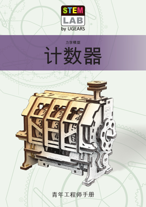
STEM-LAB系列计数器手册说明书
指示器
计数器
5
§3 关于该机械装置及其使用范围
根据已知情况,我们可以确定里程表类型包括: 机械里程表——机械传感器+机械计数器。其装置结构最为简单,工作原理是通过电缆将旋转数直接传输 到计数器机械装置内。 混合型或机电里程表——机械传感器+电子计数器。在这种情况下,电缆的物理旋转驱动计数器机械装置, 但指示器是数字指示器,因此计数器机构的操作是数字式的。 数字里程表——机电传感器+电子计数器。这是最新的商业应用系统。传感器检测转数并将其转换为电子 脉冲,电子脉冲在计数器中解读后传输到指示器。 那么,知道行驶距离的重要性何在? 其实,里程表有助于确定道路里程(如汽车里程数),可以让驾驶员了解下次维修保养的时间。在形成开始前 将里程表(或标记数字)归零时,就可以计算出从起点到终点的距离。也可以通过满油箱行驶距离来计算里程。 此外,购买或出售汽车时,汽车剩余寿命通常由行驶里程决定,行驶里程会对价格有所影响。 里程决定的士收费等。 通常,为了方便司机查看,汽车里程表就设置在速度表旁边,为判定车速提供了另一种机械装置。 里程表系统的构件里有计数器,那么该里程表是机械里程表。 仔细观察当传感器启动时,机械计数器内部的边画画。 仔细观察机械汽车里程表。 其工作原理是计算车轮转数,每公里转数不变。在行程中车轮转数已知的情况下,就很容易计算出车辆行 驶距离。
蜗轮(交叉斜齿轮)是 一种机械齿轮装置,其中 的蜗杆与蜗轮相咬合。
7
§3 关于该机械装置及其使用范围
为确保显示精度,驾驶员/用户在车轮直径 改变等情况下需校准里程表。
现在,我们已经知道了里程表的定义,下面 我们就要通过实践检验其工作,实践方式就 是使用新组装的机械拼图。你手上的模型是 用计数器和指示器组装的。而检测员就是你, 你要按下点击按钮或转动模型右侧的手柄!
通用计数器使用说明书SS7200A

仪器处于测量频率状态
+Wid
仪器处于测量正脉宽状态
-Wid
仪器处于测量负脉宽状态
石家庄市无线电四厂 石家庄数英电子仪器有限公司
19
Rise Fall Time Ch 1 Ch 2 Ch 3 Limit
ExtRef Hz M μ S Gate
SS7200A 通用计数器
用户使用指南
仪器处于测量上升时间状态 仪器处于测量下降时间状态 仪器处于测量时间间隔状态 仪器的通道1正作为一个信号输入端 仪器的通道2正作为一个信号输入端 仪器的通道3正作为一个信号输入端 仪器正处于极限测量状态并且测出的值不在用户预先设置 的范围 仪器正在使用从后面板的Ref In输入的频标作为频标信号 显示的数据以Hz为单位 即106,作为要显示单位的前缀 即10-6,作为要显示单位的前缀 显示的数据以秒为单位 表示闸门打开。在测量开始之前,此位是熄灭的,表明闸门未打开;在 测量过程中,此为为亮,表示闸门打开。
【50Ω/1MΩ】
50Ω或高阻选择键,灯亮为 50Ω,熄灭为 1MΩ,默认
为高阻
【DC/AC】
交直流选择键,仪器默认为 AC,LED 灯不亮;选为 DC
时,LED 灯点亮
【×10Att】
衰减键,仪器默认状态为不衰减,键灯不亮;当选为衰
减时,LED 灯被点亮
【100kHz Filter】 滤波键,仪器默认状态为不滤波,LED 灯不亮;
2只
z 用户使用说明书
1本
SS7200A 通用计数器选件
z IEEE488 通用接口
1套
z RS232 通用接口
1套
z 3GHz 输入通道
1套
石家庄市无线电四厂 石家庄数英电子仪器有限公司
- 1、下载文档前请自行甄别文档内容的完整性,平台不提供额外的编辑、内容补充、找答案等附加服务。
- 2、"仅部分预览"的文档,不可在线预览部分如存在完整性等问题,可反馈申请退款(可完整预览的文档不适用该条件!)。
- 3、如文档侵犯您的权益,请联系客服反馈,我们会尽快为您处理(人工客服工作时间:9:00-18:30)。
智能计数器说明书1.性能指标计数范围:999999计数频率:0-1000HZ输入电压:220V AC±5%输出形式(可选):TTL电平输出继电器输出通讯模式:支持RS485接口基于MODEM-BUS协议波特率1200bit/s-9600bit/s功能特点:三种清零方式三种启停计数方式四种工作模式停止计数时数据保存支持多机通讯与控制2.工作模式工作模式1:当计数达到计数上限时,计数器停止计数,输出报警信号.工作模式2:当计数达到计数上限时,计数器继续计数,输出报警信号.工作模式3:当计数达到计数上限时,计数器自动清零,同时输出报警信号.(注:报警信号只维持10ms 左右.)工作模式4:不停止计数,每间隔计数报警上限的整数倍时,输出报警信号.(注:报警信号只维持10ms 左右.)3.键盘操作说明面板键盘有四个键,可完成控制器的功能设置与工作模式的转换.复位键:当系统死机或工作不正常时,可以按压复位键强制计数器复位.设置键:按压设置键进行页选择,每一页代表一项功能项.上下键:在设置状态时,完成数据的修改.下键与设置键组合:在计数状态时,可完成计数器清零.上键:在计数状态时,可完成启停计数器计数.按压设置键可以使计数器进入设置状态.在计数器为设置状态时,不按任何键2S后,计数器返回计数状态.计数器共有6个设置页.计数器第二行的两位LED表示哪一个设置页.1)清零方式选择:按压设置键直到功能页显示1.后, 按压上下↑或↓可加减设置值.00:表示使用手动清零.即在计数状态时,按压下键与设置键组合完成计数器清零. 01:表示使用外部引脚清零.即在计数状态时,将FWR与FERG短接150ms即可完成计数器清零.02:表示使用串口清零.即在计数状态时,由上位机发送清零命令,即可完成计数器清零.2)计数器启停方式选择:按压设置键直到功能页显示2.后, 按压上下↑或↓可加减设置值.00:表示使用手动启停.即在计数状态时,按压上键即可启停计数器计数.01:表示使用外部引脚启停.即在计数状态时,将WSS与WSSG短接150ms即可启停计数器计数.02:表示使用串口启停.即在计数状态时,由上位机发送启停命令,即可启停计数器计数.3)工作方式选择:按压设置键直到功能页显示3.后, 按压上下↑或↓可加减设置值.00:使用工作模式1.01:使用工作模式2.02:使用工作模式3.03:使用工作模式4.4)波特率选择:按压设置键直到功能页显示4.后, 按压上下↑或↓可加减设置值.00:1200 bit/s01:2400 bit/s02:4800 bit/s03:2400 bit/s5)地址设置按压设置键直到功能页显示5.后, 按压上下↑或↓可加减设置值.地址设置范围: 00-2556)计数报警上限设置按压设置键直到功能页显示6.后, 按压上下↑或↓可加减设置值.计数报警上限设置范围:000001-99999994.外观说明产品外观见图1.图15.通讯说明控制器采用RS-485总线,协议符合ModBus RTU规约.数据传输均采用8位数据位,1位停止位,无奇偶校验位.波特率可设为1200-9600 bit/s. 通讯传送分为独立的信息头,和发送的编码数据.以下的通讯传送方式定义与RTU通讯规约相兼容:编码8位二进制起始位1位数据位8位奇偶校验位无停止位1位错误校检CRC(冗余循环码)初始结构= >=4字节的时间地址码= 1 字节功能码= 1 字节数据区= N 字节错误校检= 16位CRC码结束结构= >=4字节的时间地址码:地址码为通讯传送的第一个字节.这个字节表明由用户设定地址码的从机将接收由主机发送来的信息.并且每个从机都有具有唯一的地址码,并且响应回送均以各自的地址码开始.主机发送的地址码表明将发送到的从机地址,而从机发送的地址码表明回送的从机地址.功能码:通讯传送的第二个字节.ModBus通讯规约定义功能号为1到127.本控制器利用其中的一部分功能码.作为主机请求发送,通过功能码告诉从机执行什么动作.作为从机响应,从机发送的功能码与从主机发送来的功能码一样,并表明从机已响应主机进行操作.如果从机发送的功能码的最高位(比如功能码大于127),则表明从机没有响应操作或发送出错.数据区:数据区是根据不同的功能码而不同.CRC码:二字节的错误检测码.当通讯命令发送至仪器时,符合相应地址码的设备接通讯命令,并除去地址码,读取信息,如果没有出错,则执行相应的任务;然后把执行结果返送给发送者.返送的信息中包括地址码,执行动作的功能码,执行动作后结果的数据以及错误校验码.如果出错就不发送任何信息.1.结构:地址码功能码数据区校验码8位8位N × 8or16位16位2.信息帧格式:地址码:地址码是信息帧的第一字节(8位),从0到255.这个字节表明由用户设置地址的从机将接收由主机发送来的信息.每个从机都必须有唯一的地址码,并且只有符合地址码的从机才能响应回送.当从机回送信息时,相当的地址码表明该信息来自于何处.功能码:主机发送的功能码告诉从机执行什么任务.表2列出的功能码都有具体的含义及操作. 表1 功能码代码含义操作03读取数据读取当前寄存器内一个或多个二进制值06重置单一寄存器把设置的二进制值写入单一寄存器(3)数据区:数据区包含需要从机执行什么动作或由从机采集的返送信息.这些信息可以是数值,参考地址等等.例如,功能码告诉从机读取寄存器的值,则数据区必需包含要读取寄存器的起始地址及读取长度.对于不同的从机,地址和数据信息都不相同.(4) 错误校验码:主机或从机可用校验码进行判别接收信息是否出错.有时,由于电子噪声或其它一些干扰,信息在传输过程中会发生细微的变化,错误校验码保证了主机或从机对在传送过程中出错的信息不起作用.这样增加了系统的安全和效率.错误校验采用CRC-16校验方法.CRC码低字节在前.注:信息帧的格式都基本相同:地址码,功能码,数据区和错误校验码.3.错误校验参与冗余循环码(CRC)计算的包括:地址码,功能码,数据区的字节.冗余循环码包含2个字节,即16位二进制.CRC码由发送设备计算,放置于发送信息的尾部.接收信息的设备再重新计算接收到信息的CRC码,比较计算得到的CRC码是否与接收到的相符,如果两者不相符,则表明出错.CRC码的计算方法是,先预置16位寄存器全为1.再逐步把每8位数据信息进行处理.在进行CRC码计算时只用8位数据位,起始位及停止位,如有奇偶校验位的话也包括奇偶校验位,都不参与CRC码计算.在计算CRC码时,8位数据与寄存器的数据相异或,得到的结果向低位移一字节,用0填补最高位.再检查最低位,如果最低位为1,把寄存器的内容与预置数相异或,如果最低位为0,不进行异或运算.这个过程一直重复8次.第8次移位后,下一个8位再与现在寄存器的内容相异或,这个过程与以上一样重复8次.当所有的数据信息处理完后,最后寄存器的内容即为CRC码值.计算CRC码的步骤为:(1).预置16位寄存器为十六进制FFFF(即全为1).称此寄存器为CRC寄存器;(2).把第一个8位数据与16位CRC寄存器的低位相异或,把结果放于CRC寄存器;(3).把寄存器的内容右移一位(朝低位),用0填补最高位,检查最低位(注意:这时的最低位指移位前的最低位,不是移位后的最低位);(4).如果最低位为0:重复第3步(再次移位)如果最低位为1:CRC寄存器与多项式A001(1010 0000 0000 0001)进行异或;(5).重复步骤3和4,直到右移8次,这样整个8位数据全部进行了处理;(6).重复步骤2到步骤5,进行下一个8位数据的处理;(7).最后得到的CRC寄存器即为CRC码.4. 功能码03,读取点和返回值:利用通讯命令,可以进行读取点("保持寄存器") 或返回值("输入寄存器" ).一次最多可读取寄存器数是15.由于一些可编程控制器不用功能码03,所以功能码03被用作读取点和返回值.从机响应的命令格式是从机地址,功能码,数据区及CRC码.数据区的数据都是每二个字节高位在前,CRC码低位在前高位在后.信息帧格式举例:从机地址为00,起始地址0008H的1个寄存器. 此例中寄存器数据地址为:地址数据0008 02H主机发送字节数举例从机地址1 00 发送至从机00功能码1 03 读取寄存器起始地址2 00 起始地址为000808读取点数2 00 读取1个寄存器01CRC码2 04 由主机计算得到的CRC码19从机响应字节数举例从机地址1 00 来自从机00功能码1 03 读取寄存器读取字节数1 02 寄存器字节总数寄存器数据2 0002 地址为0008内的内容CRC码2 04 由从机计算得到的CRC码45表2 功能码03读取的数据及地址地址内容地址内容地址内容0000H计数数据低位字0005H系统保留000AH工作模式选择寄存器0001H计数数据高位字0006H系统保留000BH启停状态查看寄存器0002H设置计数报警上限低字0007H系统保留0003H设置计数报警上限高字0008H清零模式选择寄存器0004H系统保留0009H启停模式选择寄存器表3 数据计算方法参数计算方法数据格式备注计数数据计数数据高位字×65536+计数数据低位字原码应连续读取两个寄存器组合后,方可合成计数数据计数报警上限计数报警上限高位字×65536+计数报警下限低位字原码应连续读取两个寄存器组合后,方可合成计数数据表4其他寄存器的功能说明名称含义启停状态查看寄存器00:计数器处在不计数状态01:计数器处在不计数状态5. 功能码06,单点保存:主机利用这条命令把单点数据保存到控制器的存储器.控制器也用这个功能码向主机返送信息.信息帧格式举例:控制器地址为00,保存起始地址0008的1个值.在此例中,数据保存结束后,控制器中地址为0008内的内容为02H.主机发送字节数举例从机地址1 00 发送至从机00功能码1 06 单点保存起始地址2 00 起始地址为000808保存数据2 00 保存的数据为02H02CRC码2 88 由主机计算得到的CRC码18从机响应字节数举例从机地址1 00 来自从机00功能码1 06 单点保存起始地址2 00 起始地址为000808保存数据2 00 保存的数据为02H02CRC码2 88 由主机计算得到的CRC码18表5 功能码06保存的数据及地址地址内容0002H设置计数报警上限低字0003H设置计数报警上限高字0008H清零模式选择寄存器0009H启停模式选择寄存器000AH工作模式选择寄存器000BH启停计数器计数000CH计数器清零表6 个别寄存器说明地址内容说明000BH启停计数器计数向寄存器写"1"启动计数写"0"停止计数.(注:启停模式选择为串口启停)000CH计数器清零向寄存器写"1" 计数器清零.(注:清零模式选择为串口清零)6.数据错误返回值:如果主机发出的数据错误,则控制器向主机回送错误信息,功能码的最高位为1,即控制器返回给主机的功能码是在主机已送的功能码上加128.从机返回的错误码的格式如下:地址码:1字节功能码:1字节(最高位为1)错误码:1字节CRC码:1字节错误码为00H6.接线说明外形尺寸及开孔尺寸外形尺寸:160×78×80控制器接线图控制器接线图FWRG与FWR 为外部清零引脚:当清零方式选择为使用外部清零时,在计数状态短接150ms,即可完成计数器清零.WSSG与WSS 为外部启停引脚:当启停方式选择为使用外部启停时,在计数状态短接150ms,即可完成计数器计数启停.INTG与INT 为脉冲输入引脚:INTG联接内部光耦的负极,INT联接内部光耦的正极OUT1与OUT2 为报警输出引脚:继电器输出时,报警为吸合.TTL电平输出时,报警为OUT2输出高,OUT1输出低.使用说明书。