
台德TC-60KA计数器说明书
Relay action ,holdtime
Mode Key
Ouput Index Lamp
外形尺寸图 Dimension Diagram
现在值归零键 Reset Key
( Unit: mm )
7.5
110.0
91.0
48.0
44.0
盘面开孔 Panel cut-out
端子说明 Connection Diagram
then the counter will keep on counting,and the relay will return to the original condition after several seconds.
SW1-2:开关 SW1-2:Switch
计数方式(Counting Method) 1:Sw1-2 OFF: 单相加算,单相减算(单相入力)
A_in: 2 pin B_in: 4 pin
“H” “L” “H” “L”
T/4 T/4 T/4 T/4
T
8 pin Vout 3 pin 0V
SW1
Key lock
54321
ON
54321
54321
54321
ON
R return
ON
C return
ON SW1
90° quadrature input
function mode is selected, trying to hold Sw1-5 in the “ON” condition to keep from man-made mistakes.
SW1-3,SW1-4: 开关 SW1-3,SW1-4: Switch
Relay 复归 N.R.C. Relay reture N.R.C 1: N: 手动(MANUAL)SW1-3 OFF, SW1-4 OFF.
Sw1 -5 ON 时,无法选择设定功能,Sw1-5 OFF 时方可选择设定功能,在设定功能完成后,尽量
保持 Sw1-5 在 ON 的位置,以免人为操作失误。
When Sw1-5 is ON,the function can’t be set. Just as Sw1-5 OFF, then the function can be selected. When the
NPN transistor voltage output R2
1 pin 12V
SW1-1: 输入频率开关 SW1-1 Switch
1: SW1-1 为 OFF 时,信号无滤波电容,频率可达 1KHz。
R1
SW1
R3
54321
When SW1-1is “OFF”, Removes damping capacitor and allows operation up to 1KHz.
ON
54321
6 位数按键设定式计数器
6 DIGIT KEYBOARD PRESET COUNTER
产品规格 Specification
型号规格 Item No
TC – 60KA
显示范围 Display Range 设定范围 Setting Range 显示尺寸 Display Height 计数输入 Input Signal Mode 输出方式 Output System 输出时间 Output Hold Time 复归方式 Reset System 输入信号 Input Level 停电记忆 Power Failure Memory 信号电源 DC Out For Sensor 电源电压 Power Supply 消耗功率 Power Consumpion
耐温湿度 Operating Temperature Humidity
- 10℃ ∽ +50℃ 35 % ∽ 85 % RH
外形尺寸 External Dimensions
96mm × 48mm × 123mm (盘面开孔 Mounting Flush Dimension:92mm × 45mm)
面板说明 Panel Explanation
Shift 键 Shift Key
决定设定类别或结束设定。 Used to change display mode or operation mode, and when the function setups over,please press this key
▲ ▲
▲ ▲
设定 Relaly 动作保持时间。 设定功能键
External,, Manual, AutoReset
NPN, Open Collector
EEPROM Memory Keep Ten Years 12V DC ±5 % Max Electric Current Capacity 100Ma
AC 110V/220V ±15 % 50Hz/60Hz 5.5 VA
Sw1-2 OFF: single addition, single dection (single phase)
A_in: 2 pin 加算输入 addition
B_in: 4 pin 减算输入 dection
T/2 T/2 T
“H” “L”
2:Sw1-2 ON: 加减算(90°相位差输入)
Sw1- 2 ON:addition and subtraction ( Quadrature input) 此计数模式常配合译码器(encoder)使用,或配合两个 sensor,但要注意相位差尽量为 90°。
2: SW1-1 为 ON 时,信号有滤波电容,频率可达 25Hz。
HI
LO
When SW1-1is “OFF”, Connects small damping capacitor and
limits counter frequency to 25Hz.
ON
SW1-5:开关 SW1-5:Switch
reset 键 reset Key
在按下此键时,现在值清除为零。 Press the key to clear the current displayed value.
设定流程 Preset Step
设定类别 Setup type
步骤 step
mode
mode ---
mode mode
shift
01.0000
TaiDe
timer
mode shift
Relay
COUNTER
1(HI)
2(LO) 动 作
3(GO) 灯
▲ቤተ መጻሕፍቲ ባይዱ
reset
Mode 键 选择设定功能类别
(1) :倍率设定,范围 0.0001 ∽ 99.9999。 (2) :小数点位置设定。 Used to change display mode or operation mode (1) :Percentage setup, range 0.0001∽99.9999. (2) :Decimal point setup.
N return
计数值等于设定值时 Relay ON,计数值继续上数,直到手动或外部复归时,Relay 才复归,值归零。
When the counting value is qual to the preset value,the relay will turn on.The counter will keep counting up until we press down the “reset” button or connects the terminal 3 & 5 together at the same time,then
计数值等于设定值时 Relay ON,计数值立即归零后继续上数,而 Relay 到时间(由 timer 键设定)后复归。
When the counting value is qual to the preset value,the relay will turn on and the display returns to zero.
This quadrature counting mode can be implemented by the
rotary encoder or two sets of photoelectric sensors. 3:注意在改变计数模式后,必须切断电源再重新通电开机。
You must turn on the counter again when change the mode of the counter
- 99999 ∽ 999999 1 ∽ 999999
Count LED 0.56” (RED) 有接点输入 Contact Input:25HZ 无接点输入 NO Contact Input:1kHZ
Relay Ouput (AC 250V/3A) 0.1 ∽ 9.9 Seconds (Variable)
12V A_in 0V B_in RS
1234 56 7
54321
8 9 10 11 地 中 相
110V 220V
键:设定位数左移。
Move left to select the seting opsition.
▲ 键:位数值加 1,按住不放则连续递增。
The preset value add one, pressing the pushbutton ,the preset value go on adding to reachs the desired value.
but after several seconds, the relay returns to the original condition and the display value will return to zero. 3: C: 继续 (CONTINUE)SW1-3 OFF, SW1-4 ON.
达克制造公司60英寸冷藏背部计数器数字说明书
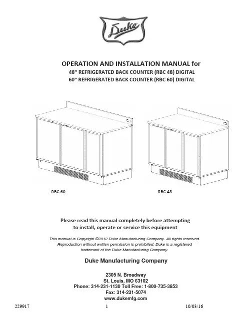
OPERATION AND INSTALLATION MANUAL for 48” REFRIGERATED BACK COUNTER (RBC 48) DIGITAL60” REFRIGERATED BACK COUNTER (RBC 60) DIGITALPlease read this manual completely before attemptingto install, operate or service this equipmentThis manual is Copyright ©2012 Duke Manufacturing Company. All rights reserved.Reproduction without written permission is prohibited. Duke is a registeredtrademark of the Duke Manufacturing Company.Duke Manufacturing Company2305 N. Broadway St. Louis, MO 63102Phone: 314-231-1130 Toll Free: 1-800-735-3853Fax: 314-231-5074 RBC 60RBC 48IMPORTANT WARNING AND SAFETY INFORMATION WARNING: READ THIS MANUAL THOROUGHLY BEFORE OPERATING,INSTALLING OR PERFORMING MAINTENANCE ON THE EQUIPMENT.FAILURE TO FOLLOW INSTRUCTIONS IN THIS MANUAL CAN CAUSEPROPERTY DAMAGE, INJURY OR DEATH.DO NOT STORE OR USE GASOLINE OR OTHER FLAMMABLE VAPORSOR LIQUIDS IN THE VICINITY OF THIS OR ANY OTHER APPLIANCE.UNLESS ALL COVER AND ACCESS PANELS ARE IN PLACE ANDPROPERLY SECURED, DO NOT OPERATE THIS EQUIPMENT.CAUTION: OBSERVE THE FOLLOWING:•Minimum clearances must be maintained from all walls and combustible materials.• Keep the equipment area free and clear of combustible material.• Adequate clearance for air openings.• Unit exhausts air to the bottom and the rear.• Do not set unit on a curb or seal to the wall.• Do not block the slots in the front kickplate• Operate equipment only on the type of electricity indicated on the specification plate.• Retain this manual for future reference.Table of Contents: Introduction (4)Serial Number (4)Receiving & Inspecting the Equipment (5)Specifications (5)Installation (5)Location (5)Inside Unit (6)Leveling (6)Stabilizing (6)Electrical Connection (6)Operation (7)Location of Controls (7)Operating Procedure (7)Energy Mode Switch (7)Maintenance (7)Stainless Steel care & Cleaning (7)Cleaning the Condensor Coil (8)Door Gasket Care (9)Drain Maintenance (9)Drain Pan Access (10)INTRODUCTIONThis publication contains information regarding the installation and operation of Duke Refriger-ated Back Counter units. The information contained within applies to the models RBC 48 and RBC 60. Please read this manual completely before attempting to install and/or operate this equipment.Model number RBC 48 describes the 48” wide version of the Refrigerated Back Counter. (Fig. 1)Model number RBC 60 describes the 60” wide version of the Refrigerated Back Counter. (Fig. 2)SERIAL NUMBERAlways have the serial number of your unit available when calling for parts or service.Figure. 1 RBC 48Figure. 2 RBC 60RECEIVING & INSPECTING THE EQUIPMENTCare should be taken during unloading so the equipment is not damaged while being moved into the building.1. Visually inspect the exterior of the package and skid or container. Any damage should be noted and reported to the delivering carrier immediately.2. If damaged, open and inspect the contents with the carrier.3. In the event that the exterior is not damaged, yet upon opening, there is concealed damage to the equipment notify the carrier. Notification should be made verbally as well as in written form.4. Request an inspection by the shipping company of the damaged equipment. This should be done within 10 days from receipt of the equipment.5. Check the lower portion of the unit to be sure legs/casters are not bent.6. Also view compressor compartment housing and visually inspect the refrigeration package. Be sure lines are secure and base is still intact.7. Freight carriers can supply the necessary damage forms upon request. 8. Retain all shipping material until an inspection has been made or waived.SPECIFICATIONSINSTALLATION - LocationUnits represented in this manual are intended for indoor use only. Be sure the location chosen has a floor or counter strong enough to support the total weight of the units. Reinforce the floor or counter if necessary to provide for maximum loading. For the most efficient operation, be sure to provide good air circulation inside and out. These units should be located so that they can be moved for service. Major service to the refrigeration system is done from the end of the cabinet.The outline dimensional drawings for the units are shown in Figures 3 and 4.MODEL DESCRIPTIONVOLTAGE AMPS PHRBC 4848” Refrigerated Back Counter48” Refrigerated Back Counter with Energy Star120 VAC (60 Hz) 230 VAC (50 Hz)120 VAC (60Hz) 220 VAC (50Hz) 6 (max) 3 (max)5.5 (max) 2.5 (max) 1 1 1 1RBC 6060” Refrigerated Back Counter60” Refrigerated Back Counter with Energy Star120 VAC (60 Hz) 220 VAC (50 Hz)120 VAC (60 Hz) 220 VAC (50 Hz) 6 (max) 3 (max)5.5 (max) 2.5 (max) 1 1 1 1MODEL DESCRIPTIONHEIGHT WIDTH LENGTHRBC 48 48” Refrigerated Back Counter40.00 In.29.50 In.48.00 In.RBC 6060” Refrigerated Back Counter40.00 In.29.50 In.60.00 In.INSTALLATION – Inside UnitTake care not to block air flow to the fans and allow space along the front, back and sides.INSTALLATION – Outside UnitBe sure that the unit has access to ample air; avoid hot corners and locations near stoves and ovens.CAUTION:This unit exhausts air to the bottom and the back. Do not seal the unit to the wall or set unit on a curb. The ventilation slots in the kickplate must remain open.INSTALLATION – LevelingBe sure that the units are placed on a firm, flat surface/floor. Check for cracks in flooring or tile and avoid these areas if possible. If necessary place support pads, properly rated for the weight of the unit, to “bridge” uneven or cracked flooring. Level unit accordingly.INSTALLATION – StabilizingUse the leg adjustments to insure that the unit is solid to the floor surface at all four contact points. Insure that the unit does not “rock” when pressure is applied to the top corners.INSTALLATION – Electrical WiringThe RBC 48 and RBC 60 are available as a 120VAC, 60 Hz or as 220VAC, 50 Hz dependent on model. All electrical connections should be performed by a certified electrician and should comply with local electrical codes for your municipality.WARNING:REFER TO THE AMPERAGE DATA LIST IN THE SPECIFICATIONS OR THE SERIAL TAG DATA AND YOUR LOCAL CODE OR THE NATIONAL ELECTRICAL CODE TO BE SURE UNIT IS CONNECTED TO THE PROPER POWER SOURCE. A PROTECTED CIRCUIT OF THE CORRECT VOLTAGE AND AMPERAGE MUST BE RUN FOR CONNECTION OF THE SUPPLY CORD OR PERMANENT CONNECTION TO THE UNIT. THE POWER MUST BE TURNED OFF AND DISCONNECTED WHENEVER PERFORMING MAINTENANCE OR REPAIR FUNCTIONS.Figure. 3 RBC 48Figure. 4RBC 60OPERATION – Location of ControlsThe refrigeration control/temperature setting adjustment is located on the back splash. The energy saving mode switch (if equipped) is located inside the right front access panel. (See figure 5 & 6.) Remove front panel and access plate.These are the only user adjustable components on the unit.OPERATION – Operating ProcedurePress and hold the (i) button to display setpoint. Keep (i) button pressed and use the up/down arrows to adjust setpoint. When the (i) button is released, the new setpoint is stored. To exit from the setup, press the power button or wait 30 seconds. Display will display “dEF” while unit is in defrost mode. Check the cooling specifications required for the products/goods to be stored.Use a simple thermometer to set to a specific temperature. Allow time for temperature chang -es before making a final temperature check.OPERATION – Energy Mode SwitchWhen the mode switch (if equipped) is set to “energy save” mode, the condensate heaters around the door openings are de-energized to reduce power consumption. If condensation forms around the doors, then turn this switch to “normal” mode.MAINTENANCE – Stainless Steel Care & CleaningTo prevent discoloration or rust on stainless steel several important steps need to be taken. Stainless steel contains 70-80% iron which will rust. It also contains 12-30% chromium which forms an invisible passive film over the steels surface which acts as a shield against corrosion. As long as the protective layer is intact, the metal will not corrode. If the film is broken or contaminated, outside elements can begin to breakdown the steel and begin to form rust or discoloration.Figure. 6MAINTENANCE – Stainless Steel Care & Cleaning – cont.Proper cleaning of stainless steel requires soft cloths or plastic scouring pads.CAUTION: Never use steel pads, wire brushes or scrapers.Cleaning solutions need to be alkaline based or non-chloride cleaners. Any cleaner containing chlorides will damage the protective film of the stainless steel. Chlorides are also commonly found in hard water, salts and household and industrial cleaners. If cleaners containing chlorides are used, be sure to rinse repeatedly and dry thoroughly upon completion.Routine cleaning of stainless steel can be done with soap and water. Extreme stains or grease should be cleaned with a non-abrasive cleaner and plastic scrub pad. It is always good to rub with the grain of the steel. There are also stainless steel cleaners available which can restore and preserve the finish of the steels protective layer.Early signs of stainless steel breakdown can consist of small pits and cracks. If this has begun, clean thoroughly and start to apply stainless steel cleaners in attempt to restore the passivity ofMAINTENANCE – Cleaning the Condenser CoilThe condenser coil is located behind the filter panel and is accessed through the front of the unit (See Figure 7). Filter can be cleaned by rinsing with water. Allow to dry completely before reinstalling. The condenser coil requires regular cleaning and is recommended every 60 days. However, in some instances you may find that there is a large amount of debris, dust or grease that has accumulated prior to the 60 day time frame. In these cases the condenser coil should be cleaned every 30 days.Figure. 7MAINTENANCE – Cleaning the Condenser Coil – cont.If the build up on the coil consists of only light dust and debris the condenser coil can be cleaned with a simple brush, heavier dust buildup may require a vacuum or even compressed air to blow through the condensor coil.If heavy grease is present degreasing agents are available for refrigeration use and specifically for the condenser coils. The condenser coil may require a spray with the degreasing agent and then blown through with compressed air.Failure to maintain a clean condenser coil can initially cause high temperatures and excessive run times. Continuous operation with dirty or clogged condenser coils can result in compressor failures. Neglecting the condenser coil cleaning procedures will void any warranties associated with the compressor or cost to replace the compressor.CAUTION:NEVER USE A HIGH-PRESSURE WATER WASH FOR THIS CLEANING PROCEDURE AS WATER CAN DAMAGE ELECTRICAL COMPONENTS LOCATED NEAR OR AT THE CONDENSER COIL. MAINTENANCE – Door Gasket CareGaskets require regular cleaning to prevent mold and mildew build up and also to keep the elasticity of the gasket. Gasket cleaning can be done with the use of warm soapy water. Avoid full strength cleaning products on gaskets as this can cause them to become brittle and prevent proper seals. Also, never use sharp tools or knives to scrape or clean the gasket which could possibly tear the gasket and rip the bellows.Gaskets can easily be replaced and do not require the use of tools or authorized service persons. The gaskets are “Dart” style and can be pulled out of the grove in the door and new gaskets can be “pressed” back into place.MAINTENANCE – DrainEach unit has a copper drain tube located inside the unit which removes condensation from the evaporator coil and deposits it onto a drain pan where it can evaporate (See Fig. 8). If you notice excessive water accumulation on the inside of the unit be sure that the drain tube is connected from the evaporator housing to the condensate evaporator drain pan. If water is collecting underneath the unit you may want to check the condensate evaporator drain tube to be sure it is still located above the drain pan. The leveling of the unit is also important as the units are designed to drain properly when on a level surface, if your floor is not level this can also cause drain problems. Be sure the drain pan is kept free of dirt, dust and other debris as excessive amounts wi ll cause water to back up and overflow from the drain pan.MAINTENANCE – Drain Pan AccessThe drain pan and drain tube can be accessed from the rear of the unit. Pull the unit away from wall to expose the opening in the rear of the cabinet. The drain pan is located under the refrigeration system unit (see fig. 8)NOTES229917 11 10/03/16229917 12 10/03/16Duke Manufacturing Company 2305 N. Broadway St. Louis, MO 63102 Phone: 314-231-1130 Toll Free: 1-800-735-3853 Fax: 314-231-5074 。
流量计仪表操作说明
目录仪表的键盘和前面板-------------------------------------2 仪表功能----------------------------------------------------4 仪表程序----------------------------------------------------4 仪表键盘和中控方式的转换----------------------------6 仪表的启动和停止----------------------------------------7 仪表重量和容积方式的转换----------------------------8 给定量的输入----------------------------------------------8 显示事件信息----------------------------------------------8 服务数据----------------------------------------------------9 标定功能----------------------------------------------------9 调零-----------------------------------------------------14 计数器1或2的复位-------------------------------------13 安装与调整-------------------------------------------------13 维护与保养-------------------------------------------------14 事件信息----------------------------------------------------16(一)仪表的键盘1各按键的作用如下:启动键和停止键。
定时器计数器(TC)简介以及例子说明
定时器/计数器(T/C)简介一、定时器/计数器有关的特殊功能寄存器1. 计数数寄存器TH和TL计数器寄存器是16位的,计数寄存器由TH高8位和TL低8 位构成。
在特殊功能寄存器(SFR)中,对应T/C0为TH0和TL0,对应T/C1为TH1和TL1。
定时器/计数器的初始值通过TH1/TH0和TL1/TL0设置。
2. 定时器/计数器控制寄存器TCONTR0,TR1:T/C0,1启动控制位。
1——启动计数0——停止计数TCON复位后清“0”,T/C需受到软件控制才能启动计数,当计数寄存器计满时,产生向高位的进位TF,即溢出中断请求标志。
3. T/C的方式控制寄存器TMODT/C1 T/C0 C/T :计数器或定时器选择位。
1——为计数器0——为定时器GATE:门控信号1——T/C的启动受到双重控制,即要求TR0/TR1和INT0/INT1同时为高。
M1和M0:工作方式选择位。
(四种工作方式)4.定时器/计数器2(T/C2)控制寄存器TF2:T/C2益出标志——必须由软件清除EXF2:T/C2外部标志。
当EXEN2=1,且T2EX引脚上出现负跳变而引起捕获或重装载时置位,EXF2要靠软件来清除。
RCLK:接收时钟标志1——用定时器2 溢出脉冲作为串行口的接收时钟0——用定时器1的溢出脉冲做接收时钟。
TCLK:发送时钟标志。
1——用定时器2 溢出脉冲作为串行口的发送时钟0——用定时器1的溢出脉冲作发送时钟EXEN2:T/C2外部允许标志。
1——若定时器2未用作串行口的波特率发生器,T2EX端的负跳变引起T/C2的捕获或重装载。
0——T2EX端的外部信号不起作用。
TR2:T/C2运行控制位1——T/C2启动0——T/C2停止C/T2:计数器或定时器选择位1——计数器0——定时器CP/RL:捕获/重载标志。
1——若EXEN2=1,且T2EX端的信号负跳变时,发生捕获操作。
0——若定时器2溢出,或在EXEN2=1条件下T2EX端信号负跳变,都会造成自动重装载操作。
TC系列多路温度测试仪说明书

TC系列多路温度测试仪说明书OPERATION MANUALTC系列多路温度测试仪1目录第一章快速入门 (5)1.1 前面板介绍 (5)1.2 后面板介绍 (5)1.3 按键功能描述 (6)1.4 指示灯功能描述 (6)1.5 出厂标准附件 (7)第二章技术规格 (7)主要技术参数 (7)2.12.2 补充特性 (7)第三章面板操作 (8)3.1 基本测量模式3.1.1 定点测量模式 (8)3.1.2 巡检测量模式 (8)3.2 设置操作 (8)第四章仪器通讯协议 (10)4.1 通讯设置 (10)4.2 帧格式 (10)4.3串口通讯命令字快速扫描 (11)4.4命令字的使用 (11)第五章注意事项 (16)第六章常见问题及解决方法 (16)6.1 仪器开机不能正常显示 (16)6.2 温度测量结果不对及出错 (17)2安全请勿自行在仪器上安装替代零件,或执行任何未经授权的修改。
请将仪器送回给威博科技有限公司的维修部门进行维修,以确保其安全特性。
请在购买和使用仪器前仔细参考本手册,以避免产生经济纠纷或仪器损坏。
仪器内部无操作人员可维修的部件。
若需维修服务,请联络受过训练的维修人员。
品质保证TC系列多路温度测试仪完全达到手册中所标称的各项技术指标。
售后服务威博科技有限公司承诺对本产品自购买日期起给予一年的质量保证~服务限制售后服务不适用于因以下情况所造成的损坏:顾客不正确或不适当的维修产品;未经授权的修改和误用;顾客自行安装的电路造成的损坏,或顾客使用自己的产品造成的瑕疵。
通告本手册的内容如有更改,恕不另行通知。
注意为了保证测量精度,建议开机十分钟后开始操作3简介TC系列多路温度测试仪,适用于家电、电机、电热器具等行业的制造厂家和质检部门对温度参数的测量。
为了满足用户的需求,用户可以进行如下选择:8路或16路温度测量、是否配置微型打印机。
本系列产品具有如下功能和优点: , 通过仪器设置,用户可以选择使用铜/铜镍(T型)、镍铬/镍硅(K型)或铁/铜镍(J型)热电偶, 在被测物带电的情况下,仪器可以继续测量使用, 在仪器总的巡检路数范围之内,用户可以选择任何几路进行测量 , 三种巡检速度选择:0.2S、0.4S、1.0S, 两种测量模式选择:定点、巡检, 可以设置测量温度上、下限和报警提示, 具有定时打印功能,并可以设置定时打印间隔时间(在配置微型打印机的情况下), 数字LED显示, 按键操作, 断电设定数据保持记忆功能, 错误自动检测和报警、显示闪烁提示, 可通过计算机进行软件监控附:如客户需要温控器功能,需特别声明。
TC 系列控制台用户操作手册说明书
◆慎重保证本公司生产的产品,在发货之日起三个月内,如产品出现缺陷,实行包换。
三年(包括三年)内如产品出现缺陷,实行免费维修。
三年以上如产品出现缺陷,实行有偿终身维修。
◆安全要求请阅读下列安全注意事项,以免人身伤害,并防止本产品或与其相连接的任何其它产品受到损坏。
为了避免可能发生的危险,本产品只可在规定的范围内使用。
只有合格的技术人员才可执行维修。
—防止火灾或人身伤害使用适当的电源线。
只可使用本产品专用、并且符合本产品规格的电源线。
正确地连接和断开。
当测试导线与带电端子连接时,请勿随意连接或断开测试导线。
产品接地。
本产品除通过电源线接地导线接地外,产品外壳的接地柱必须接地。
为了防止电击,接地导体必须与地面相连。
在与本产品输入或输出终端连接前,应确保本产品已正确接地。
注意所有终端的额定值。
为了防止火灾或电击危险,请注意本产品的所有额定值和标记。
在对本产品进行连接之前,请阅读本产品使用说明书,以便进一步了解有关额定值的信息。
请勿在无仪器盖板时操作。
如盖板或面板已卸下,请勿操作本产品。
使用适当的保险丝。
只可使用符合本产品规定类型和额定值的保险丝。
避免接触裸露电路和带电金属。
产品有电时,请勿触摸裸露的接点和部位。
在有可疑的故障时,请勿操作。
如怀疑本产品有损坏,请本公司维修人员进行检查,切勿继续操作。
请勿在潮湿环境下操作。
请勿在易爆环境中操作。
保持产品表面清洁和干燥。
-安全术语警告:警告字句指出可能造成人身伤亡的状况或做法。
小心:小心字句指出可能造成本产品或其它财产损坏的状况或做法。
一、概述TC 系列控制台是高压试验变压器的配套设备。
与试验变压器一起作耐压和泄漏试验。
本产品符合电力行业标准:DL/T848.2-2004。
二、主要特点本系列产品具有外形美观、体积小、重量轻、操作简单、使用维修方便等特点。
本系列控制台是由接触式调压器及控制、保护、测量、信号电路组成。
通过接入220V/380V 工频电源,调节调压器的输出电压(即试验变压器的输入电压)取得所需要的试验高电压(被试品的耐压值),其工作原理如图。
台德CV-61K计数器说明书

设定)后复归。
ON
When the counting value is qual to the preset value,the relay will turn on and the display returns to zero.
then the counter will keep on counting,and the relay will return to the original condition after several seconds.
When the counting value is qual to the preset value,the relay will turn on.The counter will keep counting
ON
up until we press down the “RES” button or connects the terminal 12 & 11 together at the same time,then
OUT 1
PRESET
2
3
65432 1
mode disp
reset
目标值 (绿色 LED) Preset Value (Green LED)
位数值设定键 Locative Preset Key
定的值,放开按键 3 秒后或按下“Disp”键后即完成设定。
There are six numbers,six buttons on the front Panel.The change the preset value you can change them by pressing the push button directly below it,And release the push button when the digit reaches the desired value.Pressing the “Disp”button or release the button through 3 seconds then the mode will be set.
KA-200数位计计量系统说明书
Bulletin No. 2203(2)D I G I T A L S C A LE A N D D R O S Y S T E M SMultiple feature, intuitive displayKA-200 COUNTERDisplay Unit for Linear ScaleSPECIFICATIONSFEATURESDIMENSIONS• Absolute and incremental modes (10 presets each)• Non-linear and linear error compensation• Adjustable high-brightness, high-refresh rate LED displays • Calculator function• Outputs data into spreadsheets (optional USB card)Unit: mm*Mounting screw pitch same as the KA-10 Series*2nd and 3rd axis display can be disabledStandard AccessoriesPower cable Ground lead Dust coverAlternate button labels for lathe mode Connector cap (Dsub-15)User’s manual Warranty cardOptional Accessories06AET993 Code out unit - USB output, RS232C output, Digimatic Input 06ACB393 Adapter for Linear gages with origin 06ACB913 Adapter for Linear gages without origin 06ACB391 Adapter for AT211 Linear Scales 06ACB392 Adapter for ST Series 09CAB231Adapter for micrometer head09AAA207 Adapter for previous model 6 pin linear scales937179T Foot switch to trigger USB output (06AET993 needed)64AAB336 Foot switch to trigger RS-232C output (06AET993 needed)06ACF941 Extension cable for remote load & zero (06AET993 needed)965004 Foot switch to trigger RS-232C output (for 06ACF941 only)937328 External load box (06AET993 & 06ACF941 needed)936553 External zero box (06AET993 & 06ACF941 needed)09EAA094 Counter cable RS232C for DP-1VR 64AAB519RS232C output cable 6-ft. (25-9 pin)Mitutoyo America Corporation One Number to Serve You Better 1-888-MITUTOYO (1-888-648-8869)M 3Solution Centers:Aurora, Illinois (Headquarters)Boston, Massachusetts Huntersville, North Carolina Mason, OhioPlymouth, MichiganCity of Industry, California Birmingham, Alabama Renton, Washington Houston, Texas1M 0116-04 • Printed in USA • Feb. 2016Find additional product literature and our product catalogNote: All information regarding our products, and in particular the illustrations, drawings, dimensional and performance data contained in this printed matter as well as other technical data are to be regarded as approxim ate average values. We therefore reserve the right to m ake changes to the corresponding designs. The stated standards, sim ilar technical regulations, descriptions and illustrations of the products were valid at the time of printing. In addition, the latest applicable version of our General Trading Conditions will apply. Only quotations submitted by ourselves may be regarded as definitive. Specifications are subject to change without notice.Mitutoyo products are subject to US Export Administration Regulations (EAR). Re-export or relocation of our products may require prior approval by an appropriate governing authority.Trademarks and RegistrationsDesignations used by companies to distinguish their products are often claimed as trademarks. In all instances where Mitutoyo America Corporation is aware of a claim, the product names appear in initial capital or all capital letters. The appropriate companies should be contacted for more complete trademark and registration information.© 2016 Mitutoyo America CorporationCoordinate Measuring Machines Vision Measuring Systems Form Measurement Optical MeasuringSensor Systems Test Equipment and SeismometersSmall Tool Instruments and Data ManagementDigital Scale and DRO Systems。
OHAUS 计数秤使用指南说明书
Presented ByFt WorthDallas HoustonAustin800.225.8181Contact UsNicol Scales & Measurement is an ISO Accredited Calibration Company that has provided calibration, repair and sales of all types of weighing and measurement products since 1931.Resolutions and APWs Choosing the Right Counting Scale Saving Money with Better Samples Where Counting Scales are UsedCounting ScalesThere are many ways to count, but only Counting Scales offer the best combination of accuracy, ease of setup, and cost.All Counting Scales use the weight of a sample of parts to create an Average Piece Weight (APW)—the scale shows the count of the pieces on the pan by dividing the weight by the APW in memory.The main driver for precision in a counting scale is the weighing technology used—often called a loadcell—with more precise scales using better quality loadcells to ensure accuracy. While any scale can claim to be incredibly precise, OHAUS scales provide accurate counts through quality components, stable software, and high precision loadcells.Higher-level scales will offer features like APW Enhancement, Low APW Alerts, and Libraries to allow quick switching between many items, even keypads to allow entry of box (tare) weights and a preset APW.Shown with 2nd scale optionChoose the Right Counting Scale• What is the weight of the lightest part?It should equal the minimum APW of the scale• How much do the boxes weigh (parts plus box)?The capacity of the scale should be 1.5 to ×2 the heaviest box • How big is the largest box you will be using?Scales can range from 6" × 6" all the way up to 5' × 5'• Where will the scale be used—on a bench or floor?Higher capacity bases usually are on the floor• How rough is the environment?Look for metal housings and thick stainless steel pans• Do you need battery power?Battery powered scales are great for portable use• Do you need to count on more than one platform?If you do, look for Remote Base or 2nd Scale connections• Do you need to store information on multiple parts?Get more memories than the number of parts you have• Do you need a barcode reader and/or label printer?Barcode systems increase speed and accuracy of countsBetter Sampling Saves Money• Sample and count the same part—do not mix parts • Make sure your sample comes from different times in your production cycle• Make sure your part does not change due to moisture • Dirt and oil will affect the accuracy of part counts• Check your APW periodically—once a shift, once a day—to ensure that your part weight has not changed.• Use Auto Optimization to ensure that the sample of parts is large enough to average out any differences in weights—100 pieces in a sample is a good rule of thumb • Use the most precise scale to ensure your counts are accurateResolutions and APWsCounting scales have a displayed resolution and an internal (or counting) resolution. The Displayed Resolution is the smallest weight it can show on the display—the readability of the scale. So if a scale has a 60lb capacity by 0.002 readability, the displayed resolution is 1:30,000 or 30,000d. Internal Counting Resolution is several times higher than the Displayed Resolution, and is the scale’s ability to count using a sample. OHAUS products support Internal Counting Resolutions up to 7,000,000d.While these specs help you choose between scales, they will not tell you which scale will work best for you. The real spec you need is the Minimum APW , or the smallest piece weight that the scale will support, which must be at least half of the weight of your smallest part. The Minimum APW will be higher for a certain capacity in a more precise scale.The Need for Balance —While most people see balances in the lab, not the manufacturing line, balances’ higher precision can help you get ultra-precise APWs. All OHAUS balances have a counting mode, where the user selects a sample size and then uses the balance to determine the APW.COUNTING SCALES Count the number of parts in a container based on an average piece weight. Can connect to a second platform for bulk counting.BENCH SCALES Weigh and count parts and boxes on scales designed for industrial useCHECKWEIGHERS Clearly alert operators to over/under filled packagesFLOOR SCALESHandle boxes, bins, and totes up to 10,000lb BALANCES Provide highest precision for determining APWs. Many are also portable, for inventory spot checks.Where Can You Use Counting Scales?• Fastener and metal parts manufacturing• Plastic parts injection molding lines• Parts bins, in-process inventory locations• Warehouses and distribution hubs• Production lines, assembly areas• Wholesale and retail locations• Foodservice and catering halls• Hardware stores, plumbing supply houses, ... any place you count, you need a counting scale!COUNT ON OHAUSISO 9001:2015Registered Quality Management SystemOHAUS CORPORATION 7 Campus Drive Suite 310 Parsippany, NJ 07054 USA Tel: 800.672.7722 973.377.9000 Fax: 973.944.7177 200108_1。
TSCALE PPC系列计数秤 说明书
PPC 系列计数秤用户手册UGPPC-V1.00PPC 系列计数秤用户手册目录第一章简介 (1)第二章技术规格 (2)2.1 传感器规格 (2)2.2 子秤规格说明 (2)2.3 简要规格 (3)第三章安装 (3)3.1 使用注意事项 (3)3.2 秤的使用 (3)3.2.1 本地秤的安装 (4)3.2.2 远程秤的安装 (4)3.2.3 远程秤的连接 (4)3.2.4 远程秤的设定 (4)3.2.5 打印机的设置 (5)第四章键盘说明 (6)第五章显示 (9)第六章操作 (12)6.1 归零及扣重操作 (13)6.1.1 归零 (13)6.1.2 扣重 (13)6.1.3 远程秤的扣重 (14)6.2 记忆功能 (14)6.2.1 手动累加 (14)6.2.2 自动累加 (15)6.3 计数 (15)6.3.1 通过秤重得出单重 (15)6.3.2 输入已知单重 (16)6.3.3 自动修正单重 (16)6.3.4 检数与检重 (17)6.4 PLU说明 (17)6.4.1 手动存储PLU (17)- i-PPC 系列计数秤用户手册6.4.2 手动存储信息 (18)6.4.3 手动读取PLU信息 (19)6.4.4 清除PLU信息 (20)第七章用户参数 (21)7.1 进入用户参数 (21)7.2 用户参数设定表 (21)7.3 打印注意点 (22)7.4 打印格式 (22)第八章 RS-232输出 (24)8.1 输入命令格式 (24)8.2 通过RS232存储信息 (25)8.3 通过RS-232串口存储PLU信息 (26)第九章标定 (27)第十章错误代码 (29)第十一章技术参数 (30)- ii -PPC 系列计数秤用户手册第一章简介欢迎您使用本公司研制的PPC系列计数秤.本公司PPC系列电子计数秤提供快速,精准的计数功能。
并可外接一远程秤台用于秤重与计数,完成子母秤功能。
轻触按键,具良好触感。
TC系列多路温度测试仪说明书
TC系列多路温度测试仪说明书TC系列多路温度测试仪说明书OPERATION MANUALTC系列多路温度测试仪1目录第一章快速入门 (5)1.1 前面板介绍 (5)1.2 后面板介绍 (5)1.3 按键功能描述 (6)1.4 指示灯功能描述 (6)1.5 出厂标准附件 (7)第二章技术规格 (7)主要技术参数 (7)2.12.2 补充特性 (7)第三章面板操作 (8)3.1 基本测量模式3.1.1 定点测量模式 (8)3.1.2 巡检测量模式 (8)3.2 设置操作 (8)第四章仪器通讯协议 (10)4.1 通讯设置 (10)4.2 帧格式 (10)4.3串口通讯命令字快速扫描 (11)4.4命令字的使用 (11)第五章注意事项 (16)第六章常见问题及解决方法 (16)6.1 仪器开机不能正常显示 (16)6.2 温度测量结果不对及出错 (17)2安全请勿自行在仪器上安装替代零件,或执行任何未经授权的修改。
请将仪器送回给威博科技有限公司的维修部门进行维修,以确保其安全特性。
请在购买和使用仪器前仔细参考本手册,以避免产生经济纠纷或仪器损坏。
仪器内部无操作人员可维修的部件。
若需维修服务,请联络受过训练的维修人员。
品质保证TC系列多路温度测试仪完全达到手册中所标称的各项技术指标。
售后服务威博科技有限公司承诺对本产品自购买日期起给予一年的质量保证~服务限制售后服务不适用于因以下情况所造成的损坏:顾客不正确或不适当的维修产品;未经授权的修改和误用;顾客自行安装的电路造成的损坏,或顾客使用自己的产品造成的瑕疵。
通告本手册的内容如有更改,恕不另行通知。
注意为了保证测量精度,建议开机十分钟后开始操作3简介TC系列多路温度测试仪,适用于家电、电机、电热器具等行业的制造厂家和质检部门对温度参数的测量。
为了满足用户的需求,用户可以进行如下选择:8路或16路温度测量、是否配置微型打印机。
本系列产品具有如下功能和优点: , 通过仪器设置,用户可以选择使用铜/铜镍(T型)、镍铬/镍硅(K型)或铁/铜镍(J型)热电偶, 在被测物带电的情况下,仪器可以继续测量使用, 在仪器总的巡检路数范围之内,用户可以选择任何几路进行测量 , 三种巡检速度选择:0.2S、0.4S、1.0S, 两种测量模式选择:定点、巡检, 可以设置测量温度上、下限和报警提示, 具有定时打印功能,并可以设置定时打印间隔时间(在配置微型打印机的情况下), 数字LED显示, 按键操作, 断电设定数据保持记忆功能, 错误自动检测和报警、显示闪烁提示, 可通过计算机进行软件监控附:如客户需要温控器功能,需特别声明。