SK24芯片资料
PHY6252(SSOP24)是一款高集成度的低功耗蓝牙系统级芯片(SoC)

PHY6252(SSOP24)是⼀款⾼集成度的低功耗蓝⽛系统级芯⽚
(SoC)
PHY6252(SSOP24)芯⽚具有⾏业领先的低功耗性能和射频性能,⽀持蓝⽛ BLE 5.2。
芯⽚内置 64 KB SRAM,256KB flash,96 KB ROM,256bit efuse。
芯⽚⽀持多种低功耗⼯作状态,能够满⾜各种应⽤场景的功耗需求。
射频输出功率可调节功能等特性,可以实现通信距离、通信速率和功耗之间的最佳平衡。
PHY6252(SSOP24)已经⼴泛应⽤于智能跳绳,智能灯带,智能⽔杯等物联⽹产品上;
PHY6252(SSOP24)是⼀款⾼集成度的低功耗蓝⽛系统级芯⽚(SoC),专为物联⽹(IoT)、移动设备、可穿戴电⼦设备、智能家居等各种应⽤⽽设计。
PHY6252(SSOP24)⽀持低功耗蓝⽛:Bluetooth5.2,Bluetooth mesh。
蓝⽛速率⽀持:125Kbps, 500Kbps,1Mbps,2Mbps。
⽀持⼴播扩展,多⼴播,信道选择。
芯⽚特性如下:
1,⾼性能低功耗32位处理器;
2,256KB系统闪存,96KB ROM
3,64KB SRAM,睡眠模式下所有数据恒常保持
4,2.4 GHz收发器
5,Bluetooth Low Energy ;Bluetooth Mesh
6,可调发射功率:-20dBm⾄+10dBm发射功率
7,接收电流:8mA
8,发射电流:8.6mA
9,0.3uA@sleep(IO wake up only)
10,AES-128硬件加密
11,PDM/I2C/SPI/UART/PWM/DMA。
YX5300-24SS芯片说明书

目录1. 概述 (3)1.1简介 (3)1.2功能 (3)1.3应用 (3)2. 方案说明 (4)2.1参数说明 (4)2.2管脚说明 (5)3. 串口通讯协议 (6)3.1通讯格式 (6)3.2通讯指令 (7)3.2.1控制指令 (7)3.2.2查询指令 (8)3.3芯片返回的数据 (9)3.3.1芯片上电返回的数据 (9)3.3.2曲目播放完毕返回的数据 (10)3.3.3芯片应答返回的数据 (10)3.3.4芯片错误返回的数据 (11)3.3.5设备插入拔出消息 (11)3.4串口控制指令详解 (12)3.4.1指定歌曲播放指令[可以直接参考3.4.7] (12)3.4.2指定音量播放指令 (12)3.4.3单曲循环播放指令 (13)3.4.4指定播放设备 (13)3.4.5指定文件夹文件名播放 (14)3.4.6指定文件夹开始循环播放 (14)3.4.7对当前的曲目设置为循环播放 (15)3.4.8开启和关闭DAC (15)3.4.9组合播放功能指令[仅用于FLASH] .......................................................... 错误!未定义书签。
3.4.10带音量参数的指令播放 (15)3.5串口查询指令详解 (16)3.5.1查询当前在线的设备 (16)3.5.2播放状态查询指令 (16)3.5.2指定文件夹曲目总数查询 (17)3.5.3当前设备的总文件夹数目查询 (17)4. 参考电路 (18)4.1串行接口 (18)4.2按键接口 (19)4.3外接单声道功放 (21)4.4用户调节功放的音量 (21)4.4USB更新语音说明 (22)4.5用户使用空白的FLASH说明 (25)4.6组合播放的参考例程 .................................................................................... 错误!未定义书签。
AT4080;SK12BG30;SK12BG13;SK14DG13;SK24EG13;中文规格书,Datasheet资料

Series SKProcess Sealed KeylocksF20I n d i c a t o r sA c c e s s o r i e s S u p p l e m e n tT a c t i l e sR o t a r i e sP u s h b u t t o n sI l l u m i n a t e d P B S l i d e s r o g r a m m a b l e T o u c h T i l t R o c k e r sT o g g l e sElectrical Capacity (Resistive Load)Logic Level:0.4VA maximum @ 28V AC/DC maximum(Applicable Range 0.1mA ~ 0.1A @ 20mV ~ 28V)See Supplement section to find explanation of operating rangeOther RatingsContact Resistance: 80 milliohms maximumInsulation Resistance: 100 megohms minimum @ 500V DCDielectric Strength: 500V AC minimum for 1 minute minimum Mechanical Life: 30,000 cycles minimum Electrical Life:10,000 cycles minimumNominal Operating Torque:.026Nm (.234 lb •in) for momentary action models.020Nm (.182 lb •in) for maintained action models Contact Timing: Break-before-makeAngle of Throw: 90° for 2-position & 45° for 3-positionMaterials & FinishesBoot: Polyvinyl chlorideKey:Brass alloy with bright nickel plating;brass alloy with bright nickel plating & ABS resin handle Tumbler Barrel:PolyacetalBushing: Zinc alloy with nickel plating Bracket: Steel with tin platingBase:Glass fiber reinforced polyamide Movable Contactor: Beryllium copper with gold plating Stationary Contacts:Copper with gold platingTerminals: Brass with tin platingEnvironmental DataOperating Temperature Range: –25°C through +70°C (–13°F through +158°F)Humidity: 90 ~ 95% humidity for 240 hours @ 40°C (104°F)Vibration: 10 ~ 55Hz with peak-to-peak amplitude of 1.5mm traversing the frequency range & returning in 1 minute; 3 right angled directions for 2 hoursShock:50G (490m/s 2) acceleration (tested in 6 right angled directions, with 5 shocks in each direction)PCB ProcessingSoldering:Wave Soldering recommended: See Profile B in Supplement section.Manual Soldering: See Profile B in Supplement section.Cleaning:Automated cleaning. Boot must be on switch during processing.See Cleaning specifications in Supplement section.Standards & CertificationsThese SK Series devices have not been tested for UL recognition or CSA certification. These switches are designed for use in a low-voltage, low-current, logic-level circuit.When used as intended in a logic-level circuit, the results do not produce hazardous energy.General Specifications/Series SKProcess Sealed Keylocks F21I n d i c a t o r s A c c e s s o r i e s S u p p l e m e nt T a c t i l e sR o t a r i e s P u s h b u t t o n sI l l u m i n a t e d P BS l i d e s r o g r a m m a b l e T o u c h T i l t T o g g l e sR o c k e r sActual SizeSealed body construction plus disposable boot protect contacts and allow automated processing.Molded-in terminals seal out flux, solvents, and other contaminants.Short body size for space-saving, behind panel dimensions.Detent mechanism, with its spring-operated steel ball, gives crisp, positive action for accurate switch setting.Bifurcated, self-wiping contact mechanism provides unequalled logic-level reliability and smoother, positive detent actuation.Crimped bracket legs ensure secure PCB mounting and prevent dislodging during automated wave soldering..100” x .100” (2.54mm x 2.54mm) terminal spacing conforms to standard PC board grid spacing.Distinctive Characteristics/Series SKProcess Sealed KeylocksF22I n d i c a t o r sA c c e s s o r i e sS u p p l e m e n t T a c t i l e s R o t a r i e s P u s h b u t t o n sI l l u m i n a t e d P B S l i d e sr o g r a m m a b l e T o u c h T i ltR o c k e r s T o g g l e sTYPICAL SWITCH ORDERING EXAMPLEDESCRIPTION FOR TYPICAL ORDERING EXAMPLESK24EG30( ) = Momentary*Can be used as ON-OFF-ON circuitRight Angle PC Terminals2 keys supplied with each switchGold Contacts Rated 0.4VADP3T ON-ON-ON Circuit Key Removable in Position 2Supplied withPolyvinyl Chloride Boot/Series SKProcess Sealed Keylocks F23I n d i c a t o r sA c c e s s o r i e s S u p p l e m e n t T a c t i l e s R o t a r i e sP u s h b u t t o n s I l l u m i n a t e d P BS l i d e sr o g r a m m a b l e T o u c hT i l tT o g g l e sR o c k e r sKEY REMOVABLEPositions 1 & 3 90° Angular ThrowAPosition 190° Angular ThrowBPositions 1, 2 & 3 45° Angular ThrowDPosition 245° Angular ThrowETERMINALSStraight PC Terminals with Bracket13Right Angle PC Terminals30CONTACT MATERIAL & RATINGGold over CopperLogic Level 0.4VA maximum @ 28V AC/DC maximumGDouble Throw Model Three Throw Model Double Throw Model Three Throw Model/Series SKProcess Sealed KeylocksF24I n d i c a t o r sA c c e s s o r i e sS u p p l e m e n tT a c t i l e sR o t a r i e sP u s h b u t to n sI l l u m i n a ted P BS l i d e sr o g r a m m a b l e T o u chT i l tR o c k e r sT o g g l e sTYPICAL SWITCH DIMENSIONSStraight PC with Bracket • Double ThrowSingle & Double PoleStraight PC with Bracket • Three ThrowSingle & Double PoleSK12AG13Single Pole models have only terminals 1, 2 & C1SK24DG13Single Pole models have only terminals 1, 2, 3 & C1KEYSSuitable for all Straight PCB mount and for Right Angle PCB mount where clearance for key is obtainable.AT4080 StandardAntistatic Plastic Handle Brass Alloy with Bright Nickel Plating & ABS Resin Handle 2 keys supplied with each switch(10.1).398(14.5).571(20.0).787AT4079 for Right Angle Mid-board Mounting (Optional) All MetalBrass Alloy with Bright Nickel Plating Contact factory if metal keys needed(16.0).630(14.0).551(8.8).346/Series SKProcess Sealed Keylocks F25I n d i c a t o r s A c c e s s o r i e s S u p p l e m e n t T a c t i l e sR o t a r i e sP u s h b u t t o ns I l l u m i n a t e d PB S l i d e sr o g r a m m a b l e T o u c hT i l tT o g g l e sR o c k e rs.100TYPICAL SWITCH DIMENSIONSKey in Position 2Right AnglePC TerminalsThree ThrowKey in Position 3 Double Pole SK15BG30Key in Position 1 Double Pole SK24EG30Straight PC FootprintsRight Angle PC FootprintsSPDTDPDTSP3TDP3TSPDT DPDT SP3T DP3T.100.100.100Key in Position 1Right Angle PC TerminalsDouble Throw/分销商库存信息:NKK-SWITCHAT4080SK12BG30SK12BG13 SK14DG13SK24EG13SK15BG13 SK14DG30SK12AG13SK12AG30 SK14EG13SK22AG30SK22BG13 SK22AG13SK15BG30SK24DG13 SK14DG30/209SK14EG30SK24EG30 SK24DG30SK22BG30SK25BG13 SK25BG30。
赛米控丹佛斯 芯片 SKT 24,3 Qu ZG bond SG 数据表

Rev. 1.0–22.05.20171THYRISTORSKTI T(DC) = 480 A V RRM = 1600 VSize: 24,3 mm x 24,3 mmSKT 24,3 Qu ZG bond SG Features•high current density due to double mesa technology •high surge current•compatible to thick wire bonding •compatible to all standard solder processesTypical Applications*•conrolled rectifier circuits •solid state relaysAbsolute Maximum Ratings SymbolConditionsValuesUnitV RRM T j =25°C,I R =0.5mA 1600V V DRM T j =25°C,I D =0.5mA1600V I T(AV)T c =80°C,T j =130°C, sinus 180°400A I TSM T j =130°C, 10ms, sin 180°8200A i²t T j =130°C, 10ms, sin 180°336200A²s T jmax130°CElectrical Characteristics SymbolConditionsmin.typ.max.UnitV T T j =130°C, I T =680A 1.20V V T(TO)T j =130°C 0.85V r T T j =130°C 0.53m ΩI GT T j =25°C 150mA V GT T j =25°C 1.98V I GD T j =115°C 11mA V GD T j =130°C 0.25VI H T j =25°C 220mA I LT j =25°C550mADynamic Characteristics SymbolConditionsmin.typ.max.Unitt q T j =130°C 150µs(di/dt)cr T j =130°C 130A/µs (dv/dt)crT j =130°C1000V/µsThermal Characteristics SymbolConditions min.typ.max.UnitT j -40130°C T stg -40130°C T solder 255°C R th(j-c)Semipack 3 assembly0.091K/WMechanical Characteristics SymbolConditions ValuesUnitRaster size 24.3 x 24.3mm 2Area total 590mm²Anode solderable (Ag/Ni)Gate and Cathode bondable (Al)Wire bond Al,diameter ≤ 500μmPackage tray Chips / Package1 tray pack (6 trays)54pcs2Rev. 1.0–22.05.2017© by SEMIKRONThis is an electrostatic discharge sensitive device (ESDS), international standard IEC 60747-1, chapter IX.*IMPORTANT INFORMATION AND WARNINGSThe specifications of SEMIKRON products may not be considered as guarantee or assurance of product characteristics("Beschaffenheitsgarantie"). The specifications of SEMIKRON products describe only the usual characteristics of products to be expected in typical applications, which may still vary depending on the specific application. Therefore, products must be tested for the respectiveapplication in advance. Application adjustments may be necessary. The user of SEMIKRON products is responsible for the safety of their applications embedding SEMIKRON products and must take adequate safety measures to prevent the applications from causing a physical injury, fire or other problem if any of SEMIKRON products become faulty. The user is responsible to make sure that the application design is compliant with all applicable laws, regulations, norms and standards. Except as otherwise explicitly approved by SEMIKRON in a written document signed by authorized representatives of SEMIKRON, SEMIKRON products may not be used in any applications where a failure of the product or any consequences of the use thereof can reasonably be expected to result in personal injury. No representation or warranty is given and no liability is assumed with respect to the accuracy, completeness and/or use of any information herein, including without limitation, warranties of non-infringement of intellectual property rights of any third party. SEMIKRON does not assume any liability arising out of the applications or use of any product; neither does it convey any license under its patent rights, copyrights, trade secrets or other intellectual property rights, nor the rights of others. SEMIKRON makes no representation or warranty of non-infringement or alleged non-infringement of intellectual property rights of any third party which may arise from applications. Due to technical requirements our products may contain dangerous substances. For information on the types in question please contact the nearest SEMIKRON sales office. This documentsupersedes and replaces all information previously supplied and may be superseded by updates. SEMIKRON reserves the right to makechanges.。
SKT24中文资料

VRSM
VRRM VDRM
( )
dv dt V/µs 500 500 500 1000 1000 1000 1000
cr
ITRMS (maximum values for continuous operation) 63 A 78 A ITAV (sin. 180; Tcase = . . . °C) 40 A (80 °C) 50 A (78 °C) SKT 40/04 D SKT 40/06 D SKT 40/08 D SKT 40/12 E SKT 40/14 E SKT 40/16 E SKT 40/18 Eo SKT 40 38 700 600 2500 1800 – SKT 50/06 D* SKT 50/08 D SKT 50/12 E* SKT 50/14 E* SKT 50/16 E* SKT 50/18 Eo SKT 50 45 1050 900 5000 4000 Units A A A A2s A 2s µs µs A/µs mA mA µs V V mΩ mA V mA V mA 0,57 0,60 0,65 °C/W °C/W °C/W °C/W °C °C Nm lb. in. m/s2 g
B 3 – 16
© by SEMIKRON
元器件交易网
B 3 – 12
© by SEMIKRON
Thyristors SKT 40 SKT 50
V 500 700 900 1300 1500 1700 1900
V 400 600 800 1200 1400 1600 1800
Symbol Conditions ITAV ITSM i2t tgd tgr (di/dt)cr IH IL tq VT VT(TO) rT IDD, IRD VGT IGT VGD IGD Rthjc sin. 180; Tcase = 85 °C Tvj = 25 °C; 10 ms Tvj = 130 °C; 10 ms Tvj = 25 °C; 8,35 ... 10 ms Tvj = 130 °C; 8,35 ... 10 ms Tvj = 25 °C; IG = 1 A; diG/dt = 1 A/µs VD = 0,67 . VDRM f = 50 . . . 60 Hz Tvj = 25 °C Tvj = 25 °C; RG = 33 Ω Tvj = 130 °C; typ. Tvj = 25 °C; IT = 120 A; max. Tvj = 130 °C Tvj = 130 °C Tvj = 130 °C; VDD = VDRM VRD = VRRM Tvj = 25 °C Tvj = 25 °C Tvj = 130 °C Tvj = 130 °C cont. sin. 180 rec. 120
SK24-TP;SK22-TP;SK210-TP;SK23-TP;SK25-TP;中文规格书,Datasheet资料
50 100
Figure 4 New SMB Assembly
.2
.1 0 .2 .4 .6 .8 1.0 1.2 1.4 Volts
Instantaneous Forward Current - Amperesversus Instantaneous Forward Voltage - Volts
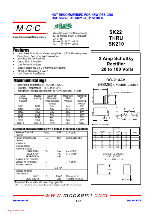
IF(AV) IFSM
VF IR
2.0A 50A
TJ = 90°C 8.3ms, half sine
.55V .70V .85V
IFM = 2.0A; TJ = 25°C*
TJ = 25°C
0.5 mA
Typical Junction
CapacitanceSFra bibliotek22CJ
SK23-SK210
230pF Measured at 50pF 1.0MHz, VR=4.0V
*Pulse test: Pulse width 300 µsec, Duty cycle 2%
Note: 1. High Temperature Solder Exemptions Applied, see EU Directive Annex 7.
SK22 THRU SK210
2 Amp Schottky Rectifier
50 100
Figure 4 New SMB Assembly
.2
.1 0 .2 .4 .6 .8 1.0 1.2 1.4 Volts
Instantaneous Forward Current - Amperesversus Instantaneous Forward Voltage - Volts
Figure 3 Typical Junction Capacitance 10000 6000
Si24R1 2.4G无线收发芯片完整版
应用范围
无线鼠标、键盘 无线遥控、体感设备 有源 RFID、NFC 智能电网、智能家居 无线音频 无线数据传输模块 低功耗自组网无线传感网节点
封装图
15
14
13
12
11
IREF 16
10 XI
VSS 17
9 XO
VCC 18 VDD_D 19
QFN20 4×4
8 VSS 7 VCC
4.2.1 ACK模式 .......................................................................................................... 10 4.2.2 NO ACK模式.................................................................................................... 12 4.2.3 动态PAYLOAD长度与静态PAYLOAD长度................................................ 12 4.2.4 多管道通信...................................................................................................... 12
7.1 极限参数 ................................................................................................................ 22 7.2 电气指标 ................................................................................................................ 22
AZM 170SK-12 00ZRK-2197 24 VAC DC 电子开关机器件说明说明书
DataOrdering dataProduct type descriptionAZM 170SK-12/00ZRK-2197 24 VAC/DC Article number (order number)101183013EAN (European Article Number)4030661318660eCl@ss number, Version 9.027-27-26-03CertificationsCertificates CEcULusCCC EACGeneral dataProduct nameAZM 170Standards EN 60947-5-1BG-GS-ET-19LowActive principleelectromechanical Enclosure materialPlastic, glass-fibre reinforced thermoplastic, self-extinguishing Material of the contacts, electricalSilver Gross weight 357 g AZM170SK-12/00ZRK-2197-24VAC/DCLong lifeCompact designDouble-insulatedHigh holding force90 mm x 84 mm x 30 mmCut clamp terminationThermoplastic enclosure1 Cable entry M 20 x 1.5Manual release from side Interlock with protection against incorrect locking.General data - FeaturesPower to unlock YesManual release YesNumber of actuating directions2Number of auxiliary contacts1Number of safety contacts2Safety appraisalStandards ISO 13849-1Mission Time20 Year(s)Safety appraisal - Safety outputsB10d Normally-closed contact (NC)2,000,000 Operations Mechanical dataMechanical life, minimum1,000,000 Operations Clamping force in accordance with1,000 NISO14119 F zhLatching force30 Npositive break travel11 mmPositive break force, minimum8.5 NActuating speed, maximum 2 m/sMechanical data - Connection techniqueTerminal Connector Screw terminals Cable section, minimum 1 x 0.25 mm²Cable section, maximum 1 x 1.5 mm², flexible Mechanical data - DimensionsHeight of sensor100.5 mmLength of sensor30 mmWidth of sensor108 mmAmbient conditionsProtection class IP 67 to IEC/EN 60529 Ambient temperature, minimum-25 °CAmbient temperature, maximum+60 °CAmbient conditions - Insulation valueRated impulse withstand voltage 4 kVElectrical dataThermal test current 6 A24 VAC/DCRequired rated short-circuit current toEN 60947-5-11,000 AElectrical power consumption,maximum10 WSwitching element NO contact, NC contactNote (Switching element)Change-over contact with double break, type Zb or 2 NC contacts, with galvanically separated contact bridgesSwitching principle Creep circuit element Switching frequency1,000 /hOther dataNote (applications)sliding safety guard removable guard hinged safety guardScope of deliveryIncluded in delivery Actuators must be ordered separately. NotesNote (General)Individual coding available on requestNote (Manual release)rightFor manual release using M5 triangular key, available as accessory Additional manual release on sideOrdering codeProduct type description:AZM 170(1)-(2)Z(3)K(4)-(5)-(6)-(7)(1)without IDC method of termination SK Screw connection(2)11 1 NO contacts/1 NC contact 02 2 NC contactwithout Latching force 5 NR Latching force 30 NI Individual coding(4)without Power to unlockA Power to lock(5)without cable glandST M12 x 1 connectorST-2431Connector M12 x 1, individual solenoid monitoring(6)24VAC/DC Us 24 VAC/DC110VAC Us 110 VAC230VAC Us 230 VAC(7)without Manual release2197Manual release from side (Power to unlock)1637Gold-plated contacts(1)11/11 1 NO contact, 1 NC contact / 1 NO contact 1, NC contact 11/02 1 NO contact, 1 NC contact / 2 NC contacts12/00 1 NO contact, 2 NC contacts / -12/11 1 NO contact, 2 NC contact / 1 NO contact 1, NC contact 12/02 1 NO contact, 2 NC contact / 2 NC contacts02/01 2 NC contacts / 1 NC contact02/10 2 NC contacts, - / 1 NO contact(2)without Latching force 5 NR Latching force 30 N(3)without Power to unlockA Power to lock1637Gold-plated contacts(5)2197Manual release for Power to unlockPicturesProduct picture (catalogue individual photo)ID: kazm1f10| 50,6 kB | .png | 74.083 x 69.85 mm - 210 x 198 Pixel- 72 dpi| 78,9 kB | .jpg | 26.649 x 25.067 mm - 320 x 301 Pixel- 305 dpi| 491,5 kB | .jpg | 243.769 x 229.658 mm - 691 x 651Pixel - 72 dpiDimensional drawing basic componentID: 1azm1g07| 32,7 kB | .jpg | 112.889 x 78.317 mm - 320 x 222Pixel - 72 dpi| 126,8 kB | .jpg | 352.778 x 245.181 mm - 1000 x 695Pixel - 72 dpi| 44,4 kB | .cdr || 10,1 kB | .png | 74.083 x 51.506 mm - 210 x 146Pixel - 72 dpiDiagramID: kazm1k83| 26,4 kB | .jpg | 112.889 x 81.844 mm - 320 x 232Pixel - 72 dpiK.A. Schmersal GmbH & Co. KG, Möddinghofe 3, D-42279 WuppertalThe details and data referred to have been carefully checked. Images may diverge from original. Further technical data can be found in the manual. Technical amendments and errors possible.Generated on 08.07.2020 18:59:01。
SKSCW241RP 24英寸集成门型葡萄酒冷藏室产品说明说明书
SKSCW241RP24-INCH INTEGRATED COLUMN WINE REFRIGERATORStyleDoor StylePanel ReadyDoor SwingReversible (Ships Right Hinge)Interior Cabinet Finish MetalInnovationWiFi-Enabled for ThinQ® Control with iPhone / Android App Yes Remote OperationsYesInstaView™ Window (Knock Twice to See Inside)Yes Wine Cave Technology™Yes Inverter Linear Compressor YesPerformanceTemperature Zones 3Operating Temperatures41° to 64° FHumidity ControlYesModesSabbath, Demo, Power On / Off, Temp Control,Smart Diagnosis, WiFi High Altitude Compatibility YesCapacity and Storage Bottle Capacity (750 ml)113Storage Shelves 11Shelf MaterialBeech Wood with Metal Accents Presenter Shelf2WINE CAVE TECHNOLOGY™Carefully tailored to mimic the ideal environment of historic wine caves, our exclusive design minimizes temperature fluctuations, reduces vibration, limits light passing through, and locks in humidity.PRECISE PRESERVATIONIngenious features like an Inverter Linear Compressor and metal interior help to keep your collection cool whilemaintaining the lowest temperature fluctuation among leading brands* and vibration minimized to less than 2 gal (cm/s 2).LIGHT AND HUMIDITY CONTROLDark-tinted, triple pane glass protects wine from damaging UV light while humidity control boosts humidity to optimum levels, helping to preserve quality and taste.INDEPENDENT TEMPERATURE ZONESThree Independent temperature zones keep sparkling, white, and red wines at the right temperature to bring out the very best taste.TOUCH DISPLAY LIGHTINGShowcase an entire collection with a touch of the door. LED lights are activated by gently tapping the door or with the mobile app. Choose from four display settings including, Presentation, Upper, Lower, and All.SIGNATURE FIT™ INTEGRATED DESIGNEvery integrated column features an intelligent, symmetrical design that allows for flush installation, along with easy door reversal.ECO FRIENDLYEngineered to reduce environmental impact withHFC / HCFC free refrigerant, insulation and recyclable materials, while using just 270 kWh/yr — the lowest energy consumption in the industry.*© 2020 Signature Kitchen Suite. All rights reserved. Design, features and specifications are subject to change without notice. Specifications are for planning purposes only. Consult the product’s installation instructions for final dimensional data and other details prior to making cutouts or custom panels. Consult with a heating and ventilation engineer for your specific ventilation requirements. Non-metric weights and measurements are approximate. Smart features require Internet access. 1-855-790-6655 | * W hen compared to leading brand wine refrigerators of similar size andcapacity as of Feb. 2019.*These warranties give you specific legal rights and you may have other rights that vary from state to state. For complete warranty details, refer to your Use & Care manual. SKSCW241RP24-INCH INTEGRATED COLUMN WINE REFRIGERATORDimensions and Weight Overall Width (inches)23 3/4"Overall Height (inches)83 1/2" Min. – 84 1/2" Max.Overall Depth Without Panel or Handles (inches)23 7/8"Net Weight (approx.)357 lbs.Shipping Weight (approx.)401 lbs.Optional AccessoriesStainless Steel Panel / Handle / Toekick KitSKSWK245RS (Right Hinge, Left Handle)SKSWK245LS (Left hinge, Right Handle)Joining Kit for Dual Column Installation SKSFJ800P Retrofit Frame KitSKSFK800CS Brushed Aluminum Handle Medium – 31 11/16"SKSHK310HSLong – 48" (For Columns)SKSHK480HSWarranty Summary*Limited Warranty, Parts & Labor3 Years Limited Warranty on Sealed System, Parts and Labor5 YearsLimited Warranty on Sealed System, Parts Only10 YearsGeneral FeaturesDigital Touch Controls w/White LED DisplayYes Hidden LED Interior Lighting Yes Presenter Shelf Lighting Yes Maximum Sound Level38 dBAStar-K Certified Sabbath Mode Yes Installation FeaturesFour Point Front Adjustable with 8 WheelsYesAttachment Method to Cabinetry Top with No Visible Screws Front ServiceableYes Anti-tip Bracket Included YesTechnical SpecsRequired Power Supply 115 V, 60 Hz, 15 Amp Plug Type3-Prong Power Cord Length86 1/2"24" (610 mm)finished widthSINGLE COLUMN4"(102 mm)finished return*INSTALLATION CLEARANCES – FLUSH INSTALLATION SKSCW241RP 24-INCH INTEGRATED COLUMN WINE REFRIGERATORthickness of the custom cabinet panel. The door panels in the optional Signature Kitchen Suite stainless steel door panel kit are 3/4" (19 mm) thick.Door handle must be added to this dimension.1 3/8"(35 mm)A minimum 4"(102 mm) finished return that matches the cabinet exterior is recommended on all sides and the top of the cutout opening. The shaded area will be visible after installation.*5"(127 mm)electrical location25" (635 mm)min. depth84"(2134 mm)CUTOUT DIMENSIONS – FLUSH INSTALLATION NotesWine refrigerator can be installed flush with 3/4" custom panel or optional stainless steel panel kit.With a 25" (635 mm) cutout depth, the front face of the wine refrigerator fits flush with 25" (635 mm) depth adjacent cabinets.Electrical A 115V, 60Hz., 15 amp power supply is required. An individual properly grounded branch circuit or circuit breaker is recommended. Install a properly grounded 3-prong electrical receptacle recessed into the back wall.Electrical must be located on rear wall as shown.Note : GFI (ground fault interrupter) is not recommended.SINGLE COLUMN Notes Door Swing Clearances – The installation must allowfor clearances to adjacent walls or cabinets. This wine refrigerator is equipped with a 2-position door stop. The factory-set 115° door swing can be adjusted to 90° if clearance to adjacent cabinets or walls is restricted.Door Handle Clearances – The Door Handle depth must be added to the dimension noted to determine the total clearances required from adjacent cabinets or walls. This clearance will vary depending on the custom handle used. When using the Stainless Steel Door Panel Kit w/Handle or the Brushed Aluminum Handle (optional accessories), the door handle clearance with door open 115° is 14" INSTALLATION CLEARANCES – FLUSH INSTALLATION TOP VIEW CUTOUT DIMENSIONS – FLUSH INSTALLATIONSINGLE COLUMN 4"(102 mm)finished return*TOP VIEW INSTALLATION CLEARANCES – FLUSH INSTALLATION SKSCW241RP 24-INCH INTEGRATED COLUMN WINE REFRIGERATOR Varies depending on the thickness of the custom cabinet panel. The door panels in the optional Signature Kitchen Suite stainless steel door panel kit are 3/4" (19 mm) thick. Door handle must beadded to this dimension.(35 mm)A minimum 4" (102 mm) finished return that matches the cabinet exterior is recommended on all sides and the top of the cutout opening. The shaded area will be visible after installation.*3/4"(19 mm)**.location 25" (635 mm)min. depth 84"(2134 mm)SKSCW241RP 24-INCH INTEGRATED COLUMN WINE REFRIGERATOR24 3/4"*22"***23 7/8"**(629 mm)(558 mm)(607 mm)4"5"(127 mm)(102 mm)Depth with 3/4"(19 mm) door panel Depth with door (no panel)Unit depth without door****** 9"(229 mm)3/4"(19 mm)80 9/16"(2046 mm)min.81 9/16"(2072 mm)max.23 3/4"(603 mm)83 1/2"(2121 mm)min.84 1/2"(2146 mm)max.Unit widthwithout door panel FRONT VIEWOVERALL PRODUCT DIMENSIONSSIDE VIEW23 3/4" (603 mm)23 3/4" (603 mm)28 1/8"(713 mm)Unit width withoutdoor panel TOP VIEWDOOR OPEN 90˚Unit width withoutdoor panel TOP VIEWDOOR OPEN 115˚(659 mm)26 1/2"SKSCW241RP 24-INCH INTEGRATED COLUMN WINE REFRIGERATOR 22"***23 7/8"**(629 mm)(558 mm)(607 mm)4"5"(127 mm)(102 mm)Depth with 3/4"(19 mm)door panel Depth with door (no panel)Unit depth without door****** 9" (229 mm)3/4"(19 mm)80 9/16"(2046 mm)min.81 9/16"(2072 mm)max.23 3/4"(603 mm)83 1/2"(2121 mm)min.84 1/2"(2146 mm)max.Unit width without door panelFRONT VIEWOVERALL PRODUCT DIMENSIONS SIDE VIEW23 3/4"(603 mm)23 3/4"(603 mm)28 1/8"(713 mm)Unit width without door panel DOOR OPEN 90˚Unit width without door panelDOOR OPEN 115˚(659 mm)26 1/2"24-INCH INTEGRATED COLUMN WINE REFRIGERATOROVERALL PRODUCT DIMENSIONS TOP VIEWFRONT VIEW DOOR OPEN 90°SIDE VIEWDOOR OPEN 115°SKSCW241RP24-INCH INTEGRATED COLUMN WINE REFRIGERATOR24-INCH INTEGRATED COLUMN WINE REFRIGERATOROPTIONAL ACCESSORIESOPTIONAL ACCESSORIESCUSTOM PANEL DIMENSIONS18" INTEGRATEDWINE COLUMN CUSTOM PANEL DIMENSIONS – FLUSH INSTALLATION79 7/8"(2029 mm)9 3/8"(238mm)7 1/16"(179.5 mm)(603 mm)23 3/4"3 3/16"(81 mm)3 3/16"(81 mm)4" (102 mm)Notes These units are designed to be customized with decorative panels. Field-installed custom door panels or an optional Stainless Steel Panel Kit is required.For Custom Panels: Use templates provided with units to pre-drill holes for mounting panel brackets (provided with unit). Adjustment screws and instructions also provided with units.Maximum Total Door Panel Weights: 24-Inch Integrated Column – 22 lbs.18-Inch Integrated Column – 21 lbs.Design Tips4" (102 mm) will be visible on the interior sides of the furniture return. It is recommended that both sides of each cutout panel be finished to match the cabinet exterior.If using custom panels, a custom toe kick is required. The bottom of case is unfinished.Door Handles: Handles are not included with the units. Custom handles are required for installation. Brushed Aluminum Handles are available as an optional accessory.Stainless Steel Panel Kit for 24-inch Integrated Column Wine RefrigeratorThis unit can be installed with an optional Stainless Steel Panel Kit. Kit includes one door panel, one toekick and one handle. Order right or left hinge option, depending on desired installation.SKSWK245RS – 24" Wine Column Stainless Kit, Right Hinge(Horizontal brushed hairlines for right hinge installation, opening from left to right)SKSWK245LS – 24" Wine Column Stainless Kit, Left Hinge(Horizontal brushed hairlines for left hinge installation, opening from right to left)Handles for Use with Custom PanelsSKSHK310HS – 31 11/16" (805 mm) Medium Handle – Brushed Aluminum SKSHK480HS – 48" (1219 mm) Long Handle – Brushed Aluminum Joining Kit for Dual / Multiple Column InstallationSKSFJ800P – This kit is required for installation when a wine column is installed with another wine column, refrigerator column or French door column. This kit is included with all freezer columns.SKSCW241RP24-INCH INTEGRATED COLUMNWINE REFRIGERATOR。
KST24中文资料
KST24NPN Epitaxial Silicon TransistorAbsolute Maximum Ratings T a =25°C unless otherwise noted• Refer to KSP24 for graphsElectrical Characteristics T a =25°C unless otherwise noted* Pulse Test: PW ≤300µs, Duty Cycle ≤2%Symbol ParameterValue Units V CBO Collector-Base Voltage 40V V CEO Collector-Emitter Voltage 30V V EBO Emitter-Base Voltage 4V I C Collector Current100mA P C Collector Power Dissipation 350mW T STG Storage Temperature150°C R TH (j-a)Thermal Resistance Junction to Ambient357°C/WSymbol ParameterTest Condition Min.Typ.Max.Units BV CBO Collector-Base Breakdown Voltage I C =100µA, I E =040V BV CEO Collector-Emitter Breakdown Voltage I C =1mA, I B =030V BV EBO Emitter-Base Breakdown Voltage I E =10µA, I C =04V I CBO Collector Cut-off Current V CB =15V, I E =050nAh FE DC Current GainV CE =10V, I C =8mA 30f T * Current Gain Bandwidth Product V CE =10V, I C =8mA f=100MHz400620MHz C ob Output CapacitanceV CB =10V, I E =0, f=1MHz 0.250.36pF G GConversion Gain (213MHz to 45MHz)(60MHz to 45MHz)I C =8mA, V CC =20VOscillator Injection=150mV19242429dB dBKST24VHF Mixer Transistor3AMarking1. Base2. Emitter3. CollectorSOT-23123KST24TRADEMARKSThe following are registered and unregistered trademarks Fairchild Semiconductor owns or is authorized to use and is not intended to be an exhaustive list of all such trademarks.DISCLAIMERFAIRCHILD SEMICONDUCTOR RESERVES THE RIGHT TO MAKE CHANGES WITHOUT FURTHER NOTICE TO ANY PRODUCTS HEREIN TO IMPROVE RELIABILITY, FUNCTION OR DESIGN. FAIRCHILD DOES NOT ASSUME ANY LIABILITY ARISING OUT OF THE APPLICATION OR USE OF ANY PRODUCT OR CIRCUIT DESCRIBED HEREIN;NEITHER DOES IT CONVEY ANY LICENSE UNDER ITS PATENT RIGHTS, NOR THE RIGHTS OF OTHERS.LIFE SUPPORT POLICYFAIRCHILD’S PRODUCTS ARE NOT AUTHORIZED FOR USE AS CRITICAL COMPONENTS IN LIFE SUPPORT DEVICES OR SYSTEMS WITHOUT THE EXPRESS WRITTEN APPROVAL OF FAIRCHILD SEMICONDUCTOR CORPORATION.As used herein:1. Life support devices or systems are devices or systems which, (a) are intended for surgical implant into the body,or (b) support or sustain life, or (c) whose failure to perform when properly used in accordance with instructions for use provided in the labeling, can be reasonably expected to result in significant injury to the user.2. A critical component is any component of a life support device or system whose failure to perform can be reasonably expected to cause the failure of the life support device or system, or to affect its safety or effectiveness.PRODUCT STATUS DEFINITIONS Definition of TermsDatasheet Identification Product Status DefinitionAdvance InformationFormative or In Design This datasheet contains the design specifications for product development. Specifications may change in any manner without notice.PreliminaryFirst ProductionThis datasheet contains preliminary data, andsupplementary data will be published at a later date.Fairchild Semiconductor reserves the right to make changes at any time without notice in order to improve design.No Identification Needed Full ProductionThis datasheet contains final specifications. Fairchild Semiconductor reserves the right to make changes at any time without notice in order to improve design.Obsolete Not In ProductionThis datasheet contains specifications on a product that has been discontinued by Fairchild semiconductor.The datasheet is printed for reference information only.FACT™FACT Quiet series™FAST ®FASTr™FRFET™GlobalOptoisolator™GTO™HiSeC™I 2C™ImpliedDisconnect™ISOPLANAR™LittleFET™MicroFET™MicroPak™MICROWIRE™MSX™MSXPro™OCX™OCXPro™OPTOLOGIC ®OPTOPLANAR™PACMAN™POP™Power247™PowerTrench ®QFET™QS™QT Optoelectronics™Quiet Series™RapidConfigure™RapidConnect™SILENT SWITCHER ®SMART START™SPM™Stealth™SuperSOT™-3SuperSOT™-6SuperSOT™-8SyncFET™TinyLogic™TruTranslation™UHC™UltraFET ®VCX™ACEx™ActiveArray™Bottomless™CoolFET™CROSSVOLT ™DOME™EcoSPARK™E 2CMOS™EnSigna™Across the board. Around the world.™The Power Franchise™Programmable Active Droop™。
- 1、下载文档前请自行甄别文档内容的完整性,平台不提供额外的编辑、内容补充、找答案等附加服务。
- 2、"仅部分预览"的文档,不可在线预览部分如存在完整性等问题,可反馈申请退款(可完整预览的文档不适用该条件!)。
- 3、如文档侵犯您的权益,请联系客服反馈,我们会尽快为您处理(人工客服工作时间:9:00-18:30)。
SK22 THRU S210
SURFACE MOUNT SCHOTTKY BARRIER RECTIFIER VOLTAGE - 20 to 100 Volts CURRENT - 2.0 Amperes
FEATURES
l Plastic package has Underwriters Laboratory Flammability Classification 94V-O l For surface mounted applications l Low profile package l Built-in strain relief l Metal to silicon rectifier majority carrier conduction
l Low power loss, High efficiency l High current capability, low V F l High surge capacity
l For use in low voltage high frequency inverters,
f ree wheeling, and polarity protection applications l High temperature solderin
g guaranteed: 260¢J /10 seconds at terminals MECHANICAL DA TA
Case: JEDEC DO-214AA molded plastic
Terminals: Solder plated, solderable per MIL-STD-750, Method 2026
Polarity: Color band denotes cathode
Standard packaging: 12mm tape (EIA-481)Weight: 0.003 ounce, 0.093 gram
MAXIMUM RA TINGS AND ELECTRICAL CHARACTERISTICS
Ratings at 25¢J ambient temperature unless otherwise specified.
Resistive or inductive load.
SYMBOLS SK22SK23SK24SK25SK26SK28SK29S210
UNITS Maximum Recurrent Peak Reverse Voltage V RRM
20304050608090100Volts Maximum RMS Voltage V RMS
1421283542566471Volts Maximum DC Blocking Voltage V DC
20304050608090100Volts Maximum Average Forward Rectified Current at T L (See Figure 1)
I (AV) 2.0Amps Peak Forward Surge Current 8.3ms single half sine-wave superimposed on rated load(JEDEC method)I FSM 50.0Amps
Maximum Instantaneous Forward Voltage at 2.0A (Note 1)
V F 0.500.700.85Volts Maximum DC Reverse Current T A =25¢J (Note 1)At Rated DC Blocking Voltage T A =100¢J
I R 0.520.0mA
Maximum Thermal Resistance (Note 2)R £K JL
R £K JA
1775¢J /W Operating Junction Temperature Range T J -50 to +125¢J Storage Temperature Range T STG -50 to +150¢J NOTES:
1. Pulse Test with PW=300£g sec, 2% Duty Cycle.
2. Mounted on P.C.Board with 8.0mm 2
(.013mm thick) copper pad areas.
SMB/DO-214AA
RATING AND CHARACTERISTIC CURVES SK22 THRU S210
LEAD TEMPERATURE, ¢J
INSTANTANEOUS FORW ARD VOLTAGE, VOLTS
Fig. 1-FORWARD CURRENT DERATING CURVE
Fig. 2-TYPICAL INSTANTANEOUS FORWARD
CHARACTERISTICS
REVERSE VOLTAGE VOLTS
Fig. 4-TYPICAL JUNCTION CAPACITANCE
PERCENT OF RATED PEAK REVERSE VOLTAGE, %
Fig. 3-TYPICAL REVERSE CHARACTERISTICS
NUMBER OF CYCLES AT 60Hz
Fig. 5-MAXIMUM NON-REPETITIVE PEAK FORWARD SURGE CURRENT。