SYB12864GV11单页资料-Model
12864中文资料
1 AC5 AC4 AC3 AC2 AC1 AC0 SR=0:AC3—AC0 为 ICON IRAM 地址
72us
电子发烧友 电子技术论坛
设定绘图
00
RAM 地址
1 AC6 AC5 AC4 AC3 AC2 AC1 AC0 设定 CGRAM 地址到地址计数器(AC)
L
L
L
L
L
L
H
功能:清除显示屏幕,把 DDRAM 位址计数器调整为“00H”
2、位址归位
电子发烧友 电子技术论坛
CODE: RW RS DB7 DB6 DB5 DB4 DB3 DB2 DB1 DB0
L
L
L
L
L
L
L
L
H
X
功能:把 DDRAM 位址计数器调整为“00H”,游标回原点,该功能不影响显示 DDRAM
3、位址归位
CODE: RW RS DB7 DB6 DB5 DB4 DB3 DB2 DB1 DB0
L
LLL来自LLL
H I/D S
功能:把 DDRAM 位址计数器调整为“00H”,游标回原点,该功能不影响显示 DDRAM 功能:执 行该命令后,所设置的行将显示在屏幕的第一行。显示起始行是由 Z 地址计数器控制的,该 命令自动将 A0-A5 位地址送入 Z 地址计数器,起始地址可以是 0-63 范围内任意一行。Z 地 址计数器具有循环计数功能,用于显示行扫描同步,当扫描完一行后自动加一。
72us 72us 72us 72us 0us 72us 72us
指令表—2:(RE=1:扩充指令集)
指令
指令码
RS RW DB7 DB6 DB5 DB4 DB3 DB2 DB1 DB0
配套液晶PDF资料 12864G中文说明书

序号 1 2 3 4 5 6 7
内容标题 概述 特点 外形及接口引脚功能 基本原理 技术参数 时序特性 指令功能及硬件接口与编程案例
页码 2 2
3~4 4~5 5~6 6~9 9~23
1
1.概述
12864G 型液晶模块由于使 用方便、显示清晰,广泛应用于各种人机交流面板。 2864G 可以显示 128 列*64 行点阵单色图片,或显示 8 个/行*4 行 16*16 点阵的汉字, 或显示 16 个/行*8 行 8*8 点阵的英文、数字、符号。
9
指令名称
RS
(1)显示开/关
0
(display on/off)
指令表
表 8.
指令码
DB7 DB6 DB5 DB4 DB3 DB2 DB1 DB0
1 0 1 0 1 1 1 0 显示开/关:
1 0:关,1:开
说明
(2)显示初始行设置 0 (Display start line set)
(3)页地址设置
5.技术参数
5.1 最大极限参数(超过极限参数则会损坏液晶模块)
名称
符号
标准值
单位
最小
典型
最大
电路电源
VDD - VSS -0.3
7.0
V
LCD 驱动电压 VDD – V0 VDD - 13.5
VDD + 0.3
V
ห้องสมุดไป่ตู้
静电电压
-
-
100
V
工作温度
-10
+60
℃
储存温度
-20
+70
℃
表 2:最大极限参数
5
LCD12864中文资料.(DOC)

12864LCD液晶显示屏中文资料一、概述带中文字库的128X64是一种具有4位/8位并行、2线或3线串行多种接口方式,内部含有国标一级、二级简体中文字库的点阵图形液晶显示模块;其显示分辨率为128×64, 内置8192个16*16点汉字,和128个16*8点ASCII字符集.利用该模块灵活的接口方式和简单、方便的操作指令,可构成全中文人机交互图形界面。
可以显示8×4行16×16点阵的汉字. 也可完成图形显示.低电压低功耗是其又一显著特点。
由该模块构成的液晶显示方案与同类型的图形点阵液晶显示模块相比,不论硬件电路结构或显示程序都要简洁得多,且该模块的价格也略低于相同点阵的图形液晶模块。
二、基本特性(1)低电源电压(VDD:+3.0--+5.5V)(2)显示分辨率:128×64点(3)内置汉字字库,提供8192个16×16点阵汉字(简繁体可选)(4)内置 128个16×8点阵字符(5)2MHZ时钟频率(6)显示方式:STN、半透、正显(7)驱动方式:1/32DUTY,1/5BIAS(8)视角方向:6点(9)背光方式:侧部高亮白色LED,功耗仅为普通LED的1/5—1/10(10)通讯方式:串行、并口可选(11)内置DC-DC转换电路,无需外加负压(12)无需片选信号,简化软件设计(13)工作温度: 0℃ - +55℃ ,存储温度: -20℃ - +60℃三、模块接口说明*注释1:如在实际应用中仅使用串口通讯模式,可将PSB接固定低电平,也可以将模块上的J8和“GND”用焊锡短接。
*注释2:模块内部接有上电复位电路,因此在不需要经常复位的场合可将该端悬空。
*注释3:如背光和模块共用一个电源,可以将模块上的JA、JK用焊锡短接。
控制器接口信号说明:1、RS,R/W的配合选择决定控制界面的4种模式:2、E信号● 忙标志:BF BF标志提供内部工作情况.BF=1表示模块在进行内部操作,此时模块不接受外部指令和数据.BF=0时,模块为准备状态,随时可接受外部指令和数据.利用STATUS RD 指令,可以将BF读到DB7总线,从而检验模块之工作状态.● 字型产生ROM(CGROM)字型产生ROM(CGROM)提供8192个此触发器是用于模块屏幕显示开和关的控制。
汉昇HS12864B液晶显示模块使用说明书
HS12864B液晶显示模块使用说明书感谢您关注和使用我们的液晶产品。
如果您在使用中有任何疑问,请拨打我们的客户服务热线寻求技术支持和获取相关资料,我们竭诚为您服务。
您可以登录我们的网站了解最新产品信息。
或者您可以在我公司网站的留言簿栏目留下您宝贵的意见。
深圳汉昇实业有限公司SHENZHEN HANSHENG INDUSTRIAL CO.,LTD地址:深圳市南山区西丽镇官龙工业村东区18栋5楼邮编:518055公司主页:联系电话:传真:一、 概述HS12864B 使用KS0108(或其兼容芯片)作为控制器,适配M6800系列时序,具有8位标准数据总线。
可显示各种字符及图形。
每个KS0108拥有64×64位(512字节)的显示RAM ,HS12864B 显示屏上的64×64点,显示RAM 中的数据直接作为显示驱动信号。
HS12864B 具有操作指令简单,低功耗的特点。
HS12864B 采用COB 工艺制作。
说明:HS12864B 有STN 黄绿膜,蓝膜以及FSTN 产品可选,LED 背光有多种颜色可选。
用户还可以根据需要自己选定常温、宽温或者超宽温产品。
二、 外形结构1. 外形图2.114-?2. 主要外形尺寸项 目 标 准 尺 寸单 位模 块 体 积 93.0L ×70.0W ×13.0(max )H mm视 域 70.7×38.8 mm 行 列 点 阵 数 128×64 dots 点 距 离 0.48×0.48 mm 点 大 小0.52×0.52 mm三、 硬件说明1. 接口定义管脚符号电平功能描述1 CS1 L 片选信号1,低有效,对应左半屏64×64点2 CS2 L 片选信号2,低有效,对应右半屏64×64点与CSA,CSB不可同时使用3 VSS 0V 电源地4 VDD 5.0V 供电电源,5.0V5 V0 负压 LCD驱动电压输入端(对比度调节)6 RS H/L 寄存器选择端高:数据寄存器低:命令寄存器7 R/W H/L 读/写信号高:读操作低:写操作8 E H,H->L 使能信号9 ~16 DB0~DB7H/L 数据线17 CSA H 片选信号1,高有效,对应左半屏64×64点18 CSB H 片选信号2,高有效,对应右半屏64×64点与CS1,CS2不可同时使用19 /RST H/L 复位信号,低有效20 V out 负压负压输出端21 LEDA 5.0V 背光正极22 LEDK 0V 背光负极说明:HS12864B有两套片选信号,分别是CS1,CS2和CSA,CSB,分别是低有效和高有效,以适应不同用户的需求。
GB12864DNGBBNUB-V01中文资料
JEWEL HILL ELECTRONIC CO.,LTDJEWEL HILL ELECTRONIC CO.,LTD.SPECIFICATIONS FORLCD MODULEModule No. GB12864DOffice Address: Rm. 518,5/F., 101 Shangbu Industrial District,HuaqiangNorthRoad, Shenzhen, ChinaTEL : (86)-755-83362489 83617492FAX: (86)-755-83286396 83365871E-mail: sales@jhlcd@Website: TABLE OF CONTENTSLCM NUMBER SYSTEM (2)1. GENERAL DESCRIPTION (3)2. FEATURES (3)3. MECHANICAL SPECIFICATION (3)4. MECHANICAL DIMENSION (4)5. MAXIMUM RATINGS (5)6. ELECTRICAL CHARACTERISTICS (5)7. MODULE FUNCTION DESCRIPTION (6)8. ELECTRO-OPTICAL CHARACTERISTICS (12)9. RELIABILITY (16)10. PRECAUTIONS FOR USING LCD MODULES (17)11. USING LCD MODULES (19)12. REVISION HISTORY (21)SAMPLE APPROVED REPORT (22)LCM Number SystemNUMBER OF CHAR. PER LINE F: FSTN; X: OTHER VERSION NUMBER: V00~V99IC TYPE:VIEWING DIRECTION:TEMPERATURE RANGE:BACKLIGHT TYPE:SERIAL NUMBER: A~ZGRAPHIC MODULEs: NUMBER OF COMMONs GRAPHIC MODULEs:NUMBER OF SEGMENTs COB & SMT LCMBACKLIGHT COLOR:CHARACTER MODULEs:CHARACTER MODULEs: NUMBER OF LINE G: REFLECTIVE,NONE BACKLIGHT A: TRANSFLECTIVE, EL BACKLIGHT B: TRANSMISSIVE, EL BACKLIGHT C: TRANSFLECTIVE, LED BACKLIGHT D: TRANSMISSIVE, LED BACKLIGHT E: TRANSFLECTIVE, CCFL BACKLIGHT F: TRANSMISSIVE, CCFL BACKLIGHT A: AMBER; B: BLUE; Y: YELLOW-GREEN R: RED; W: WHITE; O: THER COLOR N: NORMAL TEMPERATURE RANGE U: UPPER(12:00); D: DOWN(6:00)L: LEFT(9:00); R: RIGHT(3:00);A: BONDING IC, WITH CONTROLLER B: BONDING IC, WITHOUT CONTROLLER C: SMT IC, WITH CONTROLLER D: SMT IC, WITHOUT CONTROLLER O: OTHER TYPEW: BLACK-WHITE; O: OTHER G: GRAY; Y: YELLOW-GREEN; B: BLUE; LCD COLOR MODE:N: TN; H: HTN; S: STN LCD TYPE:S: SUPER WIDE TEMPERATURE RANGE W: WIDE TEMPERATURE RANGEM: MIDDLE TEMPERATURE RANGE1. GENERAL DESCRIPTIONThe GB12864D is a 128 x 64 Dots Graphics LCD module. It has a STN panel composed of 128 segments and 64 commons. The LCM can be easily accessed by micro-controller via parallel interface.2. FEATURESTransflective and positiveDisplay ModeSTN(Yellow - Green) moduleDisplay Format Graphic 128 x 64 dotsInput Data 8-bit parallel data input from MPUMultiplexing Ratio 1/64DutyBiasBias 1/9Viewing Direction 6 O’clockBacklight LED3. MECHANICAL SPECIFICATIONItem Specifications Unit Dimensional outline 54.0 x 50.0 x 9.5(max) mmResolution 128segs x 64coms dotsViewing area 43.0(W) x 29.0(H) mmActive area 40.92(W) x 24.92(H) mmDots pitch 0.32 (W)×0.39(H) mmDots size 0.28(W)×0.35(H) mm4. MECHANICAL DIMENSION5. MAXIMUM RATINGSItem Symbol Min Max Unit NoteV DD - V ss -0.3 7.0 V Supply voltage V LCD -0.3 24.0 V Input Voltage V IN -0.3 V DD +0.3 VOperating temperature T OPR -10 +60 Storage temperature T STR -20 +70Humidity --- --- 90 %RH6. ELECTRICAL CHARACTERISTICSItem SymbolCondition Min. Typ. Max. UnitSupply Voltage Logic V DD------ 5.0 --- VH level V IH 0.8V DD --- V DDInput VoltageL levelV IL --- V SS --- 0.2V DDVCurrent Consumption(LCD DRIVER)I DD V DD =5.0V; V LCD =11.0V, T amb =25 ;--- --- 1.0 mALCD Driving Voltage V LCDBias=1/9V LCD =V DD -V EE10.7 11.0 11.3 VCurrent Consumption (With LED BackLight)I LEDV DD =5.0V;V LED =4.2V,T amb =25 ;--- --- 500 mA7. MODULE FUNCTION DESCRIPTION7.1. PIN DESCRIPTIONPin No. Symbol Description1 VSSPower supply for Ground (0V)2 VDDPower supply for positive (5V)3 V oLCD driver voltage regulation pin4 D/IH: Data L: Instruction5 R/WRead/write selection signal, R/W=”H”: Read; R/W=”L”: Write6 ERead/write Enable signal input pin7 DB08 DB19 DB210 DB38-bit bi-directional data bus11 DB412 DB513 DB614 DB715 CS1Chip select 1, High level is active16 CS2Chip select 2, High level is active17 RSTReset signal input pin, Low level is active18 VEEPower supply for negative voltage19 APower supply voltage for backlight positive20 KPower supply voltage for backlight negative7.2 TIMING CHARACTERISTICS1. SYSTEM BUS READ/WRITE CHARACTERISTIC2. DISPLAY CONTROL OUTPUT TIMING3. CLOCK TIMING7.3 CIRCUIT BLOCK DIAGRAM7.4 APPLICATION OF LCMReference circuit7.5 TABLE OF COMMAND8. ELECTRO-OPTICAL CHARACTERISTICSItem Symbol Condition Temp Min Typ. Max UnitsNote10.5 11.2 11.525 10.7 11.0 11.3 LCD driving voltageV LCD = = 050 10.9 10.8 11.7 V NOTE1Rise Time (Tr) --- --- -- Decay Time (Tf)0 --- ---- --- Rise Time (Tr) --- 225 340Decay Time (Tf) 25 --- 240 360Rise Time (Tr) --- --- -- Response TimeDecay Time (Tf)= = 0 50 --- --- --msec NOTE2Contrast Ratio Cr= = 0 255 10 --- --- NOTE4Viewing AngleRange( = 0°)(6”) = 90°(3”) =180°(12”) =270°(9”)(25 ) CR ≥245 35 20 30DegNOTE3z For panel only․Electro-Optical Characteristics Measuring Equipment(DMS501)SystemIllumination (D65)․Note 1. Definition of Driving Voltage( Vlcd) :․Note 3. Definition of Viewing Angle and :․Note 4. Definition of Contrast ratio( CR) :Brightness of Non-selected Segment (B2)Brightness of Selected Segment (B1)CR =V,maxCR,maxDriving VoltageB r i gh t n e s s (%)Brightness Curve forSelected Segment0%=90 =270Viewing Direction 6 O’clock DirectionNormal :9. RELIABILITY9.1. MTBFThe LCD module shall be designed to meet a minimum MTBF value of 50000 hours with normal. (25°C in the room without sunlight)9.2. TESTSNO. ITEM CONDITION CRITERION1 High Temperature Operating 60 120Hrs2 Low Temperature Operating -10 120Hrs3High Temperature/Humidity Non-Operating60 ,90%RH ,120 Hrs4 High TemperatureNon-Operating70 120Hrs5 Low TemperatureNon-Operating-20 120Hrs6 Temperature CyclingNon-Operating-10 (30Min )↔ 60 (30Min)10 CYCLESNo Defect OfOperational Function InRoom Temperature AreAllowable.IDD of LCM inPre-and post-test shouldfollow specificationNotes: Judgments should be mode after exposure in room temperature for two hours.10. PRECAUTIONS FOR USING LCD MODULES10.1. HANDLING PRECAUTIONS(1) The display panel is made of glass. Do not subject it to a mechanical shock or impact by droppingit.(2) If the display panel is damaged and the liquid crystal substance leaks out, be sure not to get any inyour mouth. If the substance contacts your skin or clothes, wash it off using soap and water.(3) Do not apply excessive force to the display surface or the adjoining areas since this may cause thecolor tone to vary.(4) The polarizer covering the display surface of the LCD module is soft and easily scratched. Handlethis polarizer carefully.(5) If the display surface becomes contaminated, breathe on the surface and gently wipe it with a softdry cloth. If it is heavily contaminated, moisten a cloth with one of the following solvents: - Isopropyl alcohol- Ethyl alcohol(6) Solvents other than those above mentioned may damage the polarizer.Especially, do not use the following:- Water- Ketone- Aromatic solvents(7) Extra care to minimize corrosion of the electrode. Water droplets, moisture condensation or acurrent flow in a high-humidity environment accelerates corrosion of the electrode.(8) Install the LCD Module by using the mounting holes. When mounting the LCD Module, makesure it is free of twisting, warping and distortion. In particular, do not forcibly pull or bend the I/Ocable or the backlight cable.(9) Do not attempt to disassemble or process the LCD Module.(10) NC terminal should be open. Do not connect anything.(11) If the logic circuit power is off, do not apply the input signals.(12) To prevent destruction of the elements by static electricity, be careful to maintain an optimumwork environment.- Be sure to ground the body when handling he LCD Module.- Tools required for assembling, such as soldering irons, must be properly grounded.-To reduce the amount of static electricity generated, do not conduct assembling and other workunder dry conditions.-The LCD Module is coated with a film to protect the display surface. Exercise care when peeling off this protective film since static electricity may be generated.10.2. STORAGE CONDITIONSWhen storing, avoid the LCD module to be exposed to direct sunlight of fluorescent lamps. For stability, to keep it away form high temperature and high humidity environment (The best condition is : 23±5°C, 45±20%RH). ESD protection is necessary for long-term storage also.10.3. OTHERSLiquid crystals solidify under low temperature (below the storage temperature range) leading to defective orientation or the generation of air bubbles (black or white). Air bubbles may also be generated if the module is subject to a low temperature.If the LCD Module have been operating for a long time showing the same display patterns the display patterns may remain on the screen as ghost images and a slight contrast irregularity may also appear.A normal operating status can be recovered by suspending use for some time. It should be noted that this phenomenon does not adversely affect performance reliability.To minimize the performance degradation of the LCD Module resulting from destruction caused by static electricity etc. exercise care to avoid holding the following sections when handling the modules.- Exposed area of the printed circuit board.- Terminal electrode sections.11. Using LCD modules11.1 LIQUID CRYSTAL DISPLAY MODULESLCD is composed of glass and polarizer. Pay attention to the following items when handling.(1) Please keep the temperature within specified range for use and storage. Polarization degradation,bubble generation or polarizer peel-off may occur with high temperature and high humidity.(2) Do not touch, push or rub the exposed polarizers with anything harder than a HB pencil lead (glass,tweezers, etc).(3) N-hexane is recommended for cleaning the adhesives used to attach front/rear polarizers andreflectors made of organic substances, which will be damaged by chemicals such as acetone, toluene, toluene, ethanol and isopropyl alcohol.(4) When the display surface becomes dusty, wipe gently with absorbent cotton or other soft materiallike chamois soaked in petroleum ether. Do not scrub hard to avoid damaging the display surface.(5) Wipe off saliva or water drops immediately, contact with water over a long period of time maycause deformation or color fading.(6) Avoid contacting oil and fats.(7) Condensation on the surface and contact with terminals due to cold will damage, stain orpolarizers. After products are tested at low temperature they must be warmed up in a container before coming is contacting with room temperature air.(8) Do not put or attach anything on the display area to avoid leaving marks on.(9) Do not touch the display with bare hands. This will stain the display area and degrade insulationbetween terminals (some cosmetics are determinate to the polarizers).(10)As glass is fragile, it tends to become or chipped during handling especially on the edges. Pleaseavoid dropping or jarring.11.2 INSTALLING LCD MODULEAttend to the following items when installing the LCM.(1) Cover the surface with a transparent protective plate to protect the polarizer and LC cell.(2) When assembling the LCM into other equipment, the spacer to the bit between the LCM and thefitting plate should have enough height to avoid causing stress to the module surface, refer to the individual specifications for measurements. The measurement tolerance should be ±0.1mm.11.3 ELECTRO-STATIC DISCHARGE CONTROLSince this module uses a CMOS LSI, the same careful attention should be paid for electrostatic discharge as for an ordinary CMOS IC.(1) Make certain that you are grounded when handing LCM.(2) Before removing LCM from its packing case or incorporating it into a set, be sure the module andyour body have the same electric potential.(3) When soldering the terminal of LCM, make certain the AC power source for the soldering irondoes not leak.(4) When using an electric screwdriver to attach LCM, the screwdriver should be of groundpotentiality to minimize as much as possible any transmission of electromagnetic waves produced sparks coming from the commutator of the motor.(5) As far as possible, make the electric potential of your work clothes and that of the workbenches tothe ground potential.(6) To reduce the generation of electro-static discharge, be careful that the air in the work is not toodried. A relative humidity of 50%-60% is recommended.11.4 PRECAUTIONS FOR OPERATION(1) Viewing angle varies with the change of liquid crystal driving voltage (Vo). Adjust Vo to showthe best contrast.(2) Driving the LCD in the voltage above the limit will shorten its lifetime.(3) Response time is greatly delayed at temperature below the operating temperature range. However,this does not mean the LCD will be out of the order. It will recover when it returns to the specified temperature range.(4) If the display area is pushed hard during operation, the display will become abnormal. However, itwill return to normal if it is turned off and then on.(5) Condensation on terminals can cause an electrochemical reaction disrupting the terminal circuit.Therefore, this product must be used and stored within the specified condition of 23±5°C, 45±20%RH.(6) When turning the power on, input each signal after the positive/negative voltage becomes stable.11.5 SAFETY(1) It is recommended to crush damaged or unnecessary LCDs into pieces and wash them off withsolvents such as acetone and ethanol, which should later be burned.(2) If any liquid leaks out of a damaged glass cell and comes in contact with the hands, wash offthoroughly with soap and water.12. REVISION HISTORYrecord Date Version Reviseversion 05-01-011.0 Original2.0 Change specification format 05-11-203.0 Change contact mode 06-08-01SAMPLE APPROVED REPORT。
51单片机综合学习系统之12864点阵型液晶显示篇
51单片机综合学习系统之 12864点阵型液晶显示篇大家好,通过以前的学习,我们已经对51单片机综合学习系统的使用方法及学习方式有所了解与熟悉,学会了1602字符型液晶显示的基本知识,体会到了综合学习系统的易用性与易学性,这一期我们将一起学习12864点阵型液晶显示屏的基本原理与使用方法。
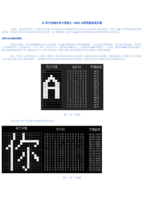
点阵LCD的显示原理在数字电路中,所有的数据都是以0和1保存的,对LCD控制器进行不同的数据操作,可以得到不同的结果。
对于显示英文操作,因为英文字母种类很少,只需要8位<一字节)即可。
而对于中文,常用却有6000以上,于是我们的DOS前辈想了一个办法,就是将ASCII表的高128个很少用到的数值以两个为一组来表示汉字,即汉字的内码。
而剩下的低128位则留给英文字符使用,即英文的内码。
那么,得到了汉字的内码后,还仅是一组数字,那又如何在屏幕上去显示呢?这就涉及到文字的字模,字模虽然也是一组数字,但它的意义却与数字的意义有了根本的变化,它是用数字的各位信息来记载英文或汉字的形状,如英文的'A'在字模的记载方式如图1所示:图1 “A”字模图而中文的“你”在字模中的记载却如图2所示:图2 “你”字模图12864点阵型LCD简介12864是一种图形点阵液晶显示器,它主要由行驱动器/列驱动器及128×64全点阵液晶显示器组成。
可完成图形显示,也可以显示8×4个(16×16点阵>汉字。
管脚号管脚名称LEVER 管脚功能描述1 VSS 0 电源地2 VDD +5.0V 电源电压3 V0 - 液晶显示器驱动电压4 D/I(RS> H/L D/I=“H”,表示DB7∽DB0为显示数据D/I=“L”,表示DB7∽DB0为显示指令数据5 R/W H/L R/W=“H”,E=“H”数据被读到DB7∽DB0R/W=“L”,E=“H→L”数据被写到IR或DR6 E H/L R/W=“L”,E信号下降沿锁存DB7∽DB0R/W=“H”,E=“H”DDRAM数据读到DB7∽DB07 DB0 H/L 数据线8 DB1 H/L 数据线9 DB2 H/L 数据线10 DB3 H/L 数据线11 DB4 H/L 数据线12 DB5 H/L 数据线13 DB6 H/L 数据线14 DB7 H/L 数据线15 CS1 H/L H:选择芯片(右半屏>信号16 CS2 H/L H:选择芯片(左半屏>信号17 RET H/L 复位信号,低电平复位18 VOUT -10V LCD驱动负电压19 LED+ - LED背光板电源20 LED- - LED背光板电源表1:12864LCD的引脚说明在使用12864LCD前先必须了解以下功能器件才能进行编程。
12864中文图形点阵液晶显示模块使用说明书
72us
读出 RAM
的值
1 1 D7
D6
D5
D4
D3
D2
D1
D0
从 内 部 RAM 读 取 数 据 (DDRAM/CGRAM/GDRAM)
72us
指令表 2:(RE=1:扩充指令集)
指令
指令码
RS RW DB7 DB6 DB5 DB4 DB3 DB2 DB1 DB0
说明
执行 时间 (540K HZ)
功能:设定 CGRAM 地址到地址计数器(AC),需确定扩充指令中 SR=0(卷动地址或 RAM 地址选择)
地址
设定 CGRAM 地址到地址计数器(AC)
1 AC5 AC4 AC3 AC2 AC1 AC0 需确定扩充指令中 SR=0(卷动地址或 72us RAM 地址选择)
设定 DDRAM 0 0 1 AC6 AC5 AC4 AC3 AC2 AC1 AC0 设定 DDRAM 地址到地址计数器(AC) 72us
I/O
DB5
I/O
DB6
I/O
DB7
I/O
PSB
I
NC
-
/RST
I
VEE
-
LED+
-
LED-
-
说明
电源地
逻辑电源正(+5V)
LCD 对比度调节电压
并行模式时选择数据或指令
H: 数据 L: 指令
串行模式时选择模块与否
H: 选择 L: 不选择
并行模式时控制读写
H: 读
L: 写
串行模式时输入数据
并行模式时使能端
L
L
L
H
DL
X
RE
X
lx12864d使用手册
Output Voltage
Symbol VDD-VSS
VIL VIH VOH VOL
LCM Recommend LCD Module Driving Voltage
VLCD
Power Supply Current for LCM
IDD(B/L OFF)
Condition -------
Humidity(without condensation)
Note 2,4
Note 3,5
Note 4,5
Note 4,6
Note 2 Ta≦50℃: 80% RH max
Ta>50℃: Absolute humidity must be lower than the humidity of 85%RH at 50℃
--- 0.2VDD Volt
---
---
9.35 9.6 Volt
---
---
--- TBD mA
AC Characteristics System Bus Timing for 6800 Series MPU
Item Address setup time Address hold time System cycle time Enable L pulse width (WRITE) Enable H pulse width (WRITE) Enable L pulse width (READ) Enable H pulse width (READ) Write data setup time Write data hold time Read data access time Read data output disable time
YXD-12864BG LCM规格书
5. 因为液晶材料的物理特性,液晶的对比度会随着温度的变化而相应变化,所以,您加的 负电压值应该随温度作相应的调整,大致是温度变化 10℃ 电压变化 1 伏。为满足这一 要求,您可做一个温度补偿电路,或者安排一个电位器随温度调整负电压值。
线; 9. 长期用于阳光及强光下时被遮部分会产生残留影像;
深圳市烨新达实业有限公司 YXD-12864BG LCM 使用注意事项
版本号:1.0
七、模块的存储
若长期如几年以上存储我们推荐以下方式 1. 装入聚乙稀口袋最好有防静电涂层并将口封住
2. 在-10°C~ +35°C 之间存储
3. 放暗处避强光
显示 8×4 个(16×16 点阵)汉字。
主要技术参数和性能:
1、电源(VDD) :+3.3V或+5V 2、工作电流:约 1.3mA(无背光 4,无负压)4mA(无背光,带负压)底背光电流小于 200mA(5.6Ω限流 电阻) 3、显示内容:128(列)×64(行)点 4、全屏幕点阵 5、七种指令 6、与 CPU 接口采用 8 位数据总线并行输入输出和 6 条控制线 7、占空比(DUTY):1/64 8、工作温度:-10℃~+55℃,存储温度:-20℃~+60℃
DR 是用来寄存数据的,与指令寄存器寄存指令相对应。当 D/I=1 时,在 E 信 号的下降沿作用下,图形显示数据写入 DR,或在 E 信号高电平作用下由 DR 读 到 DB7~DB0 数据总线。DR 和 DDRAM 之间的数据传输是模块内部自动执行的。 3. 忙标志:BF
BF 标志提供内部工作情况。BF=1 表示模块在进行内部操作,此时模块不接受 外部指令和数据。BF=0 时,模块为准备状态,随时可接受外部指令和数据。
12864中文资料
12864中文资料12864中文资料一、OCM12864液晶显示模块概述OCM12864液晶显示模块是128×64点阵型液晶显示模块,可显示各种字符及图形,可与CPU直接接口,具有8位标准数据总线、6条控制线及电源线。
采用KS0107控制IC。
二、最大工作范围1、逻辑工作电压(Vcc):4.5~5.5V2、电源地(GND):0V3、LCD驱动电压(Vee):0~-10V4、输入电压:Vee~Vdd5、工作温度(Ta):0~55℃(常温) / -20~70℃(宽温)6、保存温度(Tstg):-10~65℃三、电气特性(测试条件Ta=25,Vdd=5.0 /-0.25V)1、输入高电平(Vih):3.5Vmin2、输入低电平(Vil):0.55Vmax3、输出高电平(Voh):3.75Vmin4、输出低电平(Vol):1.0Vmax5、工作电流:2.0mAmax四、接口说明12864-1,12864-2接口说明表1 VSS 0V 逻辑电源地。
2 VDD 5.0V 逻辑电源正。
3 V0 LCD驱动电压,应用时在VEE与V0之间加一2K可调电阻。
4 D/I H/L 数据\指令选择:高电平:数据D0-D7将送入显示RAM;低电平:数据D0-D7将送入指令寄存器执行。
5 R/W H/L 读\写选择:高电平:读数据;低电平:写数据。
6 E H.H/L 读写使能,高电平有效,下降沿锁定数据。
7 DB0 H/L 数据输入输出引脚。
8 DB1 H/L 数据输入输出引脚。
9 DB2 H/L 数据输入输出引脚。
10 DB3 H/L 数据输入输出引脚。
11 DB4 H/L 数据输入输出引脚。
12 DB5 H/L 数据输入输出引脚。
13 DB6 H/L 数据输入输出引脚。
14 DB7 H/L 数据输入输出引脚。
15 CS1 H/L 片选择信号,低电平时选择前64列。
16 CS2 H 片选择信号,低电平时选择后64列。