活塞拉杆双用 __ GT5
SMC气缸选型手册

双杆型
CJ2W B 缸径 - 行程
杆不回转型
CJ2K B 缸径 - 行程
低摩擦型
CJ2Q B 缸径 - 行程
行程可调气缸 (伸出可调型)
调程范围:0~15mm
CJ2 B 缸径 - 行程 -XC8
行程可调气缸 (缩回可调型)
调程范围:0~15mm
CJ2 B 缸径 - 行程 -XC9
双行程气缸 (双杆型)
!
CJ1 (ø2.5 ø4)
CJ1B4-20SU4
CJ1B4-15SU4 CJ1B4-10SU4
CJ1B4-5SU4
CJ1B2-5SU4
CJ1B2-10SU4
标准规格
缸径 (mm) 使用流体 最高使用压力 最低使用压力 环境和流体温度 活塞速度 缓冲 行程公差 mm
!
!"#$%&
2.5
4
空气
0.7 MPa
缸径(mm) 2.5
记号 行程
S
5
10
16.5
25.5
Z
5
10
29
38
使用ø4/ø2.5聚氨酯管(TU0425)或 软尼龙管(TS0425)
60 -0.5
缸径(mm)
记号
S
Z
行程
5
10
15
20
5
10
15
20
4
19.5 28.5 37.5 46.5
40
49
58
67
11..011
!(
)
!
CJP (ø6 ø15)
!"=E F
行程 缸径 6 ø6mm 10 ø10mm 16 ø16mm
缓冲 无记号 橡胶缓冲
GTD双作用气动执行器
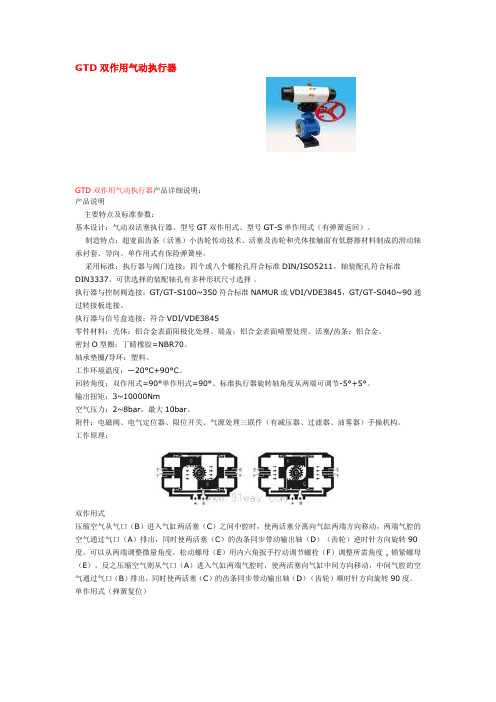
GTD双作用气动执行器GTD双作用气动执行器产品详细说明:产品说明主要特点及标准参数:基本设计:气动双活塞执行器、型号GT双作用式、型号GT-S单作用式(有弹簧返回)。
制造特点:超宽面齿条(活塞)小齿轮传动技术、活塞及齿轮和壳体接触面有低磨擦材料制成的滑动轴承衬套、导向。
单作用式有保险弹簧座。
采用标准:执行器与阀门连接:四个或八个螺栓孔符合标准DIN/ISO5211,轴装配孔符合标准DIN3337。
可供选择的装配轴孔有多种形状尺寸选择。
执行器与控制阀连接:GT/GT-S100~350符合标准NAMUR或VDI/VDE3845,GT/GT-S040~90通过转接板连接。
执行器与信号盒连接:符合VDI/VDE3845零件材料:壳体:铝合金表面阳极化处理。
端盖:铝合金表面喷塑处理。
活塞/齿条:铝合金。
密封O型圈:丁睛橡胶=NBR70。
轴承垫圈/导环:塑料。
工作环境温度:—20°C+90°C。
回转角度:双作用式=90°单作用式=90°、标准执行器旋转轴角度从两端可调节-5°+5°。
输出扭矩:3~10000Nm空气压力:2~8bar,最大10bar。
附件:电磁阀、电气定位器、限位开关、气源处理三联件(有减压器、过滤器、油雾器)手操机构。
工作原理:双作用式压缩空气从气口(B)进入气缸两活塞(C)之间中腔时,使两活塞分离向气缸两端方向移动,两端气腔的空气通过气口(A)排出,同时使两活塞(C)的齿条同步带动输出轴(D)(齿轮)逆时针方向旋转90度。
可以从两端调整微量角度,松动螺母(E)用内六角扳手拧动调节螺栓(F)调整所需角度 , 锁紧螺母(E)。
反之压缩空气则从气口(A)进入气缸两端气腔时,使两活塞向气缸中间方向移动,中间气腔的空气通过气口(B)排出,同时使两活塞(C)的齿条同步带动输出轴(D)(齿轮)顺时针方向旋转90度。
单作用式(弹簧复位)压缩空气从气口(B)进入气缸两活塞(C)之间中腔时,使两活塞分离向气缸两端方向移动,迫使两端的弹簧压缩,两端气腔的空气通过气口(A)排出,同时使两活塞(C)的齿条同步带动输出轴(D)(齿轮)逆时针方向旋转90度。
气缸与磁性开关知识总结
当从无杆腔输入压缩空气时,有杆腔排气,气缸两腔的压力差作用在活塞上所形成 的力克服阻力负载推动活塞运动,使活塞杆伸出;当有杆腔进气,无杆腔排气时,使活 塞杆缩回。若有杆腔和无杆腔交替进气和排气,活塞实现往复直线运动。
1
2
14
3
4
5
6
13 12 11 10 9 8 7
1、3-缓冲柱塞;2-活塞;4-缸筒;5-导向套 ;6-防尘圈;7-前端盖 ;8- 气口 ;9-传感器;10-活塞杆;11-耐磨环;12-密封圈 ;13-后端盖;14-缓冲 节流阀
气缸的原理 ........................................................................................................................ 3 普通气缸 .................................................................................................................... 3 磁性开关气缸的结构和工作原理.....................................................................动作指示灯 ;2-保护电路 ;3-开关外壳;4-导线;5-活塞;6-磁环;7 -缸筒;8-舌簧开关
发动机活塞设计课设说明书
学号:课程设计题目10kW四冲程汽油机活塞组设计学院专业班级姓名指导教师2013 年11 月18 日课程设计任务书学生姓名:专业班级:指导教师:工作单位:题目:10kW四冲程汽油机活塞组设计初始条件:1、平均有效压力:0.8~1.2MPa2、活塞平均速度:<18m/s要求完成的主要任务:1、装配图设计。
2、零件图设计。
3、说明书1份。
时间安排:序号项目应完成时间备注2012.11.121 课题准备1、设计发动机的结构参数。
2、进行运动学计算。
3、形成文档。
武汉理工大学《汽车发动机设计》课程设计说明书2012.11.13 2 装配图设计与绘图1、热力学计算。
2、动力学计算。
3、形成文档。
2012.11.14 3 装配图设计与绘图1、结构参数设计并形成文档。
2、装配图设计绘图(草图)。
4 装配图设计与绘图(底图)2012.11.155 装配图设计与绘图(加粗与标注)2012.11.162012.11.19 6 零件图设计1、零件计算。
2、形成文档。
7 零件图设计绘图2012.11.208 零件图设计绘图2012.11.219 零件图设计绘图2012.11.2210 零件图设计绘图2012.11.2311 零件图设计绘图2012.11.2612 撰写设计说明书2012.11.2713 撰写设计说明书2012.11.2814 答辩2012.11.2915 答辩2012.11.30注意事项:1、课程设计期间必须严格遵守学校的作息时间。
2、指导教师每天点名。
3、学生每天的任务必须完成,指导教师作好相应的进度记录。
指导教师签名:2013年11月18日系主任(或责任教师)签名:年月日武汉理工大学《汽车发动机设计》课程设计说明书目录前言 (1)1汽油机结构形式的设计 (1)1.1汽缸数和气缸布置的选择 (1)1.2冷却方式 (1)2汽油机结构参数的选取 (2)2.1汽缸直径的确定 (2)2.2缸径行程比S/D (3)2.3转速n的确定 (3)2.4汽缸工作容积与升功率 (3)2.5曲柄半径与连杆长度之比λ的选取 (3)2.6缸心距的确定 (3)2.7压缩比与燃烧室容积Vc,总容积Va (3)3热力学计算 (4)3.1燃烧过程数学模型 (4)3.1.1绝热压缩起点 (4)3.1.2绝热压缩过程 (4)3.1.3定容增压过程 (5)3.1.4 绝热膨胀过程 (5)3.2 绘制P-V图 (5)3.2.1绘制理论P-V图 (5)3.2.2 绘制调整P-V图 (6)3.3热力学平均有效压力校核 (7)4运动学计算 (8)4.1活塞位移 (8)4.2活塞瞬时速度 (9)4.3活塞的加速度、最大加速度 (10)5力学计算 (11)5.1气体压力:由P~V图转化为P~α图 (11)5.2往复惯性力 (12)5.3旋转往复惯性力 (12)5.4合力的计算 (13)6活塞设计 (17)6.1活塞的材料 (17)6.2活塞主要尺寸设计 (17)6.2.1活塞高度H (17)6.2.2压缩高度H1 (17)6.2.3火力岸高度h (17)6.2.4环带高度 (17)6.2.5活塞顶部厚度δ (18)6.2.6活塞侧壁厚度及内部过渡圆角 (18)6.2.7活塞销座间距 (18)6.3活塞裙部及其侧表面形状的设计 (19)6.3.1裙部椭圆 (19)6.3.2配缸间隙 (19)6.4活塞头的质量计算 (19)7活塞销的设计 (20)7.1活塞销的材料 (21)7.2活塞销与销座的结构设计 (21)7.3活塞销与销座的配合 (21)7.4活塞销质量m3 (21)7.5活塞销刚度和强度的校核 (22)8活塞环设计 (23)8.1活塞环的密封机理 (23)8.2气环的设计 (24)8.2.1气环的断面形状 (24)8.2.2气环的尺寸参数 (24)8.2.3活塞环的材料 (25)8.3油环的设计 (25)8.4活塞环强度校核 (26)小结 (27)参考文献 (28)附录 (29)10KW四行程汽油机活塞组设计前言这学期我们专业学习了《汽车发动机设计》这门最重要的专业课之一。
PARKER油缸2H系列拉杆缸

派克汉尼汾是全球运动和控制技术行业的领导 者。派克在 1200 个工业和航空航天市场上,提供 800 多个液压、气动和机电产品系列。派克在全球拥有 50000 多名员工、210 个制造工厂和办公点,以能够给 客户提供卓越的技术和一流的服务而著称。
/
凸肩上的场合;当负载并非紧靠在活塞杆端凸肩
上时,推荐使用杆端方式 8。
杆端方式 9 当需要使用杆端内螺纹进行连接时,使用该
杆端方式。
杆端方式 3 方式 3 为非标的杆端方式的代号。订购时,
请附上杆端的图纸或文字说明,并须指明 KK 和 A 的尺寸。
杆端方式 7 方式 7 仅适用于活塞杆端装配带球面轴承的
的速度——见第 B35 页。缸头端的缓冲是自动对中 的,而表面抛光的缸盖端缓冲则是活塞杆的一部 分。
双唇防尘圈起第二道密封作用,能够把多余的润 滑油膜密封在防尘圈与唇形密封件之间的容腔内。其 外唇防止脏物进入缸内,从而延长了 Gland 和密封件 的使用寿命。
8 浮动的缓冲衬套和套筒 缸头端采用浮动的缓冲套筒,缸盖端则采用浮
除非另行注明,所有尺寸单位均为毫米。
1 除 1"-14 的螺纹按 UNS 标准外,其余螺纹按 UNF 标准。 2 方式 7 仅适用于杆端装配带球面轴承的耳环附件的场合,
见第 B29 页。
派克汉尼汾
B3
液压缸部
中国
样本 HY07-1110/CN 贮存、安装和重量
拉杆缸 2H 系列
贮存
当液压缸需要存放在干燥、干净和无腐蚀性气体的室内环境
2. 若液压缸的工作环境中存在可快速干燥的化 学制品、油漆、焊接飞溅物等,或者处于其他 具有危害性的环境中,如过高的温度,则必须 加装防护罩,以防止对液压缸的活塞杆和杆密 封件造成损害。
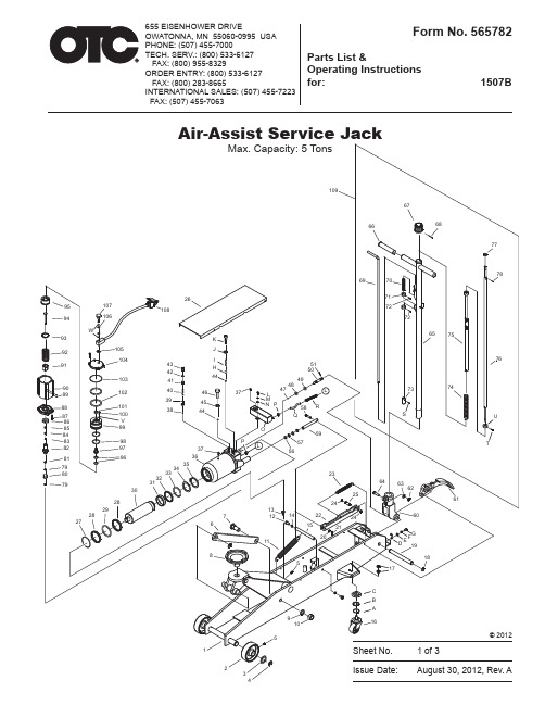
EISENHOWER DRIVE 1507B655 5吨空气助力杆架说明书
92
105
104 91
103
90
89
102
88
101
87
100
86
V
85
99
84
83
98
82
97Leabharlann 819679 80
79 30
28
29 28 27
26 108
K J
I
43 42
H
44
41
40
46
37
39
45
38
44
P 37
36
35 34 33 32 31
7 6
8
51 50
49
48
47
L
M
NP
58
Q
L R
531864 Release Valve Kit 47 1 Steel ball 48 1 O-ring 49 1 O-ring 50 1 Release valve rod 51 1 Pin
Parts List & Operating Instructions
Item No. Qty. Description
565766 Air Motor Seal Kit 28 2 Washer 29 1 O-ring 32 1 Sealing washer 33 1 O-ring 34 1 O-ring retainer 37 2 Oil filler plug 42 1 Sealing washer 45 1 Copper washer 48 1 O-ring 49 1 O-ring 56 2 O-ring 57 2 Washer 79 2 Copper washer 80 1 Oil valve assy 81 1 Nylon gasket 83 1 Oil seal 84 1 Washer 85 1 Copper washer 96 2 O-ring 98 2 O-ring 101 1 Air seal 102 2 O-ring 103 1 O-ring 106 2 O-ring J 1 Copper washer V 3 O-ring W 2 Ring
Cryo S 50 自由活塞斯特林制冷机应用模块 操作手册说明书
Cryo S50自由活塞斯特林制冷机使用本产品前请仔细阅读本操作手册,操作不当可能导致事故,请务必保存本手册。
目录1.产品介绍 (1)1.1.说明 (1)1.2.手册内容 (1)2.安全操作注意事项 (2)2.1.警告 (3)2.2.注意事项 (4)3.Cryo S50的特性 (5)3.1.自由活塞斯特林电机 (5)3.2.温度监控功能 (6)3.3.图形化用户界面 (6)4.拆包和安装 (7)4.1.拆包 (7)4.2.安装 (7)5.操作 (10)5.1.操作注意事项 (10)5.2.操作责任 (10)5.3.用户界面操作指南 (11)5.4.错误/警报和故障排除 (16)6.技术参数 (18)6.1.应用模块规格参数 (18)6.2.Cryo S50制冷机尺寸图纸 (19)6.3.Cryo S50制冷机25℃环境下制冷性能 (19)7.保修范围 (20)1.产品介绍1.1.说明华斯特林Cryo S50自由活塞斯特林制冷机,使用安全环保的氦气作为制冷工质,采用国际先进的自由活塞斯特林技术,其温度范围广,±0.1℃的精准控温,尺寸小,携带方便,非常适用于小型低温运输应用的开发。
本操作手册介绍了华斯特林Cryo S50自由活塞斯特林制冷机的接收,安装,设置,使用和存储的各个方面。
制冷机由用户界面(UI)屏幕控制,本操作手册第5节中介绍了UI的使用。
在二级污染和二级过电压环境中被分类为稳定设备。
该产品设计用于在以下环境条件下运行:●室内使用●海拔2000米●温度高达30°C时的最大相对湿度为80%1.2.手册内容●安全须知●产品特征●安装程序●产品使用●故障排除●技术参数●保修范围注意:安全事项关系到整体的各个部分,须严格遵守以免损坏制冷机或伤害用户。
2.安全操作注意事项使用前,请仔细阅读以下安全须知,以防您和您周围的人受伤或财产受损。
与使用Cryo S 50自由活塞斯特林制冷机相关的潜在危险可能会影响放置制冷机的工作场所人员的安全,制冷机本身也可能因操作或使用不当而损坏和/或其保修失效,所有负责制冷机安装、操作、运输或存放的人员都应阅读本手册以了解这些危害,可考虑将本手册存放在制冷机附近以备参考。
Parker Hannifin 品牌 P5T 系列短杆推进器说明书
P5T SeriesShort Stroke ThrusterContentsFeatures ............................................................................F2Ordering Information .........................................................F3Specifications ....................................................................F4Engineering Data ...............................................................F6Dimensions ......................................................................F14Options ............................................................................F16Sensors ...........................................................................F21A074P5T SeriesFeaturesComposite Bushings or Linear Ball BearingsParker uses a PTFE impregnated composite bushing which serves as a lubrication reservoir. This results in higher load carrying capabilities, both dynamic and static, with excellent resistance to shock loading. The impregnated lubricant also makes the bearings more dirt tolerant. Composite bushings with oversized shafting are available for high impact loads. Optional recirculating ball bearings provide precision opera-tion with very low friction and wear.Internal BumpersAre standard on all units. Theseprovide energy dissipation and noise reduction which result inlonger operating life.Standard Dowel HolesDowel holes on body provide simple, economical and precise mounting.S ensor GroovesAllow reed or solid state s ensor s to be mounted flush to the body. Magnetic piston is standard.Compact, One-Piece BodyProvides economy and minimum package size by integrating a low profile cylinder and support shafts into a single body.Rear PortingRear porting is standard. Optional side porting isavailable.Tooling PlatePrecision machined fromsteel, the tooling plate is thick and rigid to provide a durable connection.Top PortingT op porting is standard. Optional side porting is available.Dowel Holes Standard dowel holes provideprecision mounting and alignment on the tool plate.P5T SeriesA074Bore Size Standard Strokes (mm)* (mm) 10 25 40 50 75 100 125 150 175 20016 ● ● ● ● ● ● 20 ● ● ● ● ● ● 25 ● ● ● ● ● ●32 - 100 ●● ● ● ●●● ●*Consult factory for special stroke lengths.Ordering InformationModel Code and Ordering InformationExample: P5T -J032DHSN100P5T – J 032 D H S N 100StrokeSee table below for standard stroke lengths. Consult factory for special stroke lengths.Shaft/Bearing Type J Composite Bearing,Chrome Plated Shaft (Std)H Ball Bearing, Stainless Steel ShaftC Composite Bearing,Stainless Steel ShaftBore Size 016 16mm 020 20mm 025 25mm 032 32mm 040 40mm 050 50mm 063 63mm 080 80mm 100 100mmPort Location/Mounting D Dowel Holes, Top Ports, Rear Plugged (Std)R Dowel Holes, Rear Ports, Top Plugged (Std)SDowel Holes, Side Ports 1Port StyleH NPTF (Std)G BSPPP Flow Control, BSPP Port, Prestolok Tube (mm) 1F Flow Control, NPTF Port, Prestolok Tube (inch) 1B Flow Control, BSPP 1NFlow Control, NPTF 1SealsS Nitrile (Std)F Fluorocarbon (High T emp)OptionsN None (Std)B High Load Bearings 2A Bumpers, Adjustable Stop Collars (Extend Only) and Dual Tool Plate (Side Ports Rec) 3, 4E Bumpers and AdjustableStop Collars (Extend Only)3G High Load Bearings,Bumpers and Adjustable Stop Collars (Extend Only) 2, 3D Dual Tool Plate 3, 4XSpecialNOTES:1 Cannot combine flow controls, side ports and 25mm stroke.2 Not available with rear mounting and ports.3 Not available with rear port location (R).4 Includes high load bearings as standard.A074P5T SeriesSpecifications Specifications• Maximum operating pressure: 1MPa (10 bar/145 psi) • Operating characteristics: Double acting • Support rod sizes: ∅8 to 35mm • Mounting: Unrestricted• Operating temperature range (cylinder): Nitrile seals (standard) -18° to 74°C (0° to 165°F)Fluorocarbon seals*-18° to 121°C (0° to 250°F)• Filtration requirement: 40 micron, filtered dry air* See Fluorocarbon seal option for high temperature applications.Quick Reference DataModel (Bore Size)Piston Rod (mm)Bushings Support Rods (mm)Piston Bore Ares Non-Rod Side MaxStroke (mm)Theoretical Force Extend @75 PSI (0.5 MPa)Retract @75 PSI (0.5 MPa) mm 2in 2N lb N lb 168 Ball 8200 0.3110010523.677.417.4Composite102000.3110010523.677.417.420 10Ball 103160.4912516436.812327.8Composite123160.4912516436.812327.825 10Ball 124900.7615025457213.548Composite164900.7615025457213.54832 16 Ball 16804 1.252004029330270Composite20804 1.25200402933027040 16 Ball 161257 1.95200628146528123Composite201257 1.9520062814652812350 20 Ball 201964 3.04200982228825192Composite251964 3.0420098222882519263 20 Ball 203117 4.8320015593621492326Composite253117 4.832001559362149232680 25 Ball 2550277.7920025135842268527Composite3050277.792002513584226852710025Ball 30785412.1720039279133574856Composite35785412.1720039279133574856Mounting BoltsBore SizeSocket Head Cap16M5 x .820M5 x .825M6 x 1.032M8 x 1.2540M8 x 1.2550M10 x 1.563M10 x 1.580M12 x 1.75100M14 x 2.0NOTE: When the P5T is used as an impact stopping system,mounting bolt thread engagement should be 1.5 times bolt diameter.ConstructionBody ..........................................Aluminum End Caps ...................................Aluminum Tool Plate ..........................................Steel Piston Rod ........................ Stainless Steel Support Rods ........Steel (Chrome Plated)Rod Bolts ..........................................SteelP5T SeriesA074WeightsUnits with Composite BushingsWeights in kg (lb)Units with Linear Ball BushingsWeights in kg (lb)Standard Stroke (mm)Model10 25 40 50 75 100 125 150 175 200 16 0.35 0.43 0.51 0.57 0.70 0.84 — — — — (0.77) (0.95) (1.13) (1.25) (1.54) (1.84) 20 — 0.76 0.86 0.94 1.11 1.29 1.47 — — — (1.66) (1.90) (2.06) (2.45) (2.85) (3.24) 25 — 1.13 — 1.39 1.65 1.91 2.17 2.43 — — (2.48) (3.05) (3.63) (4.20) (4.77) (5.35) 32 — 1.67 — 2.07 2.46 2.86 3.26 3.65 4.05 4.45(3.68) (4.55) (5.42) (6.29) (7.17) (8.04) (8.91) (9.78) 40 — 2.00 — 2.42 2.84 3.26 3.68 4.10 4.52 4.84 (4.40) (5.32) (6.25) (7.17) (8.10) (9.02) (9.94) (10.65) 50 — 2.63 — 3.22 3.81 4.40 4.99 5.59 6.18 6.77 (5.78) (7.08) (8.38) (9.69) (10.99) (12.29) (13.59) (14.89) 63 — 3.29 — 3.98 4.66 5.34 6.02 6.71 7.39 8.07 (7.24) (8.75) (10.25) (11.75) (13.25) (14.76) (16.26) (17.76) 80 — 6.06 — 7.12 8.18 9.24 10.30 11.36 12.42 13.48 (13.33) (15.66) (18.00) (20.33) (22.66) (24.99) (27.33) (29.66) 100 — 10.69 — 12.03 13.37 14.71 16.05 17.39 18.73 20.08(23.52)(26.47) (29.42) (32.37)(35.32)(38.27)(41.22)(44.17)Standard Stroke (mm)Model10 25 40 50 75 100 125 150 175 200 16 0.32 0.39 0.46 0.51 0.64 0.76 — — — — (0.70) (0.86) (1.02) (1.13) (1.40) (1.67) 20 — 0.70 0.80 0.86 1.03 1.19 1.36 — — — (1.53) (1.75) (1.90) (2.26) (2.62) (2.99) 25 — 0.98 — 1.20 1.43 1.65 1.88 2.11 — — (2.15) (2.64) (3.14) (3.64) (4.14) (4.63) 32 — 1.51 — 1.86 2.21 2.56 2.91 3.27 3.62 3.97 (3.31) (4.09) (4.86) (5.63) (6.41) (7.18) (7.96) (8.73) 40 — 1.82 — 2.20 2.57 2.95 3.32 3.70 4.08 4.45 (4.01) (4.83) (5.66) (6.49) (7.31) (8.14) (8.97) (9.79) 50 — 2.35 — 2.87 3.39 3.92 4.44 4.96 5.48 6.01 (5.17) (6.32) (7.47) (8.62) (9.76) (10.91) (12.06) (13.21) 63 — 2.99 — 3.60 4.22 4.83 5.45 6.06 6.67 7.29 (6.58) (7.93) (9.28) (10.63) (11.98) (13.33) (14.68) (16.03) 80 — 5.66 — 6.63 7.61 8.58 9.56 10.53 11.51 12.49 (12.45) (14.59) (16.74) (18.88) (21.03) (23.18) (25.32) (27.47) 100 — 10.16 — 11.40 12.64 13.89 15.13 16.37 17.61 18.85(22.36)(25.09) (27.82) (30.55)(33.28)(36.01)(38.74)(41.46)dddStandard UnitP5T Series units will have the same load capacity regardless of orientation. The graphs below show maximum load capacity based on a unit life of 10 million cycles .EXAMPLE: A P5T -16 with "stroke + d" of 75mm and composite bushings would have a load capacity of 50N.L o a d ,N (l b )200(45)150(34)100(22)50(11)016mm Bore Size20mm Bore Size25mm Bore SizeL o a d ,N (l b )400(90)300(67)200(45)100(22)010050150200L o a d ,N (l b )500(112)400(90)300(67)200(45)100(22)010050150200010050150200with High Load Bearings and Dual Tool Plate (D, A, B)P5T Series units will have the same load capacity regardless of orientation. The graphs below show maximum load capacity based on a unit life of 10 million cycles.EXAMPLE: A P5T -20 with "stroke + d" of 100mm and high load composite bushings would have a load capacity of 125N.L o a d ,N (l b )200(45)150(34)100(22)50(11)016mm Bore Size20mm Bore Size25mm Bore SizeStroke + d,mm (in)0100(3.9)50(1.9)150(5.9)200(7.9)L o a d ,N (l b )400(90)300(67)200(45)100(22)0Stroke + d,mm (in)0100(3.9)150(5.9)50(1.9)200(7.9)Stroke + d,mm (in)100(3.9)50(1.9)150(5.9)010050150200L o a d ,N (l b )500(112)400(90)300(67)200(45)100(22)063mm Bore Size1005015020080mm Bore Size10050150200L o a d ,N (l b )1500(337)1200(269)900(202)600(135)300(67)0100mm Bore Size200(7.9)dddA074Load Stopping Capacity Standard UnitP5T Series actuators are ideal for conveyor stopping applications. Units can be mounted horizontally or vertically.Composite bushings are strongly recommended for this type of application.EXAMPLE: A P5T -50 unit with a stroke up to 50mm will stop an object moving at 40 cm/second (15.75 in/s) that weighs up to 50 kg (110 lb).NOTE: T he following graphs are based on 50mmof stroke.50mm (1.97")M a s s ,k g (l b )25(55)20(44)15(33)10(22)5(11)0Speed,cm/sec (in/sec))10(3.9)20(7.9)30(11.8)40(15.7)60(23.6)16mm Bore SizeSpeed,cm/sec (in/sec)10(3.9)20(7.9)30(11.8)40(15.7)60(23.6)M a s s ,k g (l b )40(88)30(66)20(44)10(22)020mm Bore SizeM a s s ,k g (l b )80(176)60(132)40(88)20(44)0Speed,cm/sec (in/sec)10(3.9)20(7.9)30(11.8)40(15.7)60(23.6)25mm Bore SizeSpeed,cm/sec (in/sec)10(3.9)20(7.9)30(11.8)40(15.7)60(23.6)M a s s ,k g (l b )200(440)150(330)100(220)50(110)032mm Bore SizeSpeed,cm/sec (in/sec)10(3.9)20(7.9)30(11.8)40(15.7)60(23.6)M a s s ,k g (l b )200(440)150(330)100(220)50(110)040mm Bore SizeSpeed,cm/sec (in/sec)10(3.9)20(7.9)30(11.8)40(15.7)60(23.6)M a s s ,k g (l b )400(880)300(660)200(440)100(220)50mm Bore Size1020304060M a s s ,k g (l b )400(880)300(660)200(440)100(220)63mm Bore Size1020304060M a s s ,k g (l b )600(1320)500(1100)400(880)300(660)200(440)080mm Bore Size1020304060M a s s ,k g (l b )1000(2200)800(1760)600(1320)400(880)200(440)100mm Bore Size50(19.7)50(19.7)50(19.7)50(19.7)50(19.7)50(19.7)5050100(220)50A074Load Stopping Capacity with High Load Bearings and Dual Tool Plate(D, A, B)P5T Series actuators are ideal for conveyor stopping applications. Units can be mounted horizontally or verti-cally.Composite bushings are strongly recommended for this type of application.EXAMPLE: A P5T -25 unit with a stroke up to 50mm will stop an object moving at 40 cm/second (15.7 in/s) that weighs up to 46 kg (101 lb).NOTE: T he following graphs are based on 50mm ofstroke.M a s s ,k g (l b )25(55)20(44)15(33)10(22)5(11)0Speed,cm/sec (in/sec))10(3.9)20(7.9)30(11.8)40(15.7)60(23.6)16mm Bore SizeSpeed,cm/sec (in/sec)10(3.9)20(7.9)30(11.8)40(15.7)60(23.6)M a s s ,k g (l b )40(88)30(66)20(44)10(22)020mm Bore SizeM a s s ,k g (l b )80(176)60(132)40(88)20(44)0Speed,cm/sec (in/sec)10(3.9)20(7.9)30(11.8)40(15.7)60(23.6)25mm Bore SizeSpeed,cm/sec (in/sec)10(3.9)20(7.9)30(11.8)40(15.7)60(23.6)M a s s ,k g (l b )200(440)150(330)100(220)50(110)032mm Bore SizeSpeed,cm/sec (in/sec)10(3.9)20(7.9)30(11.8)40(15.7)60(23.6)M a s s ,k g (l b )200(440)150(330)100(220)50(110)040mm Bore SizeSpeed,cm/sec (in/sec)10(3.9)20(7.9)30(11.8)40(15.7)60(23.6)M a s s ,k g (l b )400(880)300(660)200(440)100(220)50mm Bore Size1020304060M a s s ,k g (l b )400(880)300(660)200(440)100(220)63mm Bore Size1020304060M a s s ,k g (l b )600(1320)500(1100)400(880)300(660)200(440)080mm Bore Size1020304060M a s s ,k g (l b )1000(2200)800(1760)600(1320)400(880)200(440)100mm Bore Size50(19.7)50(19.7)50(19.7)50(19.7)50(19.7)50(19.7)5050100(220)5050mm (1.97")A074Asymmetrical Torque Capacity Standard UnitAsymmetrical loading occurs when the load is applied to one side of the unit. P5T Series units can resist torsional loads that are asymmetrical.EXAMPLE: A mechanism exerts an asymmetrical load of 15Nm on a P5T -50 with 50mm "stroke+d". The P5T -50 with composite bushings will have adequate torsional capacity.T o r q u e ,N m (l b -i n )4(35)3(27)2(18)1(9)016mm Bore Size20mm Bore Size25mm Bore SizeT o r q u e ,N m (l b -i n )16(142)12(106)8(71)4(35)010015050200T o r q u e ,N m (l b -i n )30(266)25(221)20(177)15(133)10(89)0100150502000100150502005(44)A074T o r q u e ,N m (l b -i n )4(35)3(27)2(18)1(9)0Stroke + d,mm (in)0100(3.9)150(5.9)200(7.9)16mm Bore SizeStroke + d,mm (in)0100(3.9)50(1.9)150(5.9)200(7.9)T o r q u e ,N m (l b -i n )6(53)4(35)2(18)20mm Bore SizeT o r q u e ,N m (l b -i n )10(89)8(71)6(53)4(35)2(18)0Stroke + d,mm (in)100(3.9)150(5.9)50(1.9)200(7.9)25mm Bore SizeStroke + d,mm (in)0100(3.9)50(1.9)150(5.9)200(7.9)T o r q u e ,N m (l b -i n )16(142)12(106)8(71)4(35)032mm Bore SizeStroke + d,mm (in)0100(3.9)50(1.9)150(5.9)200(7.9)T o r q u e ,N m (l b -i n )20(177)15(133)10(89)5(44)040mm Bore SizeStroke + d,mm (in)100(3.9)50(1.9)150(5.9)200(7.9)T o r q u e ,N m (l b -i n )25(221)20(177)15(133)10(89)5(44)050mm Bore Size100(3.9)150(5.9)50(1.9)200(7.9)T o r q u e ,N m (l b -i n )30(266)25(221)20(177)15(133)10(89)063mm Bore Size100(3.9)150(5.9)50(1.9)200(7.9)T o r q u e ,N m (l b -i n )80(708)60(531)40(354)20(177)080mm Bore Size100(3.9)150(5.9)50(1.9)200(7.9)T o r q u e ,N m (l b -i n )150(1328)120(1062)90(797)60(531)30(266)100mm Bore Size50(1.9)5(44)Asymmetrical Torque Capacity with High Load Bearings and Dual Tool Plate (D, A, B)Asymmetrical loading occurs when the load is applied to one side of the unit. P5T Series units can resist torsional loads that are asymmetrical.EXAMPLE: A mechanism exerts an asymmetrical load of 15Nm on a P5T -50 with 50mm "stroke+d". The P5T -50 with composite bushings will have adequate torsional capacity.Standard UnitP5T Series units mounted vertically will have the same eccen-tric load capacity regardless of orientation. The graphs provide maximum load capacity for an eccentric mounted load. The load is assumed to be mounted at the face of the tooling plate.These load curves illustrate load ratings based on the bearing system of the product. Load rating is a key selection criterionbut is not the only one to consider in the selection of a product.L o a d ,N (l b )200(45)150(34)100(22)50(11)016mm Bore Size20mm Bore Size25mm Bore SizeL o a d ,N (l b )400(90)300(67)200(45)100(22)0100(3.9)50(1.9)150(5.9)200(7.9)L o a d ,N (l b )500(112)400(90)300(67)200(45)100(22)0100(3.9)50(1.9)150(5.9)200(7.9)100(3.9)50(1.9)150(5.9)200(7.9)y = eccentricity distanceL o a d ,N (l b )200(45)150(34)100(22)50(11)016mm Bore Size20mm Bore Size25mm Bore SizeL o a d ,N (l b )400(90)300(67)200(45)100(22)0100(3.9)50(1.9)150(5.9)200(7.9)L o a d ,N (l b )500(112)400(90)300(67)200(45)100(22)0100(3.9)50(1.9)150(5.9)200(7.9)100(3.9)50(1.9)150(5.9)200(7.9)with High Load Bearings and Dual Tool Plate (D, A, B)P5T Series units mounted vertically will have the same eccen-tric load capacity regardless of orientation. The graphs provide maximum load capacity for an eccentric mounted load. The load is assumed to be mounted at the face of the tooling plate.These load curves illustrate load ratings based on the bearing system of the product. Load rating is a key selection criterion but is not the only one to consider in the selection of a product.y = eccentricity distanceNOTE: On 16mm bore size only, ones ensor groove is available. Whenutilizing two s ensor s on the16mm bore size with 25mmstroke or less, use right angleshort sensors.M odel A** B C D1D2E** F G H J K1637.75 64 31 8 10 10.1 M5/10-3210.1 6.95 22 9.94 (1.49) (2.52) (1.22) (0.315) (0.394) (0.40) (0.40) (0.27) (0.866) (0.39)2036 74 36 10 12 19 1/8 NTPF 10 15.8 26 9.94 (1.42) (2.91) (1.42) (0.394) (0.472) (0.75) OR BSPP (0.39) (0.62) (1.024) (0.39)2538 88 42 12 16 21 1/8 NPTF 11.4 15.5 32 9.94 (1.50) (3.46 (1.65) (0.472) (0.630) (0.83) OR BSPP (0.45) (0.61) (1.260) (0.39)3236 114 51 16 20 10.26 1/8 NTPF 10.35 18.42 38 13.1 (1.42) (4.49) (2.00) (0.630) (0.787) (0.40) OR BSPP (0.41) (0.73) (1.496) (0.52)4044 124 52 16 20 12.10 1/8 NPTF 14.9 22.53 38 13.1 (1.73) (4.88) (2.05) (0.630) (0.787) (0.48) OR BSPP (0.59) (0.89) (1.496) (.052)5044.9 140 62 20 25 14.5 1/4 NTPF 16.1 27 44 14.7 (1.77) (5.51) (2.44) (0.787) (0.984) (0.57) OR BSPP (0.63) (1.06) (1.732) (0.58)6350.05 150 75 20 25 16.4 1/4 NPTF 14.5 33 44 14.7 (1.97) (5.91) (2.95) (0.787) (0.984) (0.65) OR BSPP (0.57) (1.30) (1.732) (0.58)8060.3 188 95 25 30 17.5 3/8 NTPF 19 37 56 18 (2.37) (7.40) (3.74) (0.984) (1.181) (0.610) OR BSPP (0.75) (1.46) (2.205) (0.71)100**67.5 224 115 30 35 21.9 3/8 NPTF 23 40 62 18 (2.60) (8.82) (4.53) (1.181) (1.38) (0.862) OR BSPP (0.91) (1.57) (2.441) (0.71)Model M N P R S T U V W Z AA BB167 7.94 62 25.4 52 16 20 3 6 42 M5 X 7.5 (0.276) (0.31) (2.44) (1.00) (2.047) (.630) (0.787) (0.118) (0.236) (1.654) 0.8 (0.30)2010 7.94 72 31.8 60 18 30 4 6 52 M5 X 7.5 (0.394) (0.31) (2.83) (1.25) (2.362) (.709) (1.181 (0.157) (0.236) (2.047) 0.8 (0.30)2510 7.94 86 38 70 26 34 4 6 62 M6 X 9 (0.394) (0.31) (3.39) (1.50) (2.756) (1.024) (1.339) (0.157) (0.236) (2.441) 1.0 (0.35)325 11.1 112 44.5 96 30 50 6 6 80 M8 X 11 (0.197) (0.44) (4.41) (1.75) (3.780) (1.181) (1.969) (0.236) (0.236) (3.150) 1.25 (0.43)4010 11.1 122 44.5 106 30 60 6 6 90 M8 X 11 (0.394) (0.44) (4.80) (1.75) (4.173) (1.181) (2.362) (0.236) (0.236) (3.543) 1.25 0.43)5010 12.7 138 57.2 120 40 60 8 8 100 M10 X 12 (0.394) (0.50) (5.43) (2.25) (4.724) (1.575) (2.362) (0.315) (0.315) (3.937) 1.5 (0.47)6310 12.7 148 69.9 130 50 72 8 8 110 M10 X 15 (0.394) (0.50) (5.83) (2.75) (5.118) (1.969) (2.835) (0.315) (0.315) (4.331) 1.5 (0.59)8015 16 185 89 160 60 92 10 10 140 M12 X 18 (0.591) (0.63) (7.28) (3.50) (6.299) (2.362) (3.622) (0.394) (0.394) (5.512) 1.75 (0.71)10015 16 221 108 190 80 114 10 10 170 M14 X 21 (0.591) (0.63) (8.70) (4.25) (7.480) (3.150) (4.488) (0.394) (0.394) (6.693) 2.0 (0.83)Model CC DD EE FF GG HH KK LL MM NN PP Piston Rod1610 54 8 27 15 13.06 42 22.5 11.25 9.7 23.0 8 (0.39) (2.126) (0.315) (1.063) (0.591) (0.514) (1.654) (0.88) (0.44) (0.38) (0.91) (0.315)2010 64 10 32 17 13.06 52 26.0 15.4 15.4 26.0 10 (0.39) (2.520) (0.394) (1.260) (0.669) (0.514) (2.126) (1.02) (0.61) (0.61) (1.0) (0.394)2512 76 11 38 21 14.06 62 33.4 17 17 33.4 10 (0.47) (2.992) (0.433) (1.496) (0.827) (0.553) (2.441) (1.31) (0.67) (0.67) (1.31) (0.394)3216 100 14 50 26 12.9 80 42 20 21.7 38 16 (0.63) (3.937) (0.551) (1.969) (1.024) (0.508) (3.150) (1.65) (0.79) (0.85) (1.50) (0.630)4016 110 14 55 26 13.9 90 41 24 26.4 37.9 16 (0.63) (4.33) (0.551) (2.165) (1.024) (0.547) (3.543) (1.61) (0.95) (1.04) (1.49) (0.630)5020 124 16 62 30 14.3 100 51 29 33 44 20 (0.79) (4.882) (0.630) (2.441) (1.181) (0.563) (3.937) (2.01) (1.14) (1.30) (1.73) (0.787)6320 132 18 66 36.5 16.3 110 62 36 37.75 57.75 20 (0.79) (5.197) (0.709) (2.598) (1.437) (0.642) (4.331) (2.44) (1.42) (1.49) (2.27) (0.787)8024 166 22 83 46.5 21 140 78 45 48 75.5 25 (0.94) (6.535) (0.866) (3.268) (1.831) (0.83) (5.512) (3.07) (1.77) (1.89) (2.97) (0.984)10028 200 24 100 56.5 25 170 91.5 53 51 95.5 25 (1.10) (7.874) (0.945) (3.937) (2.224) (0.98) (6.693) (3.60) (2.09) (2.01) (3.76) (0.984)D1With linear ball bearing D2 With composite bushing ** For Model 100 with 25mm stroke, A = 100.3 (3.95") and E = 28 (1.10")A074Shaft BearingsComposite bushings are supplied as standard. Linear ball bearings are optional.Recirculating Ball Bearing (H)Composite Bushing (J,C)Selection should be based on the following criteria:Application Requirement Ball Composite Precision Excellent Good Friction Low Higher Friction coefficient Constant Variable Precision over Constant Variable life of bearing Static Load Capacity Good Excellent Dynamic Load CapacityGood Good with lower efficiencyVibration Resistance Fair Excellent Contamination ResistancePoor ExcellentWashdown CompatibilityPoorExcellentFor bearing load capacities, reference the Engineering Data section.SSTT UU Model mm (in) mm (in) mm (in) F 1624.1 10 20 10-32 (.95)(.39) (.79) or M5 2029.00 10 20 10-32(1.15) (.39) (.79) or M525 35.15 11.4 24 10-32 (1.38) (.45) (.94) or M5 3243.2 10.35 34 1/8 NTPF (1.70) (.41) (1.34) or BSPP 4043.0 14.9 34 1/8 NPTF (1.69) (.59) (1.34) or BSPP 5051.25 16.1 38 1/4 NTPF (2.02) (.64) (1.50) or BSPP 6360.70 15.55 41.8 1/4 NPTF (2.39) (.61) (1.65) or BSPP 8075.5 19 47 3/8 NTPF (2.97) (.75) (1.85) or BSPP 10083.7 23 53.3 3/8 NPTF (3.30) (.91) (2.10) or BSPPSide Porting (S)Corrosion Resistant Shafting (C, H)Chrome-plated case hardened, high carbon alloy steel shaft-ing with composite bearings is utilized for standard slides. This may corrode in some applications. Stainless steel corrosion resistant shafting is available.NOTES:1 Side ports not available on 100mm bore units with 25mm of stroke.2 Cannot use flow controls with 25mm stroke onany bore size.A074Flow Controls (B, F, N, P)Right angle flow control valves allow precise adjustment of cylinder speed by metering exhaust air flow. Prestolok push-in or threaded ports provide 360° orientation capability.Standard abrasion resistant nitrile seals should be used for general purpose applications with temperatures of -18 to 74°C (0 to 165°F). Fluorocarbon seals are recommended for high temperature applications up to 121°C (250°F).Fluorocarbon Seals (F)Feature Temperature Range Bumpers -18 to 93°C (0 to 200°F) Magnets -18 to 74°C (0 to 165°F)S ensor s-10 to 85°C (14 to 185°F)NOTE:When flow controls are specified with rear ports, a 90° right angle fitting is supplied to provide ample rod clearance in the rear.Prestolok flow controls are not available on 32-100mm bore sizes with 25mm of stroke.AB C ImperialModel (in) (in) (in) Prestolok (F) NPT (N) 16, 20*, 25* 0.87 0.96 0.39 5/32" 10-32 20, 25, 32, 40 1.63 1.38 0.67 5/32" 1/8 50, 63 1.86 1.64 0.91 1/4" 1/4 80, 1002.15 1.901.06 3/8" 3/8 A BC Metric Model (mm) (mm) (mm) Prestolok (P) BSPP (B) 16, 20*, 25* 22.0 24.5 10.0 4mm M5 20, 25, 32, 40 34.5 31.6 14.4 6mm 1/8 50 41.0 34.9 18.4 6mm 1/4 63 41.0 41.3 18.4 10mm 1/4 80 51.0 46.7 21.6 10mm 3/8 100 51.0 46.721.6 12mm 3/8* Side ports only.A074Standard Length – No Options (N),* For Model 16 with 10mm stroke, L = 37.7 mm (1.48").** For Model 100 with 25mm stroke, L = 122.8mm (4.8").LModel Stroke (mm) mm inch 1610*, 25, 40, 50, 7560.2 2.37 10075.2 2.96 2025, 40, 50, 75 66.9 2.63 100, 125 91.9 3.62 2525, 50, 75 69.9 2.75 100, 125, 150 91.9 3.62 3225, 50, 75, 100 77.9 3.07 125, 150, 175, 200 116.0 4.57 4025, 50, 75, 100 77.9 3.07 125, 150, 175, 200 116.0 4.57 5025, 50, 75, 100 84.0 3.31 125, 150, 175, 200 124.1 4.89 6325, 50, 75, 100 84.0 3.31 125, 150, 175, 200 124.1 4.89 8025, 50, 75, 100 101.8 4.00125, 150, 175, 200 140.0 5.51 10025**, 50, 75, 100 120.3 4.74125, 150, 175, 200158.46.24High Load Bearings (B)XModel mm inch 16 49.7 1.955 20 47.0 1.849 25 49.9 1.963 32 51.1 2.012 40 59.1 2.327 50 61.6 2.425 63 66.8 2.630 80 79.6 3.135 10086.13.391The standard bearing configuration locates both sets of bearings at the tooling plate end of the actuator providing a compact actuator package. The high load bearings option (B) locates the bearings at the extreme ends of the housing, increasing the dynamic and static load capacity. The bear-ing centerlines increase as stroke length increases.NOTE: Rear mounting and ports are not available with the high load bearing option.DimensionsStandard BearingsA074RodXModel Dia. D option A option E option QQ RR XX 16 8 57.7 70.7 62.7 18.0 15.7 0(2.27) (2.78) (2.47) (0.71) (0.62) 10 57.7 70.7 62.7 24.0 15.7 1 (2.27) (2.78) (2.47) (0.95) (0.62) (0.04) 20 10 54.7 67.9 59.9 24.0 15.7 1(2.15) (2.67) (2.36) (0.95) (0.62) (0.04) 12 54.7 72.6 64.6 28.0 17.7 3 (2.15) (2.86) (2.54) (1.10) (0.70) (0.12) 25 12 58.8 76.5 68.1 28.0 17.7 1(2.31) (3.01) (2.68) (1.10) (0.70) (0.04) 16 58.8 78.5 70.1 34.0 19.7 4 (2.31) (3.09) (2.76) (1.34) (0.78) (0.16)32 16 62.2 81.9 70.8 34.0 19.7 0(2.45) (3.22) (2.79) (1.34) (0.78) 20 62.2 83.9 72.8 40.0 21.7 3.7 (2.45) (3.30) (2.87) (1.57) (0.85) (0.15)40 16 70.2 89.9 78.8 34.0 19.7 0(2.76) (3.54) (3.10) (1.34) (0.78) 20 70.2 91.9 80.8 41.4 21.7 3.7 (2.76) (3.62) (3.18) (1.63) (0.85) (0.15) 50 20 74.3 96.0 83.3 41.4 21.7 0.7(2.93) (3.78) (3.28) (1.63) (0.85) (0.03) 25 74.3 96.0 83.3 45.0 21.7 5.4 (2.93) (3.78) (3.28) (1.77) (0.85) (0.21) 63 20 79.5 101.2 88.5 41.4 21.7 0.7(3.13) (3.98) (3.48) (1.63) (0.85) (0.03) 25 79.5 101.2 88.5 50.8 21.7 5.4 (3.13) (3.98) (3.48) (2.00) (0.85) (0.21) 80 25 96.1 117.8 101.9 50.8 21.7 1.4(3.78) (4.64) (4.01) (2.00) (0.85) (0.06) 30 96.1 117.8 101.9 54.0 21.7 6.3 (3.78) (4.64) (4.01) (2.13) (0.85) (0.25) 100 30 103.3 125.8 109.1 60.5 21.7 3.3(4.07) (4.95) (4.30) (2.38) (0.85) (0.13) 35 103.3 125.8 109.1 57.0 21.7 5.5(4.07) (4.95) (4.30)(2.24) (0.85)(0.22)Bumpers & Adjustable Stop Collars, Extend Only (E)Dual Tool Plate (D)Bumpers, Stop Collars & Dual Tool Plate (A)X + (2 × STROKE)X + (2 × STROKE)QQXXNotes:1. Load capacities increase on dual tool plate (D & A). For load capacities, use the high load bearing graphs.2. Rear mounting holes and rear ports are not available with Options D, A, and E.A074Contaminant & Weld Flash CoversCMODEL AB 10 25 40 50 75 100 125 150 175 200 1642 86 61.2 100.2 135.2 135.2 160.2 200.2 — — — — (1.65) (3.39) (2.41)(3.94) (5.32) (5.32) (6.31) (7.88) 2045 98 — 106.9 141.9 141.9 166.9 216.9 241.9 — — — (1.77) (3.86) (4.21) (5.59)(5.59) (6.57) (8.54) (9.52) 2549 112 — 119.9 — 144.9 169.9 194.9 241.9 266.9 — —(1.93) (4.41) (4.72) (5.70) (6.69) (7.67) (9.52) (10.51) 3262 142 — 127.9 — 152.9 177.9 202.9 266 291 316 341 (2.44) (5.59) (5.04) (6.02) (7.00) (7.99) (10.47) (11.46) (12.44) (13.43) 4062 152 — 127.9 — 152.9 177.9 202.9 266 291 316 341 (2.44) (5.98) (5.04) (6.02) (7.00) (7.99) (10.47) (11.46) (12.44) (13.43) 5066 167 — 134 — 159 184 209 274.1 299.1 324.1 349.1 (2.60) (6.57) (5.28) (6.26) (7.24) (8.23) (10.79) (11.78) (12.76) (13.74) 6377 187 — 134 — 159 184 209 274.1 299.1 324.1 349.1 (3.03) (7.36) (5.28) (6.26) (7.24) (8.23) (10.79) (11.78) (12.76) (13.74) 80104 244 — 151.8 — 176.8 201.8 226.8 290 315 340 365 (4.09) (9.61) (5.98) (6.96) (7.94) (8.93) (11.42) (12.40) (13.39) (14.37) 100109 279 — 170.3 — 195.3 220.3 245.3 308.4 333.4 358.4 383.4(4.29)(10.98)(6.70)(7.69)(8.67)(9.66)(12.14)(13.13)(14.11)(15.09)Weld Flash Cover SpecificationsCoating Material (exposed side) .........................PVC (Black)Base Material .............................................................Nomex Coating Material (other side) ..............................PVC (Black)Material Thickness Range ..................012" - .016" (.3-.4mm)Temperature Resistance (Nomex) Briefly .........................................................642°F (450°C) Continuously .......................-22° to 572°F (-30° to 300°C)T emperature Resistance (Coating) Briefly .........................................................392°F (200°C) Continuously .......................-22° to 302°F (-30° to 150°C)Resistant to ........................Chemicals, coolants, solvents, oil Characteristics .............self-extinguishing, abrasion resistant Material Weight ...............................400 grams/square meterDimensionsA contaminant cover protects the guide rods and bearings from particles and fluid that could cause premature failure.A weld flash cover protects guide rods and bearings from weld spatter.Cover option can be ordered on models having the bearings both ends option. Consult factory to order.BAC。
Parker P3M5H和P6M5H3 16 和3 8 孔5孔硬座管道分压器说明书
Principle of Operation:The 5-valve manifold features 2 isolation valves, 2 equalizer valves and 1 vent valve in a single body for isolation and calibration of differential pressure transmitters. The RADIAL PATTERN™ manifold has an innovative angled bonnet configuration for easy operation. Additional features include a body manufactured from extruded solid bar, robuststems and Parker’s innovative design which ensures a bubble tight seal in a variety of conditions. All Parker valves are manufactured and designed in accordance with MSS-SP105.5 Valve Hard Seat ManifoldsP3M5H ™ and P6M5H ™3/16" and 3/8" Bore 5-Valve Hard Seat ManifoldsSolutions for Oil, Gas, and Petrochemical ProcessingFeatures and Benefits:• Hydrotested at 150% of rated pressure (shell test). Nitrogen gas tested to 2000 psi.Complies with ASME B31.1 & B31.3 shell testing procedures as standard. Ensures structural integrity of valve.• Seat tightness (zero leakage) verified to 110% of rated pressure. Nitrogen gas tested to 2000 psi.Complies with ASME B31.1 & B31.3 seat testing procedures as standard. Ensures zero leakage at seats for proper calibration.• Packing below stem threadPrevents corrosion of critical stem threads• Metal body-to-bonnet seals are in compression, not tension Mitigates risk of stress cracking• Stem threads are rolled, not cutHigher quality stem for longer service life • 8 RMS stem finish Extended packing life • True globe pattern valve Extended packing life• V-Style PTFE packing30-40% less operational torque and less frequent packing adjustments than traditional PTFE packed valves • Pressure component materials sourced from the US, Canada or EuropeReliable material traceability. MTR’s provided with every order for pressure containing components.Parker Hannifin acquired PGI in 2012 and Phoenix Precision Ltd in 2014.The enclosed offering combines the best product features of the acquisitions and isthe best available, safest technology to better serve customers.25 Valve Hard Seat Manifolds • PPL-CAT -P3(6)M5H-001P3M5H ™/P6M5H ™:Pipe x Pipe Technical Specifications3/16" Bore Configuration3/8" Bore Configuration3/8" Bore Configuration3 5 Valve Hard Seat Manifolds • PPL-CAT-P3(6)M5H-0013/8" Bore Configuration45 Valve Hard Seat Manifolds • PPL-CAT-P3(6)M5H-00155 Valve Hard Seat Manifolds • PPL-CAT -P3(6)M5H-001P3M5H ™/P6M5H ™: Stem and Seat Characteristics3/16”Bore O-ring Configuration 3/16”Bore Packed Configuration3/8”PTFE Packed Configuration 3/8”Grafoil™ Packed ConfigurationPressure Core65 Valve Hard Seat Manifolds • PPL-CAT -P3(6)M5H-001P3M3H ™/P6M3H ™: Pressure-Core ®Seal - Advanced Stem Seal SystemA Superior Design for Better Performance:Parker’s patented Pressure-Core ® Stem Seal System was tested by an independent laboratory in accordance with EPA Method 21, and the results indicate that the Pressure-Core ® Stem Seal is a reliable, affordable, virtually leak-free bonnet requiring no costly, time consuming maintenance.After years of field experience and millions of valves in service, Parker takes great pride in extending a five-year limited warranty on our Pressure-Core ® Stem Seal, far exceeding the industry standard.Product Features:• Virtually Leak-Free Performance• No Adjustments or Maintenance Requirements • Unmatched 5 Year Warranty •No Fugitive EmissionsFugitive Emissions Test Results:See for yourself how our Pressure-Core ® not only outperforms the competition, but sets a new industry standard...Test ProcedureValves mechanically cycled 50 times (full open to full close) at 1,000 PSI methane, then heated to 400°F and air cooled to ambient. Procedure repeated until failure.Failure Criteria 100 PPM leak**Competition’s Emission Seal WarrantyTest Results:Parker:The Pressure-Core Seal successfully completed 694 mechanical cycles and 13 thermal cycles. Maximum leakage throughout testing was 40 petition:The competition’s “low emissions” graphite design failed on the 89th mechanical cycle and on average every 125 cycles throughout the testing.Repeated maintenance was required between eachfailure to readjust the valve packing.7006005004003002001000M e c h a n i c a l C y c l e sP3M3H™/P6M3H™: Block Bonnet Characteristics and AccessoriesPTFE and Grafoil™ Packed Bonnet AssemblyMounting Bracket Kit1/2” Socket Weld Adapter1/2” Female Threaded AdapterDust CoverPTFE PackingBack SeatRemovable HandleDust CoverGrafoil™ PackingPTFE Packed Bonnet Grafoil™ Packed BonnetBall Tip StemLocking AdjusterBall Tip StemLocking Adjuster(Lock Pin Not Shown)7 5 Valve Hard Seat Manifolds • PPL-CAT -P3(6)M5H-00185 Valve Hard Seat Manifolds • PPL-CAT -P3(6)M5H-001P3M5H ™/P6M5H ™:Additional Technical InformationMeets the Following Specifications:• ASME B31.1 Power Piping • ASME B31.3 Process Piping• ASME B16.34 Valves - Flanged, Thread, and Welding End • API 598 Valve Inspection and Testing• MSS SP-25 Standard Marking Systems for Valves, Fittings, and Flange Unions • MSS SP-99 Instrument Valves• MSS SP-105 Instrument Valves for Code Applications• NACE MR0175 for all 316SS valves and A105CS body/316SS bonnet (SC Material Code)Material of Construction:Seal and Seat Temperature Rating:Pressure vs. Temperature:Note: Body material specifications based on ASME B16.34 - 2013. Packing material ratings based on manufacturer’s specifications. Approximations only. Parker does not represent these values as finite. They are provided only as representative values.Flow Diagram for all Manifolds:95 Valve Hard Seat Manifolds • PPL-CAT -P3(6)M5H-001P3M5H ™/P6M5H ™:Model Numbering SystemNOTES:105 Valve Hard Seat Manifolds • PPL-CAT-P3(6)M5H-001Parker’s Motion & Control TechnologiesAt Parker, we’re guided by a relentless drive to help our customers become more productive and achieve higher levels of profitability by engineeringthe best systems for their requirements. It means looking at customer applications from many angles to find new ways to create value. Whateverthe motion and control technology need, Parker has the experience, breadth of product and global reach to consistently deliver. No company knows more about motion and control technology than Parker. For further information call 1-800-C-Parker.115 Valve Hard Seat Manifolds • PPL-CAT-P3(6)M5H-001PPL-CAT -P3(6)M5H-001 April2017Parker Hannifin CorporationInstrumentation Products Division 16101 Vallen DriveHouston, TX 77041 USAPhone:(713) 466-0056 • Fax: (713) 744-9892********************|•© 2017 by Parker Hannifin Corporation. All rights reserved. Material in this brochure or catalogue may not be reproduced in whole or in part, in any form, without written permission from the publisher.PEEK is a registered TM of Whitford Wordwide Company and Whitford B.V . KEL-F is a registered TM of M.W. Kellogg Company. GRAFOIL is a registered TM of High Temperature Materials Inc. and Graftech INC. Corporation. AFLAS is a registered TM of Asahi Glass Co. Ltd. Corporation Japan. MONEL and INCONEL are registered TMs of Huntington Alloys Corporation. HASTELLOY is a registered TM of Haynes International, Inc.Parker provides the information herein in good faith but makes no representation as to its comprehensiveness or accuracy. The information contained herein is intended only as a guide to its products and services. Individuals using information must exercise indepen-dent judgment in evaluating product selection and determining product appropriateness for their particular purpose and system requirements. PARKER MAKES NO REPRESENTATIONS OR WARRANTIES, EITHER EXPRESS OR IMPLIED,INCLUDING WITHOUT LIMITATION ANY WARRANTIES OF MERCHANTABILITY OR FITNESS FOR A PARTICULAR PURPOSE WITH RESPECT TO THE INFORMATION SET FORTH HEREIN OR THE PRODUCT(S) TO WHICH THE INFORMATION REFERS. ACCORDINGLY , PARKER WILL NOT BE RESPONSIBLE FOR DAMAGES (OF ANY KIND OR NATURE, INCLUDING INCIDENTAL, INDIRECT, OR CONSEQUENTIAL DAMAGES) RESULTING FROM THE USE OF OR RELIANCE UPON THIS INFORMATION.Patents and Patents Pending in the U.S. and foreign countries. Parker reserves the right to change product designs and specifications without notice.Distributor / Representative:! CAUTION !Do not mix or interchange component parts or tubing with those of other manufacturers. Doing so is unsafe and will void warranty.Parker Autoclave Engineers Valves, Fittings, and Tools are not designed to interface with common commercial instrument tubing and are designed to only connect with tubing manufactured toParker Autoclave Engineers AES specifications. Failure to do so is unsafe and will void warranty.Offer of SaleThe items described in this document are available for sale by Parker Hannifin Corporation, its subsidiaries or its authorized distributors. Any sale contract entered by Parker will begoverned by the provisions stated in Parker's standard terms and conditions of sale (copy available upon request).Parker WorldwideAE – UAE, Dubai Tel: +971 4 8875600********************AR – Argentina, Buenos Aires Tel: +54 3327 44 4129******************AT – Austria, Wiener Neustadt Tel: +43 (0)2622 23501-0*************************AT – Eastern Europe, Wiener NeustadtTel: +43 (0)2622 23501 970****************************AU – Australia, Dandenong Tel: +61 (0)3 9768 5555******************************AZ – Azerbaijan, Baku Tel: +994 50 2233 458****************************BE/LX – Belgium, Nivelles Tel: +32 (0)67 280 900*************************BR – Brazil, Sao Jose dos Campos Tel: +55 12 4009 3504******************BY – Belarus, Minsk Tel: +375 17 209 9399*************************CA – Canada, Grimsby, Ontario Tel +1 905-945-2274*********************CH – Switzerland, Etoy Tel: +41 (0) 21 821 02 30*****************************CL – Chile, Santiago Tel: +56 (0) 2 2303 9640******************CN – China, Shanghai Tel: +86 21 2899 5000*****************************CZ – Czech Republic, Klecany Tel: +420 284 083 111*******************************DE – Germany, Kaarst Tel: +49 (0)2131 4016 0*************************DK – Denmark, Ballerup Tel: +45 43 56 04 00*************************ES – Spain, Madrid Tel: +34 902 33 00 01***********************FI – Finland, VantaaTel: +358 (0)20 753 2500*************************FR – France, Contamine s/Arve Tel: +33 (0)4 50 25 80 25************************GR – Greece, Athens Tel: +30 210 933 6450************************HU – Hungary, Budapest Tel: +36 1 220 4155*************************ID – Indonesia, Tangerang Tel: +62 (0)21 7588 1906********************IE – Ireland, DublinTel: +353 (0)1 466 6370*************************IN – India, MumbaiTel: +91 22 6513 7081-85IT – Italy, Corsico (Ml)Tel: +39 02 45 19 21***********************JP – Japan, Tokyo Tel: +(81) 3 6408 3900******************KR – South Korea, Seoul Tel: +82 2 559 0400*******************KZ – Kazakhstan, Almaty Tel: +7 7272 505 800****************************LV – Latvia, Riga Tel: +371 6 745 2601************************MX – Mexico, Toluca Tel: +52 722 275 4200*******************MY – Malaysia, Selangor Tel: +603 784 90 800*******************NL – The Netherlands, Oldenzaal Tel: +31 (0)541 585 000********************NO – Norway, Stavanger Tel: +47 (0)51 826 300************************NZ – New Zealand, Mt Wellington Tel: +64 9 574 1744PL – Poland, Warsaw Tel: +48 (0)22 573 24 00************************PT – Portugal, Leca da Palmeira Tel: +351 22 999 7360**************************RO – Romania, Bucharest Tel: +40 21 252 1382*************************RU – Russia, Moscow Tel: +7 495 645-2156************************SE – Sweden, Spånga Tel: +46 (0)8 59 79 50 00************************SG – Singapore,Tel: +65 6887 6300*******************SK – Slovakia, Banská Bystrica Tel: +421 484 162 252**************************SL – Slovenia, Novo Mesto Tel: +386 7 337 6650**************************TH – Thailand, Bangkok Tel: +66 2 186 7000*********************TR – Turkey, Istanbul Tel: +90 216 4997081************************TW – Taiwan, Taipei Tel: +886 2 2298 8987*************************UA – Ukraine, Kiev Tel: +380 44 494 2731*************************UK – United Kingdom, Warwick Tel: +44 (0)1926 317878********************USA – IPD, Huntsville Tel: +1 256 881 2040*****************USA – Autoclave Engineers, Erie Tel: +1 814 860 5700*******************VN – Vietnam, Hochi Minh City Tel: +84 (0)8337 546 51**********************ZA – South Africa, Kempton Park Tel: +27 (0)11 961 0700*****************************WARNINGFAILURE, IMPROPER SELECTION OR IMPROPER USE OF THE PRODUCTS AND/OR SYSTEMS DESCRIBED HEREIN OR RELATED ITEMS CAN CAUSE DEATH,PERSONAL INJURY AND PROPERTY DAMAGE.This document and other information from Parker Hannifin Corporation, its subsidiaries and authorized distributors provide product and/or system options for further investigation by users having technical expertise. It is important that you analyze all aspects of your application and review the information concerning the product or system in the current product catalog. Due to the variety of operating conditions and applications for these products or systems, the user, through its own analysis and testing, is solely responsible for making the final selection of the products and systems and assuring that all performance, safety and warning requirements of the application are met. The prod-ucts described herein, including without limitation, product features, specifications, designs, availability and pricing, are subject to change by Parker Hannifin Corporation and its subsidiaries at any time without notice.。
72225 50 25吨空气 水力扩展式地板杆说明书
222385 1
105 Washer
222496 4
106 Screw
222497 4
107 Spring
222498 4
108 Spring Support
222499 1
109 Axle
222501 1
110 Wheel
222390 2
111 Washer
222502 2
112 Retaining Ring
134 Filter
222528 1
135 Screw
222529531 2
137 Handle Tube Bottom Assy. 222530 1
138 Screw
222532 2
139 Washer
222533 4
140 Bushing
222534 2
141 Washer
* Designates parts included in the repair kit
PART REQ'D
NO.
NO.
222360 1 222372 2 222373 2 222374 2 222376 3 222377 3 222378 1 222379 1 222381 1 222382 1 222383 1 222384 1 222386 1 222387 1 222388 1 222389 1 222391 1 222392 1 222393 2 222394 1 222396 1 222397 1 222398 1 222399 1 222401 1 222402 1 222403 2 222406 1 222407 1 222408 1 222409 1 222411 3 222412 1 222413 1 222414 1 222416 1 222417 1 222418 1 222419 2 222421 1 222422 1 222423 1 222424 1 222426 4 222427 8 222428 1 222429 2 222431 2 222432 5 222433 2
- 1、下载文档前请自行甄别文档内容的完整性,平台不提供额外的编辑、内容补充、找答案等附加服务。
- 2、"仅部分预览"的文档,不可在线预览部分如存在完整性等问题,可反馈申请退款(可完整预览的文档不适用该条件!)。
- 3、如文档侵犯您的权益,请联系客服反馈,我们会尽快为您处理(人工客服工作时间:9:00-18:30)。
GT5
GT5 it is a traditional design hydraulic seal set. Grand preload pressure installation is necessary. GT5 是傳統的 V 形組合密封 件,材料是 夾織物,必 須以端蓋預壓安裝。
ROD SEAL (V-PACK SETS) 拉杆 / 活塞雙用封 (V 形疊封)
編 號 Part No. GT5-472393/AI GT5-472393/30 GT5-492393/27 GT5-492393/37 GT5-450400/A GT5-500400/B GT5-511409 GT5-472413 GT5-492413 GT5-511413 GT5-49243321 GT5-511433 GT5-511448 GT5-551452 GT5-531472 GT5-551472/25 GT5-551472/30 GT5-590472 GT5-550475/A GT5-590472 GT5-570492 GT5-590492 GT5-600500/G GT5-590511 GT5-629511 GT5-610531 GT5-629551 GT5-649551/33 GT5-649551/42 GT5-669551/39 GT5-669570 GT5-669590 GT5-708590 GT5-700600/G GT5-716618 GT5-708629 內 徑 d1 100 100 100 100 101.6 101.6 104 105 105 105 110 110 114 115 120 120 120 120 120.65 125 125 125 127 130 130 135 140 140 140 140 145 150 150 152.4 157 160 外 徑 D1 120 120 125 125 114.3 127 130 120 125 130 125 130 130 140 135 140 140 150 139.7 140 150 150 152.4 150 160 155 160 165 165 170 170 170 180 177.8 182 180 槽 寬 L 28 30 27.4 37 26.19 33.32 37 25 29.76 40 21 30 25.8 38 32 25 30 44 28.58 25 27.4 44 38.63 29.75 41.5 30.55 28.5 33 41.95 39 38.1 30.55 40 33.34 30.25 32 編 號 Part No. GT5-748629/33 GT5-748629/47 GT5-767669 GT5-78766945 GT5-787688 GT5-800700/G GT5-826708 GT5-82672824 GT5-866748 GT5-885767 GT5-905787 GT5-90578745 GT5-905787/48 GT5-900800/G GT5-885807 GT5-944826 GT5-1000881 GT5-1003885 GT5-1000900/G GT5-1000900 GT5-1062944 GT5-1102984 GT5-12401102 GT5-12591141 GT5-12991220 GT5-13771240 GT8-13781260/ GT5-141712591 GT5-14371259 GT5-14961338/ GT5-14961338/ GT5-15351377 GT5-15351417 GT5-15741417 GT5-15741452 GT5-19681822 內 徑 d1 160 160 170 170 175 177.8 180 185 190 195 200 200 200 203.2 205 210 224 225 228.6 228.6 240 250 280 290 310 315 320 320 320 340 340 350 360 360 369 463
Power-transmission fluid Material 傳動媒體 主密封材料 NBR Cotton Mineral Oil 礦物油 HFA 5/95 Water base fluid, 夾織物 Water 水基傳動液 / 水 Chamfers & Rad 倒角與圓弧 (mm) 50 90 4 5 0.2 0.2 0.8 0.8
Temperature 溫度範圍℃ -30 - +110 +5 - +60
Speed 速度 ≦ 0.5 m/s
Pressure 工作壓力 400 bar
Max. Gap F 最大擠出間隙 F ≦ 0.2 mm
d1≦ C≧ r1 ≦ r2 ≦
28 4 0.2 0.8
120 6.5 0.2 1.6
140 7.5 0.2 1.6
Tolerance Surface Finishing 表面光潔度 公差 μm Ra μm Rt d1 E8/h9 0.1-0.4 ≦ 4 D1 H10 ≦ 1.6 ≦10 L +0.2 0 ≦ 3.2 ≦16
ROD SEAL (V-PACK SETS) 拉杆 / 活塞雙用封 (V 形疊封)
編 號 Part No. GT5-090050/A GT5-055095 GT5-095062/A GT5-114062 GT5-110075/B GT5-137075/A GT5-118078 GT5-129078 GT5-125187/A GT5-137098 GT5-157098 GT5-150100/B GT5-162100/A GT5-177102 GT5-156106/A GT5-173110 GT5-162112/A GT5-157118 GT5-177118 GT5-196118 GT5-175125/A GT5-177137 GT5-184137 GT5-196137 GT5-204141/B GT5-200150/A GT5-212150/B GT5-212150/C GT5-212150/D GT5-216153 GT5-196157 GT5-216157 GT5-21615726 GT5-220157 GT5-236157/AI GT5-255157 GT5-225175/C GT5-225175/D GT5-226175/A GT5-237175/B GT5-237175/C GT5-250175/A GT5-216177 GT5-236177/AI GT5-236177AI GT5-240177 GT5-255177 GT5-236188 GT5-244188 GT5-2551961 GT5-255196 GT5-275196/B GT5-275196/26 GT5-275196/30 GT5-250200/D GT5-262200/A GT5-262200/B 內 徑 d1 12.7 14 15.87 16 19.05 19.05 20 20 22.22 25 25 25.4 25.4 26 26.98 28 28.57 30 30 30 31.75 35 35 35 36 38.1 38.1 38.1 38.1 39 40 40 40 40 40 40 44.45 44.45 44.45 44.45 44.45 44.45 45 45 45 45 45 48 48 50 50 50 50 50 50.8 50.8 50.8 外 徑 D1 23.01 24 24.13 29 27.94 34.92 30 33 31.75 35 40 38.1 41.27 45 39.67 44 41.27 40 45 50 44.45 45 47 50 52 50.8 53.97 53.97 53.97 55 50 55 55 56 60 65 57.15 57.15 57.5 60.32 60.32 63.5 55 60 60 61 65 60 62 65 65 70 70 70 63.5 66.67 66.67 槽 寬 L 13.49 16 13.49 14.35 16.26 25.4 21.5 14.35 16.69 17.3 17.5 22.22 25.4 29.4 17.65 17.65 19.05 21.8 22.2 27 19.05 21.78 17.5 22.5 17.6 19.05 25.4 26.42 27.38 25.4 17.3 22.6 26 17.63 30 35.75 19.05 20.07 17.29 23.75 27.76 25.4 17.5 22.2 22.2 29 28 25 22.2 22.5 24.6 21.95 26 30 23.11 23.8 25.4 編 號 Part No. GT5-275200/A GT5-300200/B GT5-28420426A GT5-284204/AI GT5-275212/A GT5-263216 GT5-275216 GT5-295216/30 GT5-295216/35 GT5-295216/38 GT5-279220 GT5-299220/20 GT5-299220/22 GT5-275225/A GT5-300225/B GT5-299236/AI GT5-299236AI GT5-303236 GT5-314236/30 GT5-314236/32 GT5-326248 GT5-224248 GT5-300250/A GT5-300250/B GT5-325250/A GT5-325250/B GT6-325250/C GT5-314251 GT5-303255 GT5-314255225 GT5-334255/AI GT5-334255/32 GT5-337262/B GT5-350275/A GT5-350275/C GT5-334275 GT5-354275/B GT5-354275/AI GT5-354295 GT5-374295 GT5-393295 GT5-351300/A GT5-375300/A GT5-374314 GT5-393314 GT5-413314 GT5-400325/A GT5-400350/A GT5-425350/A GT5-450350/A GT5-500350/A GT5-433354/AI GT5-433354AI GT5ห้องสมุดไป่ตู้452354 GT5-452374 GT5-450375/A GT5-452393 內 徑 d1 50.8 50.8 52 52 53.97 55 55 55 55 55 56 56 56 57.15 57.15 60 60 60 60 60 63 63 63.5 63.5 63.5 63.5 63.5 64 65 65 65 65 66.67 69.85 69.85 70 70 70 75 75 75 76.2 76.2 80 80 80 82.55 88.9 88.9 88.9 88.9 90 90 90 95 95.25 100