机器人学导论分析解析
机器人学导论-JohnJCraig - v1

第2章 空间描述和变换
• 2.1 概述 • 2.2 描述:位置、姿态与坐标系 • 2.3 映射:从坐标系到坐标系的变换
• 2.4 算子:平移、旋转和变换
• 2.5 总结和说明 • 2.6 变换算法
• 2.7 变换方程
• 2.8 姿态的其他描述方法 • 2.9 自由矢量的变换
机器人学导论 (美)John.J.Craig
2.2 描述:位置、姿态与坐标系 相关知识:点积
机器人学导论 (美)John.J.Craig
2.2 描述:位置、姿态与坐标系 相关知识:点积
机器人学导论 (美)John.J.Craig
2.2 描述:位置、姿态与坐标系 相关知识:点积
机器人学导论 (美)John.J.Craig
2.2 描述:位置、姿态与坐标系 相关知识:点积
机器人学导论 (美)John.J.Craig 2.1 和姿态两个特性,在数学上就需要定
义坐标系来表达相关参数。
我们定义一个世界坐标系,任何问题都能够参照这个坐标系。位置和姿态都是参照这个世界坐标系或者由世界坐 标系定义的笛卡尔坐标系。
机器人学导论 (美)John.J.Craig
机器人学导论 (美)John.J.Craig
机器人学导论 (美)John.J.Craig
机器人学导论 (美)John.J.Craig
机器人学导论 (美)John.J.Craig
机器人学导论 (美)John.J.Craig
2.2 描述:位置、姿态与坐标系 相关知识:点积
机器人学导论第六章

期望求出期望的关节力矩矢量τ。这个运动 学公式对操作臂控制问题(第10章)很有 用。第二个问题是计算施加在一组关节力 矩的情况下关节如何运动。也就是已知一 个关节矢量τ,计算出操作臂运动的
, 和 。这对操作臂的仿真很有用。
6.2 刚体的加速度
在任一瞬时对刚体的线速度和加速度进行 求导,可分别得到线加速度和量矩阵, V θ,θ是n×1
的离心力和哥氏力矢量, Gθ 是重力矢量。上式
之所以成为状态空间方程,是因为式中 V θ,θ取
决于位置和速度。M θ和 Gθ 中的元素都是关于
操作臂所有关节位置θ的复杂函数,而 V θ,θ中 的
元素都是关于 和的 复杂函数。
可以看出惯性张量是坐标系位姿的函数。众所 周知的平行移轴定理就是在参考坐标系平移是 惯性张量如何变化的计算方法。平行移轴定理 描述了一个以刚体质心为原点的坐标系平移到 另一个坐标系是惯性张量的变换关系。
假设{C}是以刚体质心为原点的坐标系,{A}为任 意平移后的坐标系,则平行移轴定理可表示为
式中 PC xc yczc T 表示刚体质心在坐标系{A}中的位
机器人学导论
第6章 操作臂动力学
第六章 操作臂动力学
6.1概述 到目前为止,我们只研究了操作臂的运动
学。我们已研究了静态位置、静态力和速 度;但是从未考虑引起运动所需的力。在 本章中,将考虑操作臂的运动学方程—— 由驱动器施加的力矩或施加在操作臂上的 外力是操作臂运动。
与 第一操个作臂问动题力,学已有知关一的个两轨个迹问点题 有,待和解决。
计算速度和加速度的向外迭代法
为了计算作用在连杆上的惯性力,需要计算操作 臂每个连杆在某一时刻的角速度、线加速度和角 加速度。首先对连杆1进行计算,由第五章知识
机器人学导论(英) 第三讲
•Point•Vector•Matrix•Calculus•Linear algebra •Dot product •Cross product •Position/Orientation •Rotation matrix •Direction cosine•Coordinate system •Frame•Mapping •Translation •Rotation •Homogeneous transorm •Cross product •Operator •Translational operator •Rotational operator•Transformation operator •Compound transformation •Inverting a transformChapter3 Manipulator Kinematics•What is kinematics ?Kinematics is the sciences of motion that treats the subject without regard to the forces that cause it.•Example:With the knowledge of manipulator’s link length and joint angles, how to compute the position and orientation of the manipulatorsIn kinematics, we consider about the position, the velocity,the acceleration, and the higher derivatives of the position.The study of kinematics refers to all the geometrical and time-based properties of the motion.•Forward kinematicsGiven the joint variables of the robot, determine the position and orientation of the end-effector.[]12...T n θθθΘ=),,,,,(αβγz y x Y =•Kinematic ChainA robot can be treated as a set of right bodies (rigid links) connected together at various joints.•Lower pair:describe the connection between a pair of bodies when relative motion is characterized by two surface sliding over on another.•Joint type (lower pair):1. Revolute2. Prismatic3. Cylindrical4. Planar5. Screw6. Spherical•We consider the joint with 1degree-of-freedom (DOF). A joint with m DOF can be modeled as m joints of 1DOF connected by m-1links of zero length.•The action of joint can be described by a single real number: the angle of rotation in the case of a revolute joint, or the displacement in the case of a prismatic joint.•Number of the links starts from the immobile base (link 0), the first moving body is link 1and so on, out to the freed end of the arm, which is link n .…link1link2link0link6•In kinematics, a link is considered as a rigid body that define the relationship between two neighboring joint axes.1−i a axis i-1axis ilink i-11−i α1−i α:twist angle•Two parameters: link length and link twist angle are used to define the relative location of the two axes.•L ink length: the distance between two axes is measured along a line that is mutually perpendicular to both axes. This line is unique except in the case that two axes are parallel.axis i-1axis ilink i-1a1−ia:link length1−i•Imagine that a plane, whose normal is the mutuallyperpendicular line just constructed, we can project the axis i-1and axis i onto that plane and measure the angle from axis i-1to axis i by the right-hand rule .axis i-1axis ilink n-11−i α:twist angle1−i a•Intermediate links in the chain:Neighboring links has a common joint axis between them. The distance along this common axis from one link to another is defined as “link offset”. It will be variable for prismatic joint.axis i-1axis ilink i-11−iαid1−iaiθiaid:link offset•The angle that rotates about this common axis between one link and its neighboring link is defined as “joint angle ”. It will be variable for revolute joint.axis i-1axis ilink i-11−i αid 1−i a iθia i θ:joint angle•Link length and link twist angle depend on joint axes i and i+1.•For first link in the chain, we set and .00=a 00=α•For last link in the chain, we set and .0=n a 0=n α•If joint 1 is revolute, is set to be 0, zero position ofwill be chosen arbitrarily.1d 1θ•If joint 1 is prismatic, is set to be 0; zero position ofwill be chosen arbitrarily.1θ1d•Link parameters¾For revolute joint, the joint angle is called “joint variable”, and the other three quantities are fixed link parameters.¾For prismatic joint, the link offset is called “jointvariable”, and the other three link quantities are fixed link parameters.θd •Any robot can be described kinematically by giving the values of four quantities for each link, i.e., Denavit-Hartenberg notation[]i i iid a θαvariableconstant• A frame is attached to each link to describe the location of a link relative to its neighbors.•The link frame are named by number according to the link to which they are attached. Step1: frame {i}link {i}link1link2link0link6{0}{1}{2}{6}•Step2: intermediate link in the chain:iZ ˆjoint axis i frame {i}axis i-1axis ilink i-11−i αid 1−i a iθia 1ˆ−i Z 1ˆ−i X 1ˆ−i Y iZ ˆiX ˆiY ˆlink i•Step 3: direction of -along , from joint i to joint i+1iX ˆi a axis i-1axis ilink i-11−i αid 1−i a iθia 1ˆ−i Z 1ˆ−i X 1ˆ−i Y iZ ˆiX ˆiY ˆlink i•Step 4: direction of can be determined by right-hand rule ˆiY•How about if intersect ?is normal to the plane of and .i Z ˆ1ˆ+i Z iX ˆi Z ˆ1ˆ+i Z •First link in the chainsSelection of frame {0} is arbitrarily, will be selected along .0ˆZ 1ˆZ •Last link in the chainsFor revolute joint is chosen along when , the origin of frame {n} is chosen to set . n X ˆ0=n d 1ˆ−n X 0=n θFor prismatic joint, the direction of is chose to make and the origin of {n} is chosen at the intersection of and joint axis n when .0=n θnX ˆ1ˆ−n X 0=n daxis i-1axis ilink i-11−i αid 1−i a iθia 1ˆ−i Z 1ˆ−i X 1ˆ−i Y iZ ˆiX ˆiY ˆlink i•Summary of link parameters: the distance from to measured along : the angle from to measured about : the distance from to measured along : the angle from to measured about iX ˆi a i αi Z ˆ1ˆ+i Z i Z ˆ1ˆ+i Z iX ˆi d i θ1ˆ−i X i X ˆi Z ˆ1ˆ−i X iX ˆi Z ˆ•Summary of link-frame attachment procedure:Step1: identify the join axis (revolute joint/prismatic joint)Step2: identify the common perpendicular between two neighbouring joint axes, at the point of where the common perpendicular meets the i-th axis, assign the link-frame origin. (special case: the two axes intersect)Step3: assign the axis pointing along the i-th joint axis Step4: assign the axis pointing along the common perpendicular (special case: the two axes intersect)iX ˆi Z ˆStep5: assign the axis to complete a right-hand coordinate system.iY ˆStep6: assign the {0} to match {1} when first joint variable is 0.For {n}, chosen origin and directly of freely, but so as to cause as many link parameters as possible to be zero.nX ˆExample 3.3 in the text book(a)(b)Example 3.4 in the text bookwhere two adjacentaxes intersect(a)(b)D-H Tablei1−i a 1−i αid i θ11ˆZ 1ˆX 2ˆZ 2ˆX 3ˆZ 3ˆX 2L Link1Link2Link323D 90000)(2t d 2L )(1t θ)(3t θFrame {0} is coincident with frame {1}.Example 3.5 in the text bookwhere two adjacentaxes intersect•It is possible that there is no unique attachment of frames to link and result in several possible D-H representation.¾There are two choice of direction in which to point .¾In the case of intersecting axes, there are two choices fordirection of . 2ˆZ iX ˆ01=a 901−=α01=d 22L a =02=α12L d =1ˆZ 1ˆX 2ˆZ 2ˆX 3ˆZ 1L 2L case 111()t θθ=22()t θθ=−1=a 901=α01=d 22L a =02=α12L d −=1ˆZ 1ˆX 2ˆZ 2ˆX 3ˆZ 1L 2L case 2•When the direction of is changed, some link parameters willalso be changed. There are four more possible assignments offrames with pointing down.1X 11()t θθ=22()t θθ=1ˆZ•The above problem will be broken into four sub-sub-problems.Each sub-sub problem will be a function of only one link parameter.[]i i i i d a θα11−−Ti i1−•Sub-problem: construct the transform that define frame {i} to frame {i-1}•Problem statement: solve for the position and orientation of link n relative to link 0.•The problem can be broken into n sub-problem. Each sub-problem will involve transformation from one link to its neighboring link.•Introduce three intermediate frames: {P}, {Q}, and {R} for each link for transformationaxis i-1axis ilink n-11−iαid1−iaiθia 1ˆ−iZ1ˆ−iXiZˆiXˆRZˆRXˆQXˆQZˆPZˆPXˆ•Step1: {i}--->{P}, translation transform•Step2: {P}--->{Q}, rotation transform•Step3: {Q}--->{R}, translation transform•Step4: {R}--->{i-1}, rotation transform)(ˆi z P id D T i =)(ˆi z Q Pi R T θ=)(1ˆ1−−=i X R Qa D T i )(1ˆ11−−−=i X i Ri R T α)()()()(ˆˆ1ˆ1ˆ111i Z i Z i X i X i id D R a D R T iii i θα−−−−−=We can write))()()((11T T T T T P iQ P R Q i R i i−−=⎥⎥⎥⎥⎦⎤⎢⎢⎢⎢⎣⎡−−−=−−−−−−−−−−10001111111111i i i i i i i i i i i i i i i i i i i d c c s c s s d s s c c c s a s c T αααθαθαααθαθθθBy substituting the link parameters into above equation, we have•The Unimation Puma 560 is a robot with 6 degree of freedom, and all rotational joints (6R).•The link frames are assigned in the position corresponding to all joint angles equal to 0.forearm•Join axes of joint 4,5,6 intersect at a common point, and the joint axes 4,5,6 are mutually orthogonal. This design is used in many industrial robot.Schematic of the 3R wrist of PUMA 560•Link parameters of the PUMA 560 is listed in the following D-H table.•Transformation of each link can be computed as follows:•The transformation of all six link:•For a manipulator with n DOF, the position of all the links can be specified with a set of n joint variable. This set is often called as joint vector.•The space of joint vectors is referred as joint space.•Cartensian space: position is measured along orthogonal axes, and orientation is described by the rotation matrix wespecified before.•Cartensian space is often called as task-oriented space or operational space.•In the case that joint is not actuated directly by actuator, and the position sensors are often located at the actuators, actuator position should be considered.•Actuator vector: a set of actuator position•Actuator space: the space of actuator vectorsActuator SpaceJoint Space Cartesian Space•Base frame {B}, or frame {0}. It is attached to a non-moving part of the robot, i.e., the base, sometimes called link 0link1link2link0link6{B}{W}{T}{S}{G}link1link2link0link6{B}{W }{T }{S}{G}•The station frame {S}, located in a task-relevant location. Sometimes is called universe frame , task frame or world frame . It is often specified with respect to frame {B} as:TS B S =}{link1link2link0link6{B}{W }{T }{S}{G}•The wrist frame {W}, attached to the last link of themanipulator (frame {N}). It is defined relative to the base frame {B} asTT W N B W 0}{==link1link2link0link6{B}{W }{T }{S}{G}•The tool frame {T}, attached to the end of tool that the robot isholding. It can be defined according to wrist frame {W}.TT W T=}{link1link2link0link6{B}{W}{T }{S}{G}•The goal frame is utilized to describe the location to which therobot is to move the tool. It is specified relative to the station frame {S}.TG S G=}{•Where is the tool?The problem is to locate the position and the orientation of the tool that the robot is holding.))(()(1T T T T W TB W BS ST −=}{}{S T →•Example of the assignment of standard frames:Thank You!。
机器人学导论717622504
机器人学导论学院:工程机械学院专业:机械工程*名:**学号:**********任课教师:***成绩:目录一、问题重述 (4)1.1、问题重述 (4)1.2 目标任务 (4)二、问题分析 (5)三、模型的假设 (6)四、符号说明 (6)五、模型建立与求解 (7)5.1运动学模型建立与求解 (7)5.1.1机器人运动方程的建立 (7)5.1.2 利用逆运动学方法求解 (10)5.2、问题1—1的模型 (11)5.2.1搜索算法流程图 (12)5.2.2、模型求解 (15)5.3、问题1—2、3的模型 (18)5.3.1、问题1的②、③ (18)5.3.2、问题2的② (20)5.3.3、问题2的③ (22)5.4、问题3 (25)七、模型的评价 (25)7.1.模型的优点 (25)7.2.模型的缺点 (25)参考文献 (26)摘要本文探讨了六自由度机械臂从一点到另一点沿任意轨迹移动路径、一点到另一点沿着给定轨迹移动路径、以及无碰撞路径规划问题,并讨论了设计参数对机械臂灵活性和使用范围的影响,同时给出了建议。
问题一:(1)首先确定初始坐标均为零时机械臂姿态,建立多级坐标系,利用空间解析几何的变换基本原理及相对坐标系的齐次坐标变换的矩阵解析方法,来建立机器人的运动系统的多级变换方程。
通过逆运动学解法和构建规划,来求优化指令(2)假定机械臂初始姿态为Φ0,曲线离散化,每个离散点作为末端位置,通过得到的相邻两点的姿态,利用(1)中算法计算所有相邻两点间的增量指令,将满足精度要求的指令序列记录下来。
(3)通过将障碍物理想化为球体,将躲避问题就转化成保证机械手臂上的点与障碍球球心距离始终大于r的问题。
进而通过迭代法和指令检验法,剔除不符合要求的指令,从而实现避障的目的问题二:将问题二中的实例应用到问题一中的相对应的算法中。
问题三:灵活性与适用范围相互制约,只能根据权重求得较优连杆长度。
关键词:多级坐标变换逆运动学解法遗传搜索算法优化一、问题重述1.1、问题重述某型号机器人(图示和简化图略)一共有6个自由度,分别由六个旋转轴(关节)实现,使机器人的末端可以灵活地在三维空间中运动。
第3章 机器人导论操作臂运动学
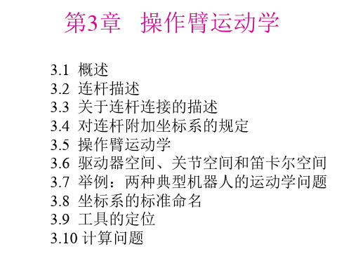
3.4 对连杆附加坐标系的规定
为了描述每个连杆与相邻连杆之间的相对位置关系,需要在每个连杆上定义一个固连 坐标系。根据固连坐标系所在连杆的编号对固连坐标系命名,因此,固连在连杆i上的 固连坐标系称为坐标系{i}。
连杆链中的中间连杆
ˆ 轴称为 Z ˆ , 坐标系{i}的 Z i 并与关节轴 i 重合,坐标系 {i}的原点位于公垂线 ai 与 ˆ沿 关节轴i的交点处。 X i ai 方向由关节 i 指向关节 i+1。
• 正运动学 • 知道操作臂的关节转角,去确定操作臂末端 执行器的位姿。
3.2 连杆描述
• 操作臂可以看成由一系列刚体通过关节连接而成的 一个运动链,我们将这些刚体称为连杆。通过关节 将两个相邻的连杆连接起来。
• 当两个刚体之间的相对运动是两个平面之间的相对滑动时,连 接相邻两个刚体的运动副称为低副。图3-1所示为六种常用的 低副关节。
例3.2 一个机器人由连杆1和连杆2两个连杆相互连接组成,如图3-3所示。关节2由连 杆1的支承“B”和连杆2的支承“A”组成,支承“A”和支承“B”的装配面为平面, 两者的装配面直接接触。求连杆偏距d2。
连杆偏距d2是关节2上的偏距,它是连杆1 和连杆 2 之间公垂线沿关节轴 2 方向的距 离。由图3-3可知, d2=2.5英寸。
当ai=0时,Xi垂直于Zi和Zi+1所在的平面。按右手定则绕Xi轴的转 角定义为αi ,由于Xi轴的方向可以有两种选择,因此αi的符号也 有两种选择。 Yi 轴由右手定则确定,从而完成了对坐标系 {i} 的 定义。图3-5所示为一般操作臂上坐标系{i-1}和{i}的位置。
中间连杆
与中间连杆i 1固接 的坐标系为 {i 1};
② ( 对首、末连杆连接的描 述 ): a) b) 1 0为原位。 d1 0为原位。
机器人学导论第五章
ω
写出例5.3中的雅克比矩阵 由例5.3的结果 式(5-55)可写出坐标系{3} 的雅克比表达式
3
l1s2 J θ l1c2 l2
0 l2
(5-66)
式(5-57)可写出坐标系{0}的雅克比表达式
3
- l1s1 l2 s12 J θ l1c1 l2c12
雅克比矩阵的定义为
建立连杆坐标系,图5-11为施加在连杆i 上的静力和静力矩(重力除外)。将这 些力相加并令其和为0,有
图5-11单连杆的静力和静力矩的平衡关系
将绕坐标系{i}原点的力矩相加,有 如果我们从施加于手部的力和力矩的描述开始,从 末端连杆到基座进行计算就可以计算出作用于每一 个连杆上的力和力矩。将以上两式重新整理,以便 从高序号连杆向低序号连杆进行迭代求解。结果如 下
例5.3 图5-8所示是具有两个转动关节的操作 臂.计算出操作臂末端的速度,将它表达成操作 臂末端的函数。给出两种形式的解答,一种是 用坐标系{3}表示,一种是用坐标系{0}表示。
图5-8两连杆操作臂
图5-9两连杆操作臂的坐标系布局
首先将坐标系固连在连杆上,计算连杆变换如 下
c1 s 1 0 T 1 0 0 s1 0 0 c1 0 0 0 1 0 0 0 1
机器人学导论
第五章 静力和速度
——新疆大学机械工程学院
第五章 速度和静力
概述 在本章中,我们将机器人操作臂的讨论扩展到静 态位置问题以外。我们研究刚体线速度和角速 度的表示方法并且运用这些概念去分析操作臂 的运动。我们将讨论作用在刚体上的力,然后 应用这些概念去研究操作臂静力学应用的问题。 关于速度和静力的研究将得出一个称为操作臂雅 克比的实矩阵。
机器人学导论第2章1
例题:坐标系F沿参考坐标系的x 轴移动9个单 位,沿z轴移动5个单位。求新的坐标系位置。 0.527 -0.574 0.628 5
0.369 0.819 0.439 3
F= -0.766 0 0.643 8
0
0
0
1
思路点拨:首先根据已知条件确定dx=9,dy=0,dz=5 之后代入公式Fnew=Trans(dx,dy,dz) ×Fold即可
理由:
1 计算方型矩阵的逆要比计算长方形矩阵的逆容 易的多
2 为使两矩阵相乘,它们的维数必须匹配。由于 要以不同顺序将许多矩阵乘在一起来得到机器人运 动方程,因此应采用方阵进行计算。
具体做法: 1 加入比例因子使之成为4 x 4矩阵,既表示姿态又 表示位置 2 只表示姿态,去掉比例因子得到3 x 3矩阵
0.707 0 0.707 5 F=
-0.707 0 -0.707 5
或 F= 0.707 0 -0.707 3 0 0 1 0 0 0 2 1
0.707 0 -0.707 3
0 1 0 2
Байду номын сангаас
0
0
0
1
除了这种解法,我们也可以利用n×o=a来求解, 大家回去不妨试试。
§2.4 齐次变换矩阵
变换矩阵应写成方型形式
P= ax i+ by j+ cz k
其中ax,by,cz是参考坐标系中表示该点的坐标。显 然,也可以用其他坐标来表示空间点的位置。
∧
∧
∧
§2.3.2 空间向量的表示
让我们再来看下面这幅图,图中的向量P该 怎样表示呢?
向量可用三个起始和终止的坐标来表示。如果 一个向量起始于A,终止于B,那么它可以表示为 PAB=(Bx-Ax)i+(By-Ay)j+(Bz-Az)k 如果一个向量的起点是原点,则上式就变成了 点的表示形式,则有: P= ax i+ by j+ cz k
机器人学导论 等效旋转矩阵
机器人学导论等效旋转矩阵机器人学导论导论机器人学是研究机器人的运动、感知、决策和控制等方面的一门交叉学科。
它涉及多个领域,如计算机科学、电子工程、力学、控制理论等。
机器人学的目标是设计和开发能够完成特定任务的智能化机器人系统。
等效旋转矩阵等效旋转矩阵是机器人运动中常用的一种表示方法。
它可以将三维空间中的旋转变换表示为一个三维矩阵,从而方便进行运动规划和控制。
1. 旋转矩阵的定义在三维空间中,一个点P(x,y,z) 绕坐标轴分别旋转角度α,β,γ 后得到新点P’(x’,y’,z’)。
则可以通过如下公式计算旋转矩阵R:其中,Rx, Ry, Rz 分别表示绕x轴、y轴、z轴旋转的矩阵,α, β, γ 分别表示绕x轴、y轴、z轴旋转的角度。
2. 等效旋转矩阵的定义在机器人运动中,通常需要将多个旋转变换组合起来来实现特定任务。
这时,可以将多个旋转变换合并为一个等效旋转变换,从而简化运动规划和控制。
等效旋转矩阵的定义如下:其中,R1, R2, …, Rn 分别表示多个旋转变换的旋转矩阵。
3. 等效旋转矩阵的计算方法计算等效旋转矩阵的方法有多种,下面介绍两种常用的方法。
(1)欧拉角法欧拉角法是一种将三个绕不同轴的旋转变换合并为一个等效旋转变换的方法。
具体步骤如下:① 将三个绕不同轴的旋转变换分别表示为三个矩阵R1, R2, R3。
② 将这三个矩阵相乘得到一个等效矩阵R = R3 × R2 × R1。
③ 将等效矩阵R分解为三个绕不同轴的旋转变换,即可得到欧拉角表示。
(2)四元数法四元数法是一种将多个旋转变换合并为一个等效旋转变换的方法。
具体步骤如下:① 将多个旋转变换分别表示为四元数q1, q2, …, q n。
② 将这些四元数相乘得到一个等效四元数q = qn × … × q2 × q1。
③ 将等效四元数q转换为等效旋转矩阵即可。
4. 总结等效旋转矩阵是机器人运动中常用的一种表示方法,它可以将多个旋转变换合并为一个等效变换,从而方便进行运动规划和控制。
机器人学导论第4章1PPT课件
即在易使工具与环境脱离接触或产生很大作用 力的方向采用柔顺控制。其方法是:假想在此方向, 末端刚度很低,对其采用力控制。
§4.2 力和力矩分析
4.2.1 力和力矩的平衡 这一节推导表示机械手静力学特性的基本方
程。我们首先考虑在开环运动链上的一个单独连 接的自由实体的图形。图4-1表示作用在连杆i上 的力和力矩。连杆i通过关节i+1与连杆i-1和连杆
第4章 力分析及柔顺控制
学习内容: 1 动力学分析 2 静力学分析 3 坐标系间力和力矩的变换 4 柔顺控制
学习重点: 1 动力学方程的简化 2 柔顺坐标系
为了使物体加速必须对其施加力,使旋转物体 产生角加速度必须对其施加力矩,所施加力、力 矩大小为:
Fma TI
为使机器人连杆加速,驱动器必须有足够大 的力、力矩驱动机器人连杆和关节,以使他们能 以期望的加速度和速度运动。为此,必须计算每 个驱动器所需的驱动力。设计者可根据这些方程 并考虑机器人外部载荷计算出驱动器可能承受的 最大载荷,并进而设计出能够提供足够力及力矩 的驱动器。
N i 1 , i N i , i 1 ( r i 1 , i r i , c i ) f i 1 , i ( r i , c i ) ( f i , i 1 ) 0i 1 , n ,(4
这里ri-1,i是从Oi-1到Oi的3×1位置矢量,而 ri,ci表示从Oi到Ci的位置矢量。力fi-1,i和力矩Ni1,i是相邻连杆i和i-1之间的耦合力和力矩。
Fmxkx
用牛顿方程:
Fma
பைடு நூலகம்
d (mx) mx dt
Fkxma Fm akx
机械手和环境之间的接触将在接触处产生相互 作用的力和力矩。每个机械手的关节运动都是由各 自的执行装置驱动的。相应的关节输入力矩,经手 臂的连杆传送到抓具,并在抓具处引起对环境的力 和力矩。
机器人学导论
机器人的动力学模型
牛顿-欧拉方程
拉格朗日方程
凯恩方法
雅可比矩阵
机器人的运动规划与控制
运动学:研究机器人末端执行器的位置和姿态信息 动力学:研究机器人末端执行器的力和力矩信息 运动规划:根据任务要求,规划机器人的运动轨迹 控制:通过控制器对机器人进行实时控制,实现运动规划
机器人的感知与感
05
知融合
01
添加章节标题
02
机器人学概述
机器人的定义与分类
机器人的定义: 机器人是一种能 够自动执行任务 的机器系统,具 有感知、决策、
执行等能力
机器人的分类: 根据应用领域、 结构形式、智能 化程度等不同, 机器人可分为多 种类型,如工业 机器人、服务机 器人、特种机器
人等
机器人学的研究领域
机器人设计:研究机器人的结构、 运动学和动力学
机器人的感知技术
添加项标题
视觉感知技术:通 过摄像头获取环境 信息,识别物体、 场景等,实现机器 人视觉导航、物体 识别等功能。
添加项标题
听觉感知技术:通 过麦克风获取声音 信息,识别语音、 音乐等,实现机器 人语音交互、音乐 识别等功能。
添加项标题
触觉感知技术:通过 触觉传感器获取接触 信息,识别物体的形 状、大小、硬度等, 实现机器人触觉导航、 物体抓取等功能。
执行器作用:根据控制信号执行相应的动作,如移动、转动等
机器人的感知系统
传感器类型:视觉、听觉、触觉等 传感器工作原理:图像处理、语音识别、触觉反馈等 传感器在机器人中的应用:导航、目标识别、物体抓取等 感知系统对机器人性能的影响:精度、稳定性、安全性等
机器人的运动学与
04
动力学
机器人的运动学方程
- 1、下载文档前请自行甄别文档内容的完整性,平台不提供额外的编辑、内容补充、找答案等附加服务。
- 2、"仅部分预览"的文档,不可在线预览部分如存在完整性等问题,可反馈申请退款(可完整预览的文档不适用该条件!)。
- 3、如文档侵犯您的权益,请联系客服反馈,我们会尽快为您处理(人工客服工作时间:9:00-18:30)。
Forward kinematics of manipulators (Chapter 3) Kinematics is the science of motion that treats motion without regard to the forces which cause it. e.g. position, velocity, acceleration and all higher order derivatives of the position variables.
Cartesian Spherical
Cylindrical
Articulated
SCARA
Topics: • Lectures: Description of position and orientation (Chapter 2) Forward kinematics of manipulators (Chapter 3) Inverse kinematics of manipulators (Chapter 4) Velocities, static forces, singularities (Chapter 5) Dynamics (Chapter 6) Trajectory generation (Chapter 7) Manipulator design and sensors (Chapter 8) Linear position control (Chapter 9) Nonlinear position control (Chapter 10) • Experiments: Programming robots and Off-line programming and simulation (Chapter 12 & 13)
accord to application fields:
Service robots Industrial robots Underwater robots Military robots
robots
Specialized robots
Agricultural robots
Robotized machine Humanoid robots Entertainment robots Aerospace robots Micro robots Medical robots
Attached to the end-effector
Attached to the base
Degree Of Freedom (DOF): In many scientific fields, the degrees of freedom of a system is the number of parameters of the system that may vary independently. (from Wikipedia) For example: • A point in the plane has two DOF for translation: its two coordinates. • A rigid body on the plane has three DOF: its two coordinates and its orientation. • A rigid body in space has six DOF: three translation and three revolution.
1.1 BACKGROUND
Yearly installations of multipurpose indusrecasts for 2001-2004
Robot prices compared with human labor costs in the 1990s
Structure of a manipulator parts: nearly rigid links connection: by joints (rotary or revolute joints, sliding or prismatic joints) joint variables: • joint angles (revolute joints) • joint offset (prismatic joints)
Summary: There is no consensus on which machines qualify as robots but there is general agreement among experts, and the public, that robots tend to do some or all of the following: accept electronic programming, process data or physical perceptions electronically, operate autonomously to some degree, move around, operate physical parts of itself or physical processes, sense and manipulate their environment, and exhibit intelligent behavior — especially behavior which mimics humans or other animals. (from Wikipedia)
The robot type of our course: industrial robots (robotic arms, manipulators)
According to designs of the first three joints:
(Manipulator structure: Positioning structure + orienting structure or wrist)
Categories of robot:
According to actuator types: •Electrical actuators •Hydraulic actuators •Pneumatic actuators •Others: piezo actuators, shape memory alloy (SMA), magnetostrictive actuators According to intelligence levels: •Normal robots: only programmable •Intelligent robots: some kind of artificial intelligence According to moveability: •Fixed robots: the base is fixed, while the joints are moveable •Mobile robots: wheel, pedrail, legged (single, double, four, six, eight)
Forward kinematics of manipulators: Given a set of joint variables, to compute the position and orientation of the tool frame relative to the base frame. in other words, to change the representation of manipulator position from a joint space description into a Cartesian space description.
教材 : • John J. Craig. Introduction to Robotics: Mechanics and Control (3rd ed). Pearson Prentice Hall. 2005. 参考资料: • [美]Saeed B.Niku著, 孙福春等译. 机器人学导论——分析、系统及应用 (第2版) (原书: Introduction to Robotics: Analysis, Systems, Applications). 电子工业出版社. 2013. • 蔡自兴, 谢斌. 机器人学(第3版). 清华大学出版社. 2015. • 谭民, 徐德等. 先进机器人控制. 高等教育出版社. 2007. • 比较知名的刊登机器人方面研究成果的期刊:《Advanced Robotics》, 《Autonomous Robots》, 《Journal of Robotic System》,《机器人》, 《自动化学报》,《机器人技术与应用》,《控制理论与应用》。 • MATLAB的Robotics工具箱(by Peter I. Corke): /Robotics_Toolbox.html 上课形式(全日制硕士-全英;在职工硕-双语): 讲授20学时、实验12学时。 考核(全日制硕士-全英;在职工硕-双语): 仿真作业,实验报告,课程论文(综述)。
Chapter 1 Introduction
What does a robot look like in your mind?
A rudiment of manipulator
Definitions of robots: Definition 1: A robot is a mechanical or virtual artificial agent, usually an electromechanical machine that is guided by a computer program or electronic circuitry. (from Wikipedia) Definition 2: An automatically controlled, reprogrammable, multipurpose manipulator, which may be either fixed in place or mobile for use in industrial automation applications. (from International Organization for Standardization (ISO) ) Definition 3: A reprogrammable, multifunctional manipulator designed to move material, parts, tools, or specialized devices through various programmed motions for the performance of a variety of tasks. (from Robot Institute of America (RIA))