AC无线管理系统平台使用说明书
rocketac说明书
rocketac说明书RocketAC产品使用说明书第一章: 产品概述1.1 前言感谢您选择RocketAC系列产品。
本说明书将详细介绍RocketAC产品的特点、功能以及使用方法。
请您在使用之前仔细阅读本说明书,并按照说明书上的指导进行操作,以充分发挥RocketAC产品的性能。
1.2 产品特点RocketAC是一款高性能的无线网络设备,采用先进的AC技术,能提供更快的传输速率和更稳定的信号覆盖。
RocketAC支持2.4GHz和5GHz频段,具有强大的信号穿透能力和广阔的无线覆盖范围。
此外,RocketAC还具有以下特点:- 高速传输: RocketAC支持最高速率达到300Mbps,在2.4GHz 频段和5GHz频段都能提供更快的传输速率,满足高网速需求。
- 强大的覆盖范围: RocketAC采用高增益天线和Beamforming技术,能提供更稳定、更开阔的无线覆盖范围,保证信号的稳定性和可靠性。
- 稳定可靠: RocketAC采用了先进的MIMO技术和多重天线传输技术,能自动选择最佳信道和避免干扰,保证信号的稳定性和可靠性。
- 简单易用: RocketAC采用智能一键连接,用户只需按下按钮即可快速建立无线网络连接,操作简单方便。
- 多种工作模式: RocketAC支持AP模式、Client模式等多种工作模式,适应不同场景和需求。
第二章: 外观设计2.1 产品外观RocketAC外观设计简约时尚,采用环保耐用的材质制造,具有良好的散热性能和耐用性。
产品外观主要由以下组件构成:- 主机: RocketAC的主机是一个紧凑的方形设计,外观上标有产品型号和品牌标志,背部有多个接口和按键。
- 天线: RocketAC配有高增益天线,天线可调节角度,提供更好的信号接收和发射效果。
2.2 接口与按键RocketAC主机背部的接口和按键包括:- 电源接口: 用于连接电源适配器。
- 以太网接口: 用于连接外部设备,如计算机或路由器。
NETGEAR 无线AC适配器(双频)操作指南说明书
Support und CommunityUnter /support finden Sie Antworten auf Ihre Fragen und die neuesten Downloads.Hilfreiche Tipps finden Sie auch in unserer NETGEAR Community unter .RechtsvorschriftenInformationen zur Einhaltung der rechtlichen Vorschriften, einschließlich der EU-Konformitätserklärung, finden Sie unter: https:///about/regulatory/.Lesen Sie das Dokument zur Einhaltung rechtlicher Vorschriften, bevor Sie das Gerät an die Stromversorgung anschließen.Gilt nur für 6-GHz-Geräte: Verwenden Sie das Gerät nur in Innenräumen. Der Betrieb von 6-GHz-Geräten auf Ölplattformen sowie in Autos, Zügen, Booten und Flugzeugen ist verboten. Davon ausgenommen ist der Betrieb dieses Geräts in großen Flugzeugen mit einer Flughöhe von über 3.000 Metern. Es ist nicht gestattet, Sender im Frequenzbereich 5,925–7,125 GHz zur Steuerung oder Kommunikation mit unbemannten Flugzeugsystemen zu verwenden.Januar 2022HINWEIS: Laden Sie die Adaptersoftware oder Standalone-Treiber von der NETGEAR Website herunter und installieren Sie sie, bevor Sie den WLAN-Adapter an Ihren Computer anschließen.NETGEAR, Inc.350 East Plumeria Drive San Jose, CA 95134, USA NETGEAR INTERNATIONAL LTD Floor 1, Building 3University Technology Centre Curraheen Road, Cork, T12EF21, Ireland© NETGEAR, Inc., NETGEAR und das NETGEARLogo sind Marken von NETGEAR, Inc. Jegliche nicht zu NETGEAR gehörende Marken werden nur zu Referenzzwecken verwendet.Über WPS eine Verbindung mit einem WLAN-Netzwerk herstellen1. Stecken Sie den Adapter in einen USB-Port an Ihrem Computer.2.3. Drücken Sie innerhalb von 2 Minuten die WPS -Taste auf Ihrem WLAN-Routeroder Gateway.Der Adapter stellt nun eine Verbindung mit einem WLAN-Netzwerk her. Dieser Vorgang kann einige Minuten dauern. Ihre Einstellungen werden in einem Netzwerk-Profil gespeichert.Mit der Adaptersoftware können Sie den Adapter mit einem WLAN-Netzwerk verbinden.1. Besuchen Sie https:///support/download/?model=&model=A6100 und laden Sie die neueste Softwaredatei herunter.2. Entpacken Sie die Dateien aus der .zip -Datei.3. Doppelklicken Sie auf die Datei, die auf .exe endet und deren Dateinamenicht Standalone enthält.4. Befolgen Sie die Anweisungen, um die Installation abzuschließen.Installieren der AdaptersoftwareVerbindung mit einem WLAN-Netzwerk herstellenSie können den WLAN-Verbindungsstatus mithilfe des Adaptersymbolsanzeigen, das in der Windows-Taskleiste angezeigt wird. Um Details zur WLAN-Verbindung anzuzeigen, öffnen Sie die Adaptersoftware.Die Farbe des Symbols zeigt die Signalstärke Ihrer WLAN-Verbindung an: • Weiß: Gute Verbindung • Gelb : Schwache Verbindung •Rot : Keine VerbindungWenn Sie den Adapter entfernen, ist die Adaptersoftware nicht mehr verfügbar und das Symbol wird nicht angezeigt. Wenn Sie den Adapter wieder anschließen, wird das Symbol wieder angezeigt.Anzeigen des VerbindungsstatusMit dem Standalone-Treiber können Sie die integrierten Windows WLAN-Netzwerkeinstellungen Ihres Computers verwenden, um den Adapter an ein WLAN-Netzwerk anzuschließen, anstatt die Adaptersoftware zu verwenden.1. Besuchen Sie https:///support/download/?model=&model=A6100 und laden Sie die neueste Softwaredatei herunter.2. Entpacken Sie die Dateien aus der .zip -Datei.3. Doppelklicken Sie auf die Datei, die auf .exe endet und deren DateinameStandalone enthält.4. Befolgen Sie die Anweisungen, um die Installation abzuschließen.Installieren des Standalone-TreibersSie können die Verbindung mit einem WLAN-Netzwerk über dieAdaptersoftware, die in Ihrem Computer integrierten Windows WLAN-Netzwerkeinstellungen oder über WiFi Protected Setup (WPS) herstellen, sofern Ihr WLAN-Router dies unterstützt.Über die Adaptersoftware eine Verbindung mit einem WLAN-Netzwerk herstellen1. Vergewissern Sie sich, dass die Adaptersoftware installiert ist.Weitere Informationen finden Sie unter Installieren der Adaptersoftware .2. 3. Adaptersoftware zu starten.4. Klicken Sie auf die Schaltfläche Join a Network (Netzwerkverbindungherstellen).5. Wählen Sie ein WLAN-Netzwerk.6. Klicken Sie auf die Schaltfläche Connect (Verbinden).7. Wenn das WLAN-Netzwerk gesichert ist, geben Sie das Passwort oder denNetzwerkschlüssel ein.Der Adapter stellt nun eine Verbindung mit einem WLAN-Netzwerk her. Dieser Vorgang kann einige Minuten dauern.Über die integrierten Windows-Netzwerkeinstellungen eine Verbindung mit einem WLAN-Netzwerk herstellen1. Vergewissern Sie sich, dass der Standalone-Treiber installiert ist.Weitere Informationen finden Sie unter Installieren des Standalone-Treibers .2. Stecken Sie den Adapter in einen USB-Port an Ihrem Computer.3. Öffnen Sie die WLAN-Netzwerkeinstellungen auf Ihrem Computer undwählen Sie ein WLAN-Netzwerk aus, um eine Verbindung herzustellen.Weitere Informationen zum Herstellen einer Verbindung mit einem WLAN-Netzwerk über Ihren Computer finden Sie auf der Windows-Supportseite von Microsoft.。
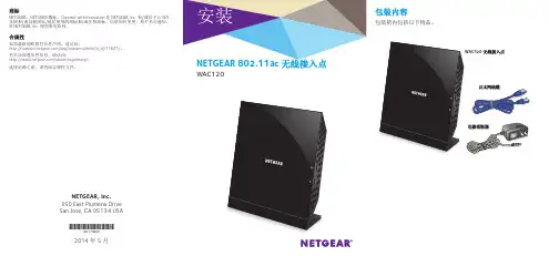
NETGEAR WAC120 802.11ac 无线接入点说明书
NETGEAR, Inc.350 East Plumeria Drive San Jose, CA 95134 USA2014 年 5 月商标NETGEAR 、NETGEAR 徽标、Connect with Innovation 是 NETGEAR, Inc. 和/或其子公司在美国和/或其他国家/地区使用的商标和/或注册商标。
信息如有变更,恕不另行通知。
© NETGEAR, Inc. 保留所有权利。
合规性如需最新的欧盟符合性声明,请访问:/app/answers/detail/a_id/11621/。
有关法规遵从性信息,请访问:/about/regulatory/。
连接电源之前,请查阅合规性文件。
技术支持感谢您选择 NETGEAR 产品。
安装设备后,请找到产品标签上的序列号并使用它在 https:// 上注册产品。
只有在注册产品后,才能使用 NETGEAR 电话支持。
NETGEAR 建议通过 NETGEAR 网站注册产品。
如需联系 NETGEAR 支持部门,请访问:/general/contact 或致电(仅限美国) 1-888-NETGEAR 。
在其他国家/地区,请访问:/general/contact/default.aspx 查看电话 号码。
如需产品更新和网络支持,请访问 。
NETGEAR 建议您只使用 NETGEAR 官方支持资源。
可通过产品的用户界面中的链接或 在线获取用户手册。
客服热线:400-830-3815电子邮件支持:**********************中文技术支持站点:/ 网件社区:您可以使用这些图解来连接您的无线接入点,或遵循本手册中的详细说明。
选项 11. 为您的网络配置接入点。
如需了解更多信息,请参阅第 2 页上的设置接入点。
2. 将您的调制解调器连接到 Internet 。
3. 将调制解调器连接至接入点背后的 LAN 端口。
选项 21. 为您的网络配置接入点。
ac900双频无线扩展器说明书

ac900双频无线扩展器说明书
1、电脑连接扩展器默认信号:将扩展器插在充电器的USB接口(或移动电源、电脑等设备的USB接口)。
扩展器会发射无线信号。
这个信号是临时用来设置扩展器的,设置完成后该信号就消失了。
2、进入扩展器管理界面:打开电脑上的浏览器,清空地址栏并手动输入登录地址,出现登录页面后,设置一个6位及以上的管理扩展器的密码,设置完成后点击开始设置扩展器。
3、扫描信号:进入扩展器设置界面,扩展器会自动扫描周边信号,等待一会。
在扫描到的信号列表中找到您要扩展的信号,选择信号(如果搜索不到,信号可能太弱或者为中文信号,请修改待扩展信号的名称)。
4、在扫描到的信号列表中找到您要扩展的信号,选择信号(如果搜索不到,信号可能太弱或者为中文信号,请修改待扩展信号的名称)。
其实所有的扩展器设置都差不多,都可以简单总结为四个过程:放置并供电(给扩展器);搜索信号(用手机或者电脑);选择相应的登录界面;选择信号,设置密码。
最后就设置成功了!。
tpac2000无线ap说明书
tpac2000无线ap说明书tpac2000无线AP是一款高性能、稳定可靠的无线接入点,适用于家庭、企业、学校等场景。
本说明书将为您介绍产品的功能、安装方法、使用技巧以及安全维护等方面的内容。
一、产品简介tpac2000无线AP采用先进的无线技术,提供稳定的Wi-Fi连接。
它支持多种无线标准,如802.11ac、802.11n等,可实现高速数据传输。
此外,tpac2000还具备良好的穿墙性能,确保信号覆盖范围广泛。
二、主要功能1.高速无线网络:支持802.11ac/n/g/b等多种无线标准,提供高达300Mbps的传输速率。
2.穿墙性能:优化信号传输,增强穿墙能力,扩大覆盖范围。
3.支持多种接入方式:支持以太网线、Wi-Fi等方式接入网络。
4.安全防护:具备WPA/WPA2加密技术,保障网络安全。
5.无线中继:支持无线信号中继,扩大信号覆盖范围。
三、安装与配置1.准备工作:确保电源插座附近有可用的网络接口。
2.接通电源:将无线AP插入电源插座,启动设备。
3.连接网络:用网线将无线AP与路由器或交换机相连。
4.配置网络:通过Web管理界面或手机APP进行网络配置。
四、使用方法1.连接无线网络:手机、电脑等设备搜索并连接无线网络。
2.配置设备:进入设备管理界面,根据需求调整无线网络参数。
3.管理设备:通过Web管理界面或手机APP实时监控设备状态,进行故障排查。
五、安全与维护1.安全设置:启用WPA/WPA2加密,确保网络安全。
2.定期更新:关注厂家更新,及时更新固件,提升设备性能。
3.故障排查:遇到问题及时联系技术支持,或参考说明书进行排查。
六、技术支持如需进一步了解产品详情或遇到使用问题,请随时联系售后技术支持。
我们将竭诚为您服务,解决您的疑虑。
请注意,本说明书的操作步骤仅供参考,实际操作可能因设备型号、软件版本等因素有所不同。
如有疑问,请参阅产品说明书或联系技术支持。
Ubiquiti UAP-AC-LITE 无线接入点用户手册说明书

WA-2200 802.11ac 2x2 Wave 2 无线接入点用户指南说明书
WA-2200Wireless Access Point User GuideContentsIntroduction3 System requirements3 Hardware installation3 Default settings and credentials3 First-time login3 Configure4 Overview6 Connections78 Backup/Restore9 Logs10 Advanced11 Device Settings11 LAN Settings11 Wireless Settings11 Access Control14 Firmware14 BakPak Lite16 BakPak Lite16 Reset to factory default settings18 Reset using the interface18 Reset using the physical RESET button18IntroductionAs the central component of your wireless network,the WA-2200802.11ac2x2Wave2 Access Point provides you with high-speed,high-range wireless8012.11ac networking.The AP broadcasts on both the5GHz and2.4GHz bands so that select devices can choose their preferred source of wireless connectivity,improving the overall stability,reliability,and performance of the wireless network.l For product regulatory information,see ctrl4.co/reg.l For product patent information,see ctrl4.co/patents.System requirementsMinimum system requirements:l PoE switch or injector,or an AC power adapter(not included).l A computer with an Ethernet port(for first AP setup).Hardware installationFor hardware installation and first-time startup instructions,see the Quick Start Guide found in the box.Default settings and credentialsl IP address:IP will be automatically assigned by router if a DHCP server is detected or,if no DHCP server is detected,the default IP address will be automatically set to192.168.1.21.l Username/Password(default):admin/passwordl SSIDs(default):Pakedge_Main(5GHz)and Pakedge_Alt(2.4GHz) Security/password:WPA2-PSK/pakedgewirelessl Guest SSIDs(default):PakedgeGuest2.4and PakedgeGuest5,security/password: WPA2/pakedgeguestl Transmit power for US and International models(WA-2200and WA-2200-C,WA-2200-1and WA-2200-C-1)18dBm for5GHz and13dBm for2.4GHzFirst-time loginThe first time you log in,you are brought to the Configure tab.Here you can change your username and password(strongly recommended),specify the device’s network name and physical location,set the Country Code,and create or hide wireless networks.For BakPak Lite setup instructions,see the WA-2200Quick Start Guide.ConfigureThe Configure tab allows you to change the most common AP settings in one screen.This is the default tab that displays after login.l Username and Password:The first time you log in,you should change these from the defaults(“admin”and“password”)to new credentials.l Friendly Device Name:Give the AP a descriptive name to identify it on its web interface screen and in BakPak.l Device Location:Describe the physical location of the AP here.l Device Note:Add any other notes here,such as date of installation and the technician name.l Time Zone:Select the time zone used for the AP’s event logs.l Country Code:Select the country where the AP is installed.l LAN Settings:l IP Network Settings:Select the method used for assigning IP addresses(DHCP or Static).l IP Address:For a static IP network,enter the AP’s IP address here.For a DHCP network,this field is read-only.l Subnet Mask:For a static IP network,enter the AP’s subnet mask here.For a DHCP network,this field is read-only.l Gateway:For a static IP network,enter the AP’s Gateway address here.For a DHCP network,this field is read-only.l DNS Settings:l DNS Server n(server’s IP address):For a static IP network,enter up to two DNS server IP addresses here.For a DHCP network,these fields are read-only.l5GHz Networks and2.4GHz Networks,and guest networks:Enter an SSID(wireless network name),the authentication type to use,the WiFi password,and the VLAN this wireless network is associated with.To view the password that’s entered,click the eye icon.Select Hide to not broadcast the wireless network’s SSID.l5GHz Guest Network and2.4GHz Guest Network:Enter an SSID(wireless network name),the authentication type to use,and the WiFi password.To view the password that’s entered,click the eye icon.Select Hide to not broadcast the wireless network’s SSID.OverviewThe Overview tab gives you a quick view of the AP’s status and critical settings.l Notifications:System notifications display at the very top of the tab.This example showsa firmware update is available.l Name:The device name(assigned in the Configure tab)appears here.l IP address and MAC address:The device’s assigned IP address and unique MAC address is shown here.l Update Firmware:Click to open the Update Firmware screen(also accessible under the Advanced tab).The screen also displays the firmware’s release notes.l Restart device:Click to restart(power cycle)the AP.It happens immediately,with no confirmation dialog.l Network information:Displays the number of wireless network SSIDs and the number of channels used by each.l Services:Displays the status of current services and settings and indicates with an icon whether the service or setting is optimally configured.ConnectionsThe Connections tab displays a list of connected wireless devices.Click any column head to sort the list by that field.Available fields are: l Hostnamel IP Addressl MAC Addressl Device OSl Connected Tol Strengthl Bandl Durationl TX/RXBackup/RestoreThe Backup/Restore tab allows you to save a configuration(backup)and restore the configuration file.l Save Configuration:Click to save a file that contains all of this AP’s settings.l Choose File:Click to select a saved configuration backup file to use for restoring settings.l Restore:Click to restore AP settings using the selected configuration backup file.LogsThe Logs tab displays a record of system events effected by the AP.The events are categorized and sortable by severity,timestamp,and details.l Enable Remote Syslog to save the logs on another network.You’ll also need to specify the remote Syslog server IP address and port.l Download Detailed Logs:Click to download more verbose descriptions of the logged events.AdvancedDevice SettingsClick this tile to configure LED settings,change the hostname or factory defaults,or to access diagnostic tools.l LEDs:Select to enable(or deselect to disable)the AP’s LEDs.l Hostname:Enter the hostname here.l Factory Default:Click to restore factory default settings.l Diagnostic Toolsl Ping:Select to ping a device at the indicated address.l Traceroute:Select to run a traceroute to the indicated address.LAN SettingsClick this tile to configure the advanced LAN port settings,such as management VLAN and STP.l Management VLAN:Click this toggle to enable the management VLAN.l VLAN ID:Enter the VLAN ID the AP is associated with.l Spanning Tree Protocol:Click this toggle to enable spanning tree protocol,then select Priority to change the priority from its default(32768).The lower the priority,the more likely the switch is to become the root bridge.(STP is changed in increments of4,096.) Wireless SettingsClick this tile to configure advanced WiFi radio settings such as channel,power,RF scan,and roaming features.l Wireless Settingsl Band Steering:Band steering steers5GHz-capable clients to that frequency.By enabling this function,the2.4GHz SSID and settings will be copied to the5GHzband.l RF Scan:Click to perform an automatic site survey of RF signals.The AP will scan the channels for connected devices and will then display them in a table.l5GHz and2.4GHz Radio Settingsl Enable:Click this toggle to enable this WiFi radio band.l Operation Mode:Both the5and the2.4GHz bands have the following operating modes:l Access Point:Standard mode of operation.Allows a wireless connection to the LAN.l WDS Root:The AP with this mode set will be the“root”device that APs configured with WDS Repeater and WDS Bridge will connect to.l WDS Bridge:This mode allows the AP to connect to a WDS Root Access Point.This mode takes in the SSID broadcasted by the WDS Root Access Point andturns it into Ethernet connectivity for client devices.l WDS Repeater:This mode allows the AP to connect to a WDS Root Access Point.This setting will take the SSID broadcasted by the WDS Root Access Pointand rebroadcast it to end-user devices.l Additional WDS Bridge and WDS Repeater settings:l WDS Root Access Point BSSIDl WDS Root Access Point SSIDl Wireless Mode:Choose the setting that corresponds to the type of wireless clients connected to your network.If you aren’t sure which type of clients will access thewireless networks,we recommend you keep the default settings.l Channel Width:Select the channel width for the selected channel to use.By default, it’s set to HT80MHz(when using5GHz)and HT20MHz(when using2.4GHz).Selecting40 MHz on the2.4 GHz band is possible,but not recommended,because itwill also increase the risk of impacting wireless performance.We recommend keepingthe2.4 GHz radio set to20 MHz and using only channel1,6,or11,because they are the only three non-overlapping channels.l Channel:Using the default setting(Auto),the AP automatically selects the channel with best performance for the wireless network.To select a channel manually,clickthe drop-down list and select a channel.The channel options available depend on the Country Code selected.l Transmit Power Level:The power depends on the distance of the devices in your wireless network.You can use this feature to increase or decrease the coverage area;however,we do not recommend changing this setting unless a professional sitesurvey is conducted.Contact your network administrator for help.l Auto:This setting adjusts the power of the AP based on the distance to the furthest client device.l For US model s(WA-2200and WA-2200-C):11dBm(13mW)–25dBm(316mW):These are static power settings.The AP willbroadcast at the selected power level.l For international model s(WA-2200-1and WA-2200-C-1):Transmit Power Level for International version depends on the Country Code selected(see page3).l Multicast Handling:Enable the Convert to Multicast toggle to enhance the video/audio quality when streaming multicast content to multiple devices over WiFi.When enabled,all the multicast traffic is converted to unicast,which increases thedelivery speed to individual devices.This feature is not recommended if the multicast group exceeds10devices.l Roamingl Fast BSS transition(802.11r):IEEE802.11r standard for fast roaming reduces the authentication time when clients roam from one AP to the other.This featureis beneficial for video streaming and voice application.l Client Reject RSSI:Helps with“sticky”clients that don’t reliably roam to the closest AP.By enabling this feature,the AP continuously monitors the station’sreceived signal and will de-authenticate the client when the RSSI falls below theuser-defined Client Reject RSSI Value threshold.This setting can be configuredindependently on5GHz and2.4GHz radios.l Guest Network Client IP Assignmentl DHCP:Select Internal or External.l Starting IP Address:This is the beginning of the DHCP range used on the guest network.If you have multiple APs,you can give them the same DHCP range because the guest network of each AP will be independent of each other.l Ending IP Address:This is the last IP address available on the DHCP range.l Subnet Mask:Select the class of the guest network.255.255.255.0is the standard setting and is selected by default.l GW IP Address:Enter the Gateway IP addressl DNS server IP address:The DNS Server IP can be set to an external DNS or to the router’s IP address if the router provides a DNS server.Access ControlClick this tile to set up access control for connected clients.To add a client for access control,click Add,then select the client and click Apply.The client and its identifying information are added to the Access Control list.Click any column head to sort the list by that field.Available fields are:l Hostnamel IP Addressl MAC Addressl RemoveFirmwareClick this tile to access cloud and local firmware upgrades.If your firmware is up to date,this screen shows your current firmware version and provides a link for that firmware’s release notes.If a firmware update is available,this screen also shows the update version and the update’s release notes.Click Upgrade to update the firmware from the cloud.BakPak LiteBakPak Lite is designed to provide remote cloud monitoring and configuration to the ing BakPak,you can remotely monitor and configure your customer’s AP without requiring a truck roll or a VPN session to the customer’s network.In just a few clicks,register your AP with your new or existing BakPak account.Registration is a two-step process where you register the Management Agent in BakPak,and then you link the management agent to an existing site or create a new site.BakPak LiteThe AP has BakPak Lite built in,which means it can remotely monitor other WE Series APs via BakPak.After the AP has been enrolled in BakPak,you can access it from anywhere in the world by using the BakPak app or the web interface at .If you see this message bar at the top of your access point’s web interface,the AP is not yet enrolled in BakPak.To enroll the AP in BakPak:1.On the message bar,click Click here to enroll.You are automatically redirected to.2.Log in with your BakPak credentials or create a new admin account.When you arelogged in,the serial number and MAC address will be automatically populated on yourBakPak account.To log in and view a site using the web interface:1.In a web browser,log in to .2.Under Sites,click Manage.A list of BakPak and BakPak Lite sites opens.3.Click the site you want to access,then click the BakPak Lite device that you want tomanage.The site’s management window expands,providing the following information:l Device information:Identifies all information about the device,including the serial number and firmware version,and has ability to reboot the wireless router remotely.l SSID configuration:Configure/edit wireless information for the primary SSID and guest networks.l Network Settings:Allows control of network settings such as DHCP,Spanning Tree Protocol,and Management VLAN.l Advanced Settings:Remotely configure the AP’s advanced settings(set the Country Code and Time Zone and enable bandsteering)and control5GHz and2.4GHz radio settings(Channel,Channel Width,Wireless Mode,Operation Mode,Transmit Power Level,Fast BSS Transition,and Client Reject RSSI).l Connected Clients:View information on connected clients,such as the SSID, Device OS,Hostname,Signal Strength,MAC Address,and IP Address.l Events:Displays network analytics,including a log of user events,for network troubleshooting.l Firmware:Applies firmware updates to the device.l Configuration:View the configuration files available on the ing the buttons, Apply a configuration file to the AP or delete the configuration files you are no longer using.Reset to factory default settingsWhile setting up or troubleshooting,you may need to reboot the AP or restore it to its factory default settings.Reset using the interfaceTo only restart the AP,maintaining all settings:1.In the Overview or Connections tab,click Restart Device.The AP restarts.To reset to factory default settings,deleting all user settings:1.Go to the Advanced tab and click Device Settings.2.Click Factory Default,then click Yes.Reset using the physical RESET buttonYour AP has a recessed RESET button accessible through a pinhole next to the Ethernet port underneath the AP.To only reboot the AP,maintaining all settings:1.While power is connected,insert a narrow,pointed object(such as a straightened paperclip)into the hole.2.Press and release the button.To reset to factory default settings,deleting all user settings:1.While power is connected,insert a narrow,pointed object(such as a straightened paperclip)into the hole.2.Press and hold the button for at least ten seconds,then release it.Copyright ©2020,Wirepath Home Systems,LLC.All rights reserved.Control4and Snap AV and theirrespective logos are registered trademarks or trademarks of Wirepath Home Systems,LLC,dba “Control4”and/or dba “SnapAV”in the United States and/or other countries.4Store,4Sight,Control4My Home,Snap AV,Araknis,Autonomic,BakPak,Binary,Dragonfly,Episode,Luma,Mockupancy,Nearus,NEEO,OvrC,Pakedge,Sense,Strong,SunbriteTV,Triad,Visualant,WattBox,and Wirepath are also registeredtrademarks or trademarks of Wirepath Home Systems,LLC.Other names and brands may be claimed as the property of their respective owners.All specifications subject to change without notice.200-00576-E MS2020-09-2211734S Election RoadDraper,UT 84020。
TP-Link Archer C20 AC750 无线双频路由器 安装指南说明书
Archer C20AC750 Wireless Dual Band RouterREV1.0.0COPYRIGHT & TRADEMARKSSpecifications are subject to change without notice. is a registered trademark of TP-LINK TECHNOLOGIES CO., LTD. Other brands and product names are trademarks or registered trademarks of their respective holders.No part of the specifications may be reproduced in any form or by any means or used to make any derivative such as translation, transformation, or adaptation without permission from TP-LINK TECHNOLOGIES CO., LTD. Copyright © 2016 TP-LINK TECHNOLOGIES CO., LTD. All rights reserved.FCC STATEMENTThis equipment has been tested and found to comply with the limits for a Class B digital device, pursuant to part 15 of the FCC Rules. These limits are designed to provide reasonable protection against harmful interference in a residential installation. This equipment generates, uses and can radiate radio frequency energy and, if not installed and used in accordance with the instructions, may cause harmful interference to radio communications. However, there is no guarantee that interference will not occur in a particular installation. If this equipment does cause harmful interference to radio or television reception, which can be determined by turning the equipment off and on, the user is encouraged to try to correct the interference by one or more of the following measures:∙Reorient or relocate the receiving antenna.∙Increase the separation between the equipment and receiver.∙Connect the equipment into an outlet on a circuit different from that to which the receiver is connected.∙Consult the dealer or an experienced radio/ TV technician for help.This device complies with part 15 of the FCC Rules. Operation is subject to the following two conditions:1)This device may not cause harmful interference.2)This device must accept any interference received, including interference that may cause undesired operation.Any changes or modifications not expressly approved by the party responsible for compliance could void the user’s authority to operate the equipment.Note: The manufacturer is not responsible for any radio or TV interference caused by unauthorized modifications to this equipment. S uch modifications could void the user’s authority to operate the equipment.FCC RF Radiation Exposure Statement:This equipment complies with FCC RF radiation exposure limits set forth for an uncontrolled environment. This device and its antenna must not be co-located or operating in conjunction with any other antenna or transmitter.“To comply with FCC RF exposure compliance requirements, this grant is applicable to only Mobile Configurations. The antennas used for this transmitter must be installed to provide a separation distance of at least 20 cm from all persons and must not be co-located or operating in conjunction with any other antenna or transmitter.”This device is restricted in indoor environment only.CE Mark WarningThis is a class B product. In a domestic environment, this product may cause radio interference, in which case the user may be required to take adequate measures.RF Exposure InformationThis device meets the EU requirements (1999/5/EC Article 3.1a) on the limitation of exposure of the general public to electromagnetic fields by way of health protection.T he device complies with RF specifications when the device used at 20 cm from your body. Restricted to indoor use.Canadian Compliance StatementThis device complies with Industry Canada license-exempt RSS standard(s). Operation is subject to the following two conditions:(1)This device may not cause interference, and(2)This device must accept any interference, including interference that may cause undesired operation of the device.Cet appareil est conforme aux norms CNR exemptes de licence d’Industrie Canada. Le fonctionnement est soumis aux deux conditions suivantes:(1)cet appareil ne doit pas p rovoquer d’interférences et(2)cet appareil doit accepter toute interférence, y compris celles susceptibles de provoquer un fonctionnement non souhaité de l’appareil.Industry Canada StatementCAN ICES-3 (B)/NMB-3(B)Korea Warning Statements당해무선설비는운용중전파혼신가능성이있음.NCC Notice & BSMI Notice注意!依據低功率電波輻射性電機管理辦法第十二條經型式認證合格之低功率射頻電機,非經許可,公司、商號或使用者均不得擅自變更頻率、加大功率或變更原設計之特性或功能。
AC800MN-2W 扩频无线 MESH 组网模块使用手册说明书
AC800MN-2W扩频无线MESH 组网模块AC800MN-2W——分布式MESH 组网——使用手册版本号:V3.7深圳市安传物联科技有限公司邮箱:****************网站:地址:深圳市宝安区福永天瑞伟丰互联网+创业园A5栋613安传物联联安传物联联安传物联安传物联安传物联安传物AC800MN-2W目录一、产品概述...................................................................3二、产品特点...................................................................3三、应用领域...................................................................3四、尺寸结构..................................................................4五、引脚定义...................................................................4六、技术参数...................................................................5七、组网介绍和应用 (5)7.1组网跳级介绍............................................................57.2组网应用介绍............................................................5八、MESH 分布式路由协议简介.....................................................7九、参数配置 (9)9.1硬件连接................................................................99.2参数配置................................................................99.3MESH 组网配置工具软件主界面............................................109.4软件功能说明.. (10)9.4.1查看路由功能.....................................................129.4.2查看完整路径功能. (13)十、指令解析 (13)(一)帧格式 (13)1.1通用帧格式.........................................................131.2帧头说明...........................................................131.3帧负荷.............................................................141.4帧尾...............................................................15(二)配置操作命令帧格式.. (15)1.1读、写配置信息请求................................................151.2读路由信息请求....................................................171.3读版本信息请求....................................................181.4复位请求..........................................................18(三)应用数据帧格式 (19)1.1禁止路由、自动路由与强制路由数据帧格式.............................191.2源路由数据帧格式 (20)十一、无线升级................................................................22十二、天线选择................................................................23十三、使用须知. (24)1)数据延迟...............................................................242)流量控制...............................................................243)差错控制...............................................................24十四、注意事项................................................................24十五、故障排除. (24)安传物联联安传物联联安传物联安传物联安传物联安传物AC800MN-2W 是一款高性能、低功耗、远距离的微功率无线MESH 组网模块,内嵌无线MESH自组网协议,MESH 是分布式的对等网状网络,能够充分利用网络中的路由冗余,具有优异的网络自愈性、稳定性和极佳的数据吞吐量,其组网耗时很短,所有的设备上电即工作,支持7级路由,网络覆盖范围达到21公里以上。
AC2000操作使用说明书
额外系统,菜单7…………………………………………………………………………………… 49 静压,菜单8………………………………………………………………………………………… 49 设置,菜单91…………………………………………………………………………………………50 通风及风帘级别,菜单92,菜单95…………………………………………………………………51 继电器布局,菜单93…………………………………………………………………………………52 传感器布局,菜单94…………………………………………………………………………………53
温度表,菜单1……………………………………………………………………………………22 最高、最低通风级别,菜单2……………………………………………………………………24 湿度表,菜单3……………………………………………………………………………………24 制冷表,菜单4……………………………………………………………………………… 24
喂料周期,菜单7………………………………………………………………………………64 鸡舍管理………………………………………………………………………………………………64 死亡率,菜单11………………………………………………………………………………………64 产蛋量,菜单14………………………………………………………………………………………64 公鸡/母鸡曲线,菜单96………………………………………………………………………………65 主要部件及参数 LCD,键盘 背光液晶显示器,2行20个字符实现用户界面。键盘可用来输入数据及设置来实现控制。 继电器,扩展继电器 20个自带继电器,在更大的系统中可选用扩展继电器。 鸡称扩展 可连接2台精确的鸡称RBS-1,能得到精确的测量值 加热区,传感器 可设置3个加热区的精确控制。可以选择集成的湿度及压力传感器。
- 1、下载文档前请自行甄别文档内容的完整性,平台不提供额外的编辑、内容补充、找答案等附加服务。
- 2、"仅部分预览"的文档,不可在线预览部分如存在完整性等问题,可反馈申请退款(可完整预览的文档不适用该条件!)。
- 3、如文档侵犯您的权益,请联系客服反馈,我们会尽快为您处理(人工客服工作时间:9:00-18:30)。
AC无线管理系统g平台--------使用手册2014年1月无线管理平台简介欢迎使用YC2000无线管理系统平台,用于吸顶AP集中布网和集中维护,简化吸顶AP集中使用时的各项操作和减少布网及维护成本。
YC2000无线管理系统平台以简洁、易操作的用户界面,成功的实现了网络管理员对网络各个吸顶AP的轻松控制和维护,大大的节省了布网和管理、维护网络的成本!下面我们将对于YC2000无线管理系统平台的使用环境、安装、操作进行详细的说明。
1.1操作系统●WINDOWS7●WINDOWS8●WINDOWS2000/XP1.2软件加密●USB加密KEY1.3软件存贮●安装CD●合法COPY的安装文件注意软件安装安装YC2000无线管理系统平台,请关闭杀毒软件或者将YC2000无线管理系统平台添加到杀毒软件信任列表,否则有可能不能成功安装本管理软件。
2.1第一步启动安装如下图示,首先进入软件所在的目录,找到安装文件图1第一步找到安装软件2.2第二步双击无线管理系统平台安装文件,进入安装向导,点击下一步图2第二步运行安装软件选择软件安装目录,一般默认目录安装就可以了,点击下一步图3第三步创建程序的安装目录2.4第四步创建程序文件夹,直接点击下一步图4第四步创建文件夹创建程序桌面图标和快速启动图标,为了方便使用,选择创建,点击下一步图5第五步创建快捷方式2.6第六步准备安装,确认需要安装的信息无误后,点击安装。
图6第六步安装完成安装,确认USB加密KEY已插入本机,点击完成就可以正常使用本软件了图7第七步插入KEY并完成软件登录及图标3.1用户登录如下图示,本软件默认用户名:admin密码:admin正确输入后,点击确定按钮图8登录界面注意:要先插入加密key后,才可以登录无线管理平台,否则会提示错误3.2主程序界面如下图示,进入主程序后,系统提示输入AP管理服务器地址,本地址的设定,用于AP上报信息的目标地址,如果我们设定不正确,将收集不到网内分布AP的各项信息,所以我们要确认PC端连接网内AP的网卡地址,并同时和各个受管的AP的访问地址在同一网段并正确,这里我们例举192.168.0.X 网段,PC使用网卡的IP地址配置成192.168.0.254,管理服务器的IP地址也设置成立192.168.0.254,这样我们就可以收集192.168.0.X的吸顶AP上报的各项信息了图9主程序界面3.3图标说明图10功能图标WLAN分组管理图标,主要功能实现无线吸顶AP分组配置和管理连接设备图标,可通过IP地址和MAC地址手动连接指定的无线吸顶AP删除设备图标,在设备列表里对选定的无线吸顶AP进行删除操作配置设备位置图标,对列表里的AP进行布网位标示(简单的描述吸顶AP所在位置)导出EXCEL图标,可以将受管理的无线吸顶AP列表导出到EXCEL文件,方便统计工作用户图标,是配置管理软件的登录口令及密码全网探测无线设备图标,用于下发管理服务器地址和搜索网内无线吸顶AP配置设备图标,用于对选中设备进行参数配置(包括设备的IP地址、SSID、信道等)保存日志图标,用于保存各个无线AP动作状态生成的日志清除日志图标,用于清除日志列表关于图标,显示软件版本相关信息退出系统图标。
详细操作说明4.1下发服务器地址和搜索网内无线吸顶AP点击全网探测无线设备图标,出现如下对话框,输入正确服务器地址,点击全网探测无线设备按钮图11探测无线设备执行服器地址下发和搜索后,如下图示,我们找到IP地址分别为192.168.0.1和192.168.0.98这两个无线吸顶AP,在日志列表分别提示了信息,在实际应用中,第一次布网设备时,由于无线吸顶AP 的IP地址都是统一默认为一样的,所以布网时,每加入一个无线吸顶AP都要及时的搜索到此AP,并修改此AP的IP地址,比如从192.168.0.200开始,顺序增加成192.168.0.201192.168.0.202。
以此类推,完成所有网内无线吸顶AP的服务器地址下发和配置各不相关的IP地址,核对AP列表与实际接入网内的无线吸顶AP个数,完成布网工作。
图12探测到的列表4.2无线吸顶AP的位置和名称配置该功能主要是标记无线吸顶AP在网内的物理位置信息。
接下来我们选择Ip地址为192.168.0.1的无线吸顶AP,点击图标进行配置,如下图示图13配置无线AP的物理位置输入该AP需要登记的位置信息,点击确认,此时服务器开始下发配置信息到对应的AP端,完成后如下图示,这样我们就给此AP登记了相应的物理位置信息,便于后续维护,其他AP也照此例配置就可以了图14配置完AP的位置4.3配置选定设备参数我们在设备布网成功后,需要对各个吸顶AP进行相应的参数配置,比如IP地址、无线SSID、无线信道、无线密码等相关参数进行配置。
首先我们选定设备,这里我们选中AP001,点击,如下图示。
首先对话框显示的是对应AP的状态信息图15配置AP的基本参数下面,我们进行局域网配置,也就是更改AP的IP地址和默认的子网掩码,如下图示,选择局域网配置,这里我面将AP001的IP地址修改成192.168.0.200(用户可根据实际情况修改),子网掩码为255.255.255.0,如下图所示图16配置AP的局域网IP地址下面,我们进行无线基本配置,如下图示,选择无线基本配置,如下图示,我们先配置无线SSID图17配置AP的无线配置然后,再配置无线安全,如下图示,我们选择好安全模式,再输入自己喜欢的密码,点击确定按钮后,就完成了无线全安全配置。
图18配置AP的无线安全无线高级配置,如下图示,我们点击无线高级配置,这里我们主要配置无线信道,我们将AP001,配置成6信道,AP002配置成11信道。
因为无线信道存在同信道干扰和邻信道干扰,我们在配置同一区域的无线AP信道时,一般按1、6、11分开错位配置,以尽量减少AP间的干扰。
完成配置后,点击下方应用按钮,服务器开始下发配置参数,在日志列表将会有各AP的提示信息。
完成配置下发后,弹出系统执行成功对话框,点确定,完成并退出配置参数界面。
图19配置AP的高级无线设置图20应用配置4.4划分WLAN分组如果对某些用户重新进行网段分配,需要网络管理员对网络系统的物理结构重新进行调整,甚至需要追加网络设备,增大网络管理的工作量。
而对于采用WLAN技术的网络来说,一个WLAN可以根据部门职能、对象组或者应用将不同地理位置的网络用户划分为一个逻辑网段。
在不改动网络物理连接的情况下可以任意地将工作站在工作组或子网之间移动。
利用虚拟网络技术,大大减轻了网络管理和维护工作的负担,降低了网络维护费用。
在一个交换网络中,WLAN提供了网段和机构的弹性组合机制。
点击图标会弹出下图所示界面,在这您可以添加WLAN分组、修改WLAN分组、删除WLAN分组、将AP添加至WLAN分组和删除。
其中修改和删除操作时需要先选中一个WLAN分组,才可以进行后续的操作。
图22划分WLAN再点击添加配置分组,弹出下图所示界面,在这里我们可以配置WLAN的SSID、信道等参数。
图23WLAN分组设置在上述操作完成后,点击应用,再回到WLAN配置分组界面,选中刚刚添加的WLAN分组,再点击选择AP加入WLAN分组。
图24添加WLAN成员点击选择AP加入WLAN分组,会弹出下图所示界面,再选中您想添加的AP,点击添加并应用WLAN 分组配置,如下图所示,这样就完成了一个WLAN的分组设置,其余的可参照该例设置。
图25添加完成4.5远程设置管理远程管理包括远程设备重启、复位、升级等操作。
登录PC端管理软件,如下图所示,先选择一个设备,再点击界面的左上角的设备,再弹出的下拉菜单中选择高级功能,在高级功能选项卡中包含远程升级、远程重启、恢复默认配置三个功能。
下面以远程升级为例。
图26远程设备管理先选中您想升级的设备(一次可以选择多个,但最好是不高于20个),点击设备->高级功能->远程升级,在弹出的界面中,升级的镜像文件选择您的升级软件,服务器地址->设置为本机IP地址,再点击确定,如下图所示图27设置远程升级的文件与本机IP点击确定后,系统就会提示,设备正在升级,待升级成功后,设备就会自动的重启,而相应的时间则会变成从零开始的计数,这样设备就升级完成了。
图28升级完成注意:升级完成后要恢复出厂设置,在恢复出厂设置前,请您先备份设备的配置文件,以防您不记得以前的配置信息,也可以方便的恢复原来的配置信息。
4.6备份设备的配置文件点击图标,再在弹出的界面选择您想保存的位置,点击保存即可。
主要用于保存连接设备的配置文件,以方便升级复位后,恢复配置文件。
图29备份配置文件4.7恢复出厂设置选中您想恢复出厂设置的设置,点击鼠标右键,在弹出的对话框中恢复默认配置,再在弹出的对话框中选择是,就可以恢复出厂设置了。
图30回复出厂设置图31回复出厂设置确认注意:在恢复出厂配置前,请保存好设备的配置文件,4.8修改管理软件的登录密码点击图标,会弹出下图所示界面,在下图界面输入,原密码和新密码,再点击确定就可以修改PC管理软件的密码,这样就完成了管理软件的登录密码的修改,修改完成后,下次登录就要输入新设置的密码。
注意:密码最好是您常用的密码,否则忘记密码就要从新卸载软件,再安装。
图32修改登录密码4.9怎么退出平台点击图标,在弹出的界面点击确定就可以了;或者是点击主程序界面的的右上角图标,再在弹出的对话框中点击确定就可以退出平台。
注意:在退出管理平台时,请您将加密KEY拔出,以防丢失或者是误操作。
4.10怎么卸载管理平台软件点击开始->所有程序->无线管理平台->卸载无线管理平台,如下图所示.,点击卸载管理平台,在弹出的界面中,点击确定,即可完成平台的卸载图33卸载管理平台1)常见问题处理表1常见问题现象与处理密级记录上线,但在AP列表中,还显示红色,未上线状态确认,可以选中该设备,单击右键进行手动刷新,就可以实时连通该设备状态为什么管理大量的AP时,下线指示不是马上提示因为,为了确认设备是真正下线,而不是误读下线信号,系统会对受控的AP工作状态做3次问答确认,只有3次以上问答,AP 端还没有回应,系统才会确定该AP已下线,当大量AP同时下线时,超时确认的过程就会相应加大,全部下线指示的时间也就会相应增加为什么集中升级软件时不要超20个AP 因为PC下发升级文件和网络带宽的及时性和可靠性来考虑,分批升级并控制一定的升级数量,才能最大保证每台AP升级成功为为什么布网时要一个一个接入AP 并修改成不相同的IP 地址因为工厂出货的AP ,默认IP 地址配置都一样的,如果同时接入多个一样IP 地址的AP ,就会有IP 地址冲突,造成设备配置错误,同样,多个AP 接入网络内,也会为检查设备故障造成困难,所以配置一个,接入一个的方法,是最可靠的忘记了管理软件的登录密码怎么办1、输入您常用的密码尝试2、将管理平台的软件卸载,再从新安装。
