PolSARpro操作指南
尼康 Nivo 2C 全站仪Surveypro简易操作指南(说明书)y

2,关机 在开机的状态下,按主机右侧红色电源键,出现下左图 点 Backlight On/Off 可以打开/关闭背景光 点 Standby 可以使主机进入休眠关机状态 点 Options 出现下右图,Align---校准触摸屏 Reset---重启
Shutdown---关机
3,主机左侧 F1-F4 键功能
在测量中,打开主程序 Survey Pro 后,此功能键才有作用 按下左图中的 F1 键,可以打开/关闭快速测量窗口 如左下图,按下 F1 键,可以打开快速测量窗口
中翰集团
2/34
按下左图中的 F2 键,可以打开/关闭电子水准气泡窗口 如下图
在背景光关闭的情况下,按下左图中的 F3 键,可以打开背景光
33/34
中翰集团
--精度: 完美
--长度:
17.411
--周长:
17.411
--导线点
--第一点(1)始终是固定的。
--导线点
AP,PN2,N 4997.027607,E 6000.030007,EL100.003524,--导线
--导线点
AP,PN3,N 4997.246879,E 5994.352634,EL100.006401,--导线
和坡度百分比,打钩保存,再点右上角打钩保存,另存为模板文件,命名,保存。
中翰集团
20/34
2、 编辑定线:“新建”,“水平定线”,“插入”, 1 一般是“直线”,两个要素:长度和方位角。 接着继续输入“螺线”,五个要素:半径、长度、转动、方向和方位角,选中“使此线段与上一条线段相切”。 继续输入弧线,输入半径,第二个参数一般选择长度,确定转动方向,选中“使此线段与上一条线段相切”。 继续输入螺线、直线。
卡西欧PROTREKPRW使用手册时间及日期设置

卡西欧PROTREKPRW使⽤⼿册时间及⽇期设置卡西欧PRO-TREK-PRW-使⽤⼿册-时间及⽇期设置————————————————————————————————作者:————————————————————————————————⽇期:卡西欧PRO TREK PRW-6000使⽤⼿册——时间及⽇期设置本地时间的设置可⽤计时模式(TIME)查看及设定现在时间和⽇期。
在计时模式中,按D钮可如下所⽰改变画⾯内容如何设定本地城市与夏令时间1.在计时模式中,拉出表冠CITY将在数字画⾯上⼭东,表⽰本地城市设定可以改变。
城市代码可参见附录部分的城市代码表。
2.拨动表冠将秒针移动到要选作本地城市的代码处3.按B钮显⽰DST设定画⾯。
4.向外拨动表冠如下所⽰循环选换DST设定5.设定完毕后,将表冠按回原位。
DST指⽰符出现时表⽰夏令时间已启⽤。
注意事项进⾏设定时,向内拨动表冠,画⾯上的DST设定不改变。
改变了本地城市及/或DST设定后,时针和分针将⾃动转向到相应的时间出。
数字画⾯上显⽰的时间也相应改变。
只有当⽀持时间校准信号接收的城市代码被选作本地城市时,⾃动DST(AUTO)设定才有效。
⾃动DST被选择时,DST设定将根据时间校准信号的数据⾃动改变。
?当UTC被选作本地城市时,不能切换标准时间及夏令时间(DST)。
指定了城市代码后,本表将⽤世界时间模式中的UTC时差根据本地城市的现在时间计算其他时区的现在时间。
选择有些城市代码将使⼿表⾃动接收相应地区的时间标准电波信号。
其他时区时间的设置世界时间模式⽤于显⽰全球29个时区(29个城市)及UTC(协调时间时)时区中任意⼀个的现在时间。
当前在世界时间模式中被选择的城市成为“世界时间城市”。
如何进⼊世界时间模式⽤B钮选择世界时间模式(WT),WT会出现在数字画⾯上。
1秒后,时针和分针转动并指⽰世界时间城市的现在时间。
秒针指向当前所选世界时间城市的代码。
数字画⾯显⽰本地城市的现在时间要检查世界时间城市的时间是上午还是下午时,按A钮。
Altus Pro Series — 操作手册说明书

ALTUS PRO SERIESOperating ManualIMPORTANT SAFEGUARDSWhen using electrical products, especially when children are present, basic safety precautions should always be followed, includingthe following:I t is important that you read all the warning and precautions included Array in this manual because they are intended to keep you safe, preventinjury and avoid a situation that could result in damage to the device.2Table of Contents INTRODUCTION (4)General (4)Intended Use (4)Contraindication (4)PACKAGE CONTENT (5)PRODUCT FUNCTIONS (5)Pump (6)Mattress (6)INSTALLATION (8)OPERATION (8)General (8)CPR function (10)CLEANING . . . . . . . . . . . . . . . . . . . . . . . . . . . . . . . . . . . . . . . . . . . . . . . . . . 10 Pump (11)Mattress (11)MAINTENANCE (12)General (12)Low pressure (12)HANDLING AND STORAGE (12)SPECIFICATIONS (13)GROUNDING INSTRUCTIONS (15)WARRANTY (15)3INTRODUCTIONThis manual should be used for the initial set up of the system and forreference purposes.General InformationThe Altus Pro System is a high quality and affordable Alternating Pressure Mattress (APM) system suitable for medium and high risk pressure ulcertreatment. It has been designed to aid in the prevention of bed sores and is an affordable solution to 24 hour pressure area care.The Altus Pro System has been tested and certificatedto the following standards:• ANSI/AAMI ES60601-1• CAN/CSA C22.2 NO.6060 -1• IEC 60601-1-11Intended UseThe Altus Pro System is intended to reduce the incidence of pressure ulcers while optimizing patient comfort. Great for the following:• Individual homecare setting.• Long term care.• Pain management as prescribed by a physician.ContraindicationPatient conditions for which this application of pressure relieving therapy should not be used:• Cervical or skeletal traction• Unstable spinal cord injuriesNOTE• T hese mattresses do not have AP or APG protection.• Do not operate directly on the floor.How Alternating Pressure Mattresses (APM) WorkThe APM is designed to reduce interface pressure and aid in the treatment and prevention of pressure ulcers/sores; specifically patients with visible pressure ulcers/sores falling under Stage 2 – 4. The pressure is created by an alternating/variable pressure pump that pumps air into a mattress filled with air cells. Each cell contains tiny holes allowing air to escape. Thisfunction provides a continuous pressure relief environment while helping to reduce heat and moisture from building up by allowing air to diffuse through the mattress surface. These products are prescribed as a means to “treat”pressure ulcers.45A PACKAGE CONTENTSAltus Pro Air Pump10mmHg~ 25mmHg @ 1,000 LPM Low Air Loss Mattress20 Snap type cells with low air loss Mattress BaseStraps to bed frame with hose cover Cover Sheet Removable with waterfall zipperPRODUCT FUNCTIONS Pump — Face PlateNo.Item Description 1Pressure Adjustment • P ress + and – buttons to increase ordecrease the firmness of the mattress.• 8 levels of pressure from 10 – 25 mmHg;the LED will light up for each level.2Low Pressure Alarm • A larm will sound and LED will blink whenpressure drops below the selected setting.3Power Failure • W hen power fails, alarm will sound and thepower failure & low pressure LEDs will blink.4Mute Button • Used to mute the audible alarm.5Seat Mode • P ressure increased by 5 mmHg to helppatient sit up without bottoming out.6Auto Firm • T he mattress will be fully inflated at themaximum pump output.7Panel Lock •To lock / unlock the panel controls.6PRODUCT FUNCTIONS (cont.)PumpNo.Item Description 8Power • Green on/off switch.• Power cord outlet .9Inflation/CPR Tube Connector • C onnection for the mattress Inflation/CPR Tube.10Air Filter • F ilters incoming air to ensure sufficient output 11Fuses • T6.3A (110V) fuse (x2)12Hooks • T o mount the pump on the foot board or a medical bed frame.Mattress — Cover Sheet No.Item Description 1Cover Sheet •Removable with waterfall zipper17Al t u s P r o S e r i e s — O p e r a t i o n PRODUCT FUNCTIONS (cont.)Mattress — CellsNo.Item Description2Cells • 20 Snap type cells with low air loss holes 3Inflation/CPR Tube • To connect to the mattress to the air pump.Mattress — BaseNo.Item Description4Loop Bridge • Holds the air cells in place.5Inflation/CPR Tube Cover• Added protection to reduce damage.6Mattress Tie downs • U sed to securely attach the mattress to a hospital style bed.263INSTALLATIONUnpack the box and check for any damage. If damaged, please contactyour dealer immediately.Pump & Mattress Installation1. P lace the mattress flat on the bed frame. The inflation tube shouldbe towards the foot of the bed so that it can be connected to theinflation nozzle on the pump.2. H ang the Altus Pro Pump over the frame or at the foot board of the bed.Make sure the pump is secured.3. C onnect the inflation tubes from the mattress to the pump’sinflating nozzle. Make sure they are properly attached.4. M ake sure the air hose is not kinked or tucked under the mattress.5. B efore plugging in the Altus Pro Pump, make sure the voltageis compatible with AC120V/60Hz output.OPERATIONTurning ON the powerWhen the power switch is pushed to the "ON" position, the switch will light up green along with a “BEEP” sound to signal the Altus Pro Pump will soon begin inflating the mattress. By default the pump will start in the Auto Firm mode to fill the mattress. There will be a three second delay from the sound of the “BEEP” till the time the pump begins to inflate the mattress. The LOW PRESSURE indicator (red) will flicker as the inflation of the mattress takes place.8NOTE• T he audible LOW PRESSURE alarm will not be heard when inflating themattress for the first time.• I f the pressure does not reach the 10 mmHg pressure setting in3.5 minutes after the pump is turned on, the audible alarm will start tobeep, and the LOW PRESSURE indicator will continue blinking.• T he user can then adjust to the desired firmness once the mattresshas been completely inflated.Pressure AdjustmentThe pressure of the mattress can be set by pressing the Pressure Rangekeys. There are a total of 8 different pressure levels to select from, rangingfrom 10 to 25 mmHg. See page 5, option No. 1 for location and details. Automatic pressure controlDuring normal operation, the Altus Pro will monitor pressure changes andkeep it at the set level. If the pressure drops below the set level, the blowerwill automatically speed up to compensate and increase inflation of the mattress. When the set pressure level is reached, the pump will maintain.NOTE• I f the pressure is consistently low, the alarm will beep and the indicatorlight will turn on.• I f there as an obvious leakage (i.e. loose connection, hose disconnection,cell puncture, etc.) the audible/visible alarms will be activated.For Patients:Mute: T his button will silence the LOW PRESSURE alarm, but the indicator will continue blinking. Re-pressing the MUTE button will re-activate theaudible alarm. To silence the POWER FAILURE alarm tone, press thepower switch to the off position.Seat Mode:P ress the SEAT button to achieve even support and 5 mmHghigher pressure to prevent the patient from bottoming out whenplacing the patient in the seating position for feeding or otherapplications.9For Patients (cont.):AUTOFIRM: W ill automatically inflate the mattress to the maximum levelof 25 mmHg. Press the AUTOFIRM button again to return tothe previous pressure level. After 30 minutes the pump willautomatically return to the previous pressure level.Panel Lock: To lock/unlock the panel controls.For Nursing CareBed Mobility• P ress the AUTOFIRM button to automatically inflate the mattressto the maximum level of 25 mmHg• P ress the AUTOFIRM button again to return to the previouspressure level.• A fter 30 minutes the pump will automatically return to theprevious pressure level.Seating Position• P ress the SEAT button to achieve even support and 5 mmHg higherpressure to prevent the patient from bottoming out when placing thepatient in the seating position for feeding or other applications.Alarm• L OW PRESSURE — When the pressure drops below the predefinedlevel, the indicator light will blink along with a BEEPING alarm tone.• P OWER FAILURE — If the pump loses power, the indicator light willblink along with a BEEPING alarm tone.• M UTE — This button will silence only the LOW PRESSURE alarm, butthe indicator will continue blinking. Re-pressing the MUTE button willre-activate the audible alarm. To silence the POWER FAILURE alarmtone, press the power switch to the off position.CPR• W hen there is an emergency and CPR needs to be performedon the patient, pull the Inflation/CPR tube to quickly release the airfrom the mattress.• T he Inflation/CPR tube is located on the lower right side of the pump,opposite side from the power switch.CLEANINGCheck the air filter on the rear of the unit regularly for buildup ofdust/dirt. If buildup is visible turn off the control unit and disconnectthe power cord from the wall outlet. Remove the filter by openingthe filter door. Replace with a clean filter. Ensure the replaced filtercovers the entire filter region. Hand-wash the removed filter in warmsoapy water and allow to air dry. When dry, store the filter in a safeplace for the next filter maintenance.Filter, order item X1X1TLALEZ08 (3/package)10CLEANINGIn this section describes the procedures to clean and decontaminate the APM System. It is important to follow these procedures before using the system on patients.Pump• Do not immerse or soak pump in water.• C heck for external damage and move the pump to clean, flat and level work surface where you will be able to clean your Altus Pro Pump.• P lace the pump on the work surface• S pray a cloth with a quaternary ammonium solution first and wipe theoutside of the case and faceplate.• D O NOT spray any cleaning solution directly on the surface.• D O NOT use a Hypocarbonate or Phenolic based cleaning solutionas this may cause damage to the case.• D O NOT allow excess cleaning solution on faceplate or control panel.(If solution gets inside the pump, damage will occur.)• W ipe with a clean cloth and make sure all areas are clean and dry(top, bottom and both sides).• A fter the pump is thoroughly cleaned and dried, proceed to plug in the pump and test to see if it runs normally.• Unplug the pump and store with proper identification tag. Mattress• W ipe down all surfaces with soap and water before using anyother disinfectant.• A ny obvious blood spots should be wet down thoroughly with a1:9 Hypochlorite solution (1 part bleach to 9 parts water) and allowto dry for at least 10 minutes. Then blot with a clean, damp cloth.• T he air cells are unsnapped from one side and are sprayed on all sides with a disinfectant. Let it sit for the required incubation time and wipedown with a clean cloth. (Make sure to disconnect all the air cells,one by one, and spray the disinfectant on all sides, including all theconnecting tubes and hoses. Let it sit for least 10 minutes).• I f there is a base after you remove all the air cells, the base has to besprayed down with the disinfectant, inside and out. Let it sit for therequired incubation time and wipe down with a cloth.• R epeat the process with the tubing set: spray, incubate, and then wipe clean.• Dry the mattress in a SUNLESS area after cleaning.For your safety, the pump is equipped with a thermal shut-off in case ofoverheating. If the unit stops, check that the fuses on the back of the pump are still operative and replace if blown. Check that the filter is cleanand replace as necessary.Cover• Unbutton or Unzip the top cover and remove from the mattress.• B rush or wipe down all surfaces with soap and water before applyingother disinfectant.• C over needs to be immersed and soaked in disinfectant for therequired incubation time.• A fter pre-soaking, rinse throughly on a regular cycle in a washer withno soap, then laundered with mild detergent on a hot/cold setting.(wash temperature 93°F, rinse temperature 78°F).• C over can be dried on a low heat setting. (Drying temperature range90°F – 120°F or on the coldest setting).MAINTENANCEGeneral• R egularly check the power cord and plug to inspect for abrasionsor excessive wear.• R egularly inspect the mattress cover for signs of wear or damage.• Ensure mattress cover and tubes are connected together correctly.• P lug in the pump and check the airflow from the hose connection port.R egularly inspect the air hose for any kinks or breaks.For replacement parts, please contact your local agent or dealer. Low pressureIf you are experiencing lower than normal pressure from your mattress, check the following:• C heck connections between the air mattress and pump. If they areloose or disconnected; reconnect them.• E nsure each single cell is not broken. Set pressure dial to firm andkeep the tubes fully inflated and inspect for air leakage. If any leakage occurs, please contact your local distributor.HANDLING AND STORAGE• Remove all hoses and covers.• Completely deflate the mattress.• Lay the mattress out flat and upside down.• S tart from the foot end and roll the mattress towards the head;the foot-end strap can then be stretched around the rolled mattressto prevent unrolling.• Do not fold, crease or stack the mattress.TECHNICAL DESCRIPTIONThe Altus Pro System Pump & Mattress is designed and manufactured to meet the most demanding environment. The specifications are listed below: America, CanadaEquipment fulfills the requirement of the standard UL 1431. CE • Europe CE.Pump SpecificationsItem SpecificationPump Size27.2cm × 17.1cm × 31cm (10.7" x 6.3" x 12.2")Pump Weight 4.8 kg (10.6 lbs.)Type DigitalPower Supply110VAC/60Hz/250WPower Cord Power Cord Type: detachablePlug Type: SJTGrade: Medical, 3-PINLength: 4.5MFuse T6.3A (110V) fuse (x2)Pressure Range10mmHg ~ 25mmHgAir Flow Maximum Over 1,000 LPMOutlet Quick Release / O.D. 18.5mm/1 wayRegulation UL 60601-1 (UL & cUL) FDA 21 CFR part 820/Class IIIP Rating IP21Type BF Use directly on human body with adequate protectionfrom electrical shockWeight Capacity425 lbs.Environment / Temperature Operation: 50°F – 95°FStorage: 59°F – 122°FShipping: 59°F – 158°FOperation: 20% – 80% non-condensingHumidity Storage: 10% – 90% non-condensing Warranty 2 year warranty on pump and mattressMattress SpecificationsAl t u s P r o GROUNDING INSTRUCTIONSThree-Wire Plug Ground InstructionsThis product must be grounded. In the event of an electrical short circuit, grounding reduces the risk of electric shock by providing an escape wire for the electric current. This product is equipped with a cord having a grounding wire with an appropriate grounding plug. This plug must be plugged into an outlet that is installed properly and grounded in accordance with all local codes and ordinances.WARRANTYPlease contact your dealer in case of a claim under the warranty.1. The warranty period for pump and mattress is two years from date of purchase. In case of a warranty claim, the date of purchase has to be proven by means of the sales receipt or invoice.2. The warranty is not extended if Pump or Mattress is repaired/replaced during the warranty period.3. The following is excluded under the warranty:• All damage which has arisen due to improper treatment, e.g. nonobservance of the user instruction.• All damage which is due to repairs or tampering by the customer or unauthorized third parties.• Damage which has arisen during transport from the manufacturer to the consumer or during transport to the service center.• Accessories which are subject to normal wear and tear.4. Liability for direct or indirect consequential losses caused by the unit is excluded even if the damage to the unit is accepted as a warranty claim.。
华为 HUAWEI Band 4 Pro 使用指南-(Terra-B79,01,zh-cn)

目 录使用入门佩戴手环1表带调整/更换1手环如何配对连接手机2开机/关机/重启3给手环充电3手环图标介绍4控制屏幕8调节屏幕亮度9设置时间和语言9查看蓝牙名称、MAC地址、SN号9查看版本信息10升级手环版本10恢复出厂设置10应用管理设置消息提醒11查看消息12红包提醒12删除信息13来电提醒13遥控拍照14使用秒表14设置定时器15设置闹钟15同步手机闹钟16天气推送16手环找手机16设置表盘17音乐播放控制17科学运动开始单次锻炼19泳池游泳19开放水域游泳20记录日常活动数据21健康管理测量心率22监测睡眠23测量血氧饱和度24目 录久坐提醒24快捷支付支付宝支付25交通卡开卡、充值和支付27使用入门佩戴手环为了保证手环的运动监测、睡眠监测及心率监测正常进行,请您参照以下图示正确佩戴手环。
采用马蹄扣防丢失设计,佩戴时先将表带一侧穿入马蹄扣的孔中,再将表带扣按压入表带孔中。
表带尾部弯折,使您无感佩戴,带给您舒适的体验。
•手环采用专业健康材质,请放心佩戴。
如果您佩戴时感到皮肤不适,请停止佩戴并咨询医生。
•请正确佩戴您的手环,清洁干爽,松紧适度,让皮肤有透气空间。
表带调整/更换表带调整:均采用马蹄扣设计,您可根据手腕周长,自行调整为舒适的长度。
表带更换:拆卸表带时,请您小心将表带背面的快拆塞子取出,再将表带与手环本体分离。
采用相反的操作,您可以安装新表带。
安装表带时,请您先将表带和表体扣合严密后再插入快拆塞子。
快拆塞子小巧精致,请您在拆卸时务必谨慎,以防丢失。
手环如何配对连接手机首次使用时,请将手环连接电源,手环自动开机。
手环蓝牙默认处于可配对状态。
•请使用 Android 4.4及以上,或者iOS 9.0及以上版本的手机,并将手机蓝牙开启。
•华为 EMUI 8.0以上版本的手机支持HwSynergy功能,与手环配对后手机下拉状态栏和手机系统蓝牙显示手环蓝牙名称信息 。
在华为运动健康App侧点击开始配对后,手机上会出现如下弹框,表示支持HwSynergy功能。
mavic pro使用技巧
mavic pro使用技巧Mavic Pro使用技巧:1. 了解基本操作:在使用Mavic Pro之前,确保你已经阅读并理解了操作手册。
熟悉无人机的各个部件和按钮的功能,以及如何进行基本的起飞、降落、悬停和飞行控制。
2. 定位系统:Mavic Pro配备了GPS和视觉传感器,这些系统可以提供精准的定位和悬浮能力。
在起飞前,确保信号强度良好,并等待GPS定位完成后再进行飞行操作,以确保飞行的稳定性和安全性。
3. 确保飞行环境安全:在飞行之前,始终检查飞行环境的安全性,确保没有任何障碍物或人群。
避免在高风速、低温或恶劣天气条件下飞行,以减少意外风险。
4. 调整摄像头角度:Mavic Pro的摄像头可以自由旋转和倾斜,以获得更好的拍摄角度。
在空中飞行时,通过调整摄像头的角度,可以捕捉到更好的风景,并拍摄出更令人惊叹的照片和视频。
5. 使用GPS模式:Mavic Pro具有多种飞行模式,其中GPS模式是最常用的模式之一。
在GPS模式下,无人机能够通过GPS定位和飞行控制,在空中悬停时更加稳定。
此外,GPS模式还可以允许你使用手机App中的航点功能,规划飞行路线。
6. 远距离控制:Mavic Pro的操作距离可以达到几公里,但在远距离飞行时,应确保信号良好和飞行环境安全。
在非视线范围内飞行时,尽量保持与无人机的通信,并时刻关注飞行状态和飞行时间,避免无人机电量过低而导致丢失或坠落。
7. 使用避障系统:Mavic Pro配备了前置和下视避障系统,可以帮助无人机避开障碍物并保持安全距离。
在低飞、拍摄或悬停时,避障系统特别重要。
然而,仍然建议在操作时保持警觉,避免过于依赖避障功能。
8. 预先规划飞行路径:在飞行前,先规划好飞行路径和航点,以确保飞行的顺利和安全。
利用手机App中的地图功能,预先标记和标记关键点,并规划好飞行的高度、速度和飞行模式。
9. 拍摄稳定的照片和视频:为了拍摄稳定的照片和视频,可以尝试使用Mavic Pro上的稳定器,或者设置飞行器的速度和操控方式,以减少颠簸和震动。
CCD Pro使用手册-中文

第7栏 A
第8栏 12.3
第9栏 VWN
前八行给出了八条边缘最重要的边缘参数。 此外前四条边缘还带有系统默认值。 从原则上说,用户可以自行选择所有的边缘定义。 第 1 栏:在第 1 栏中给出了边缘编号。 第 2 栏:第 2 栏包括边缘的定义。
通过下面的例子来说明菜单行中输入值的构 成: 1>↓
• 数字表明在搜索方向上应该使用多少条边
法来进行:
CCD-照相机 CCDPro 30000/5000
在采取透射光测量法时从照相机的角度看光源是位于需探测物料传送 轨道的后方。如果物料是不透明的,在这种情况下就只能对物料的边 缘进行探测。在考虑到具体的任务要求的情况下可使用一架或是两架 照相机来对物料边缘进行探测。
EDV-Nr.:MD.167.00.01/2.3.12 版次:2003 年 12 月 12 日
定在所显示的值上。 第 8 栏:显示当前的曝光时间(单位:毫秒) 第 9 栏:以简写的形式给出了当前的曲线模式
V= 视频曲线 W= 白平衡曲线 VW= 具有白平衡功能的视频曲线 VWN= 具有白平衡功能的视频曲线的标准表
示
CCD-照相机 CCDPro 30000/5000
EDV-Nr.:MD.167.00.01/2.3.12 版次:2003 年 12 月 12 日
3.3 安装-菜单
在第 9 栏和第 10 栏中给出了标准化的边缘定位。 第 11 栏和第 12 栏给出了物理的边缘定位。 第 13 栏是用于调节运行的。在栏内给出了左物料运行 轨道的宽度、减去半个分辨率的物料传送轨道的正中心 和右物料传送轨道的宽度。
安装菜单位于图形显示器的前面部分。
按下“SETUP”键,调入本菜单。
BST CCD-照相机
SVS SV-PRO可编程多媒体中央控制系统操作使用手册

SVS(迅控)——SV-PRO可编程多媒体中央控制系统——安装使用手册SV-PRO可编程多媒体中央控制系统安装使用手册2003 [09]第一章、注意事项: (4)第二章、产品简介 (4)概述 (4)第三章、设备包装说明 (5)第四章、中控前面板图 (6)第五章、系统主机、电脑的连接 (6)第六章、应用设备连接示意图 (7)第七章、红外发射棒的连接 (8)第八章、投影机控制线连接: (8)第九章、触摸屏、接收器使用说明 (8)1.1外观 (8)1)显示区域 (8)2)电源接口 (8)3)串行接口 (9)4)红外发送接收接口 (9)5)复位键 (9)6)升级键 (9)7)电池充电孔 (9)1.2面板尺寸 (9)1.3技术参数 (10)第十章、可编程软件的使用说明 (10)2.1功能简述 (10)2.2界面设计的基本元素 (11)2.3操作画面 (12)2.4属性说明 (12)2.5菜单说明 (15)2.6创建一个工程的步骤 (16)2.7下载工程到控制器的步骤 (16)2.8使用技巧 (17)第十一章、编程举例 (17)3.1新建工程页面的示例 (17)3.2新建工程图标的示例 (19)3.3新建工程按键的示例 (19)3.4新建工程时钟的示例 (21)第十二章、RFGW无线收发器及编程软件 (23)1、接收器安装 (23)1)接收器外观 (23)2)电源接口 (23)3)通讯口 (23)4)复位按键 (24)5)下载按键 (24)6)信号灯 (24)7)电源灯 (24)8)天线 (24)1.2接收器面板尺寸 (24)1.3接收器技术参数 (24)2、接收器可编程软件的使用说明 (25)2.1功能简述 (25)2.2界面设计的基本元素 (25)2.3操作画面 (26)2.4工程按键 (26)2.5代码表区域 (27)2.6宏定义区域 (29)2.7菜单说明 (29)第十三章、主控机系统各项参数 (29)1.注意事项 (30)第十四章、本手册说明 (30)概述感谢您购买和使用本公司的产品,在使用本机前请细阅这本用户手册以便能正确使用并且请妥善保存这本手册万一有不了解或故障时这本手册会带给您很大的帮助。
Pro-Face入门手册
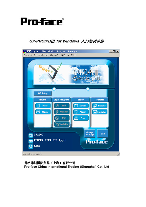
软件入门培训手册
2.2.2 通过网络传输 选择 [Ethernet] 设置目标 GP 的 IP 地址,Port(端口号):8000(固定值)
选择 [Ethernet:Auto Acquist] 在传输数据前,系统通过自动检查,显示出当前网络中已连接的 GP 的 IP 地址。选 择对应 GP 的 IP 地址,对其进行画面传输。
10
软件入门培训手册
[功能 (Function)] 位开关实现的功能有如下四种,请从中选择一种。 置位 (Bit Set):当开关被按下时,PLC 相应的位被置为 ON。(状态保持) 复位 (Bit Reset):当开关被按下时,PLC 相应的位被置为 OFF。(状态保持) 瞬动 (Momentary):当开关被按下时,PLC 相应的位被置为 ON,开关放开
2.2 画面传输方式
GP 画面有3种传输方式:电缆传输、CF 卡传输、网络传输。
2.2.1 通过电缆传输 选择 [COM] 口,设置传输速率。 在进行传输前在电脑和 GP 之间连接一根画面传输电缆(GPW-CB02 或 GPWCB03)口,传输设置如下图所示。
传输电缆一端接 GP 的 TOOL 口,另一端接电脑的 COM(CB02)或是 USB(CB03)口。 注意:用 CB03 传输时,要先在电脑上安装驱动程序。
4
指定要传 输的信息
选择传输 方式
指定传输 模式
离线状态下的 系统文字以及 设定信息文件 的位置
软件入门培训手册
选择下载 程序的通 讯端口
选择是否 使用模拟
◆ 通讯端口 (Communication Port) [COM]:使用传输电缆(GPW-CB02/GPW-CB03)下载程序时,选择对应的串 行口以及传输速率(波特率)。 如果是 GP2000 系列的触摸屏,传输速率最快可以达到115.2K。 [Ethernet]:输入IP地址和端口号。 [Ethernet:Auto Acquist]:自动搜索连接在网络中的GP的IP地址。
- 1、下载文档前请自行甄别文档内容的完整性,平台不提供额外的编辑、内容补充、找答案等附加服务。
- 2、"仅部分预览"的文档,不可在线预览部分如存在完整性等问题,可反馈申请退款(可完整预览的文档不适用该条件!)。
- 3、如文档侵犯您的权益,请联系客服反馈,我们会尽快为您处理(人工客服工作时间:9:00-18:30)。
一:PolSARpro读取雷达数据
S1:选择雷达类型,如下图,以radarsat-2为例;
S2:设置RADAR数据读取路径,保存退出,特别注意一定要设置为直
接存储RADAR数据的子文件夹,可能会出现以下提示,点击YES继续。
S3:点击Import——Input Data File,出现如下对话框,设置输出
路径,点击SAR Product File——Open File,转到之前设置的RADAR
数据所在文件夹——选择product——Read Header读取图像信息
——OK。
S4:Import——Quick Look, 就出现了所加载的数据,也可以选择
Extract裁剪数据。