江苏大学毕业设计
毕业设计过程指导记录

江苏大学毕业设计(论文)指导记录
题目鉴于的航空订票系统设计与开发
学号姓名重新霞专业计算机科学与技术班级13计本1
指导教师姓名石鲁生指导教师职称副教授
学生填写指导老师填写
日期指导记录进度状况署名
和指导老师议论论文选题,说出自己的想法,综合老师建议
确立选题。
指导查阅、采集有关课题资料。
向指导老师报告采集对于计算机网络的资料和文件,
并说明问题。
导师介绍毕业设计开题报告的格式和有关注意事项。
导师指导改正开题报告等几个文档。
导游师讨教系统上碰到的问题,导师给出解决问题的方法
导游师演示达成的系统,我并针对导师提出的优化建议进行改正。
注:1、学生应仔细、规范填写教师指导状况;2、指导老师进度状况填写:正常、偏慢等评论;3、原则上每周指导一次,记录不低于十次。
日期指导记录进度状况署名
导游师演示改
正后的系统,并确立系统最后版。
导师规划论文的写作计划,确立在5月初提交论文草稿。
导师对论文草稿提出改正建议,并在论文的行文和思想表达上赐予改正建议。
导师针对论文中的不规范处仔细标明,并解说怎样改正。
导师对第二稿论文提出改正建议,图表规范不符需改正。
导师对第三稿论文提出改正建议,对文中的详细
格式提出改正建议,如行距、字号等。
导师针对辩论PPT进行提出改正建议,字体有点小、
字体有点小、截图分类展现。
导师贴心准备预辩论,并讲了辩论的注意事项。
注:1、学生应仔细、规范填写教师指导状况;2、指导老师进度状况填写:正常、偏慢等评论;3、原则上每周指导一次,记录不低于十次。
餐饮空间毕业设计

餐饮空间毕业设计篇一:餐饮空间毕业设计论文(环艺室内设计毕业论文)江苏大学艺术学院本科毕业论文特色概念在餐饮空间中的应用学生所在系(院)艺术学院专业(方向)艺术设计(环境艺术)年级姓名学号 3091809016指导教师姓名李晓完成时间: 20xx 年 3 月目录摘要、关键词...........................................01 引言...................................................02 1“玩着吃”设计概念的由来和特点. (02)1.1 “玩着吃”概念的由来 (02)1.2 “玩着吃”概念的两个特点 (02)1.3 “玩着吃”概念对消费者消费心理的把握................03 2“玩着吃”概念在毕业设计手段上的体现. (03)2.1 空间造型体现出的趣味性 (03)2.2 空间的划分 (05)2.3 空间装饰设计 (05)2.4 空间动线的“欲擒故纵” (06)2.5 空间中照明系统设计 07 3对餐饮空间设计未来展望.............................08 总结...................................................08 参考文献.. (09)摘要:毕业设计小组通过对国内外餐饮空间设计现状的分析,在毕业设计中提出了“玩着吃”的设计概念,在论文中对概念的定位和特点进行描述,以及对消费者消费心理的研究。
从空间造型设计、空间划分、立面装饰的设计、空间动线、照明系统设计五个方面出发,来探讨“玩着吃”概念在设计手段上的体现。
并对餐饮空间设计前景初步分析。
关键词:餐饮空间;设计概念;趣味性;设计手段引言:餐饮文化具有悠久的历史,它的发展历程是一个国家、一个民族的发展史中不可分割的一部分。
不论是在中国还是其他国家,餐饮业的形成和演变都与人类生活紧密相连,它往往涉及经济活动、宗教信仰、地理环境、民族文化等。
江苏大学开题报告模板

学生毕业设计(论文)开题报告
一、基本情况
课题
情况
课题名称
课题来源
开题时间
计划完成时间
课题承担人(学生)情况
学生姓名
性别
在读学历
入学时间
毕业时间
所学专业
指导教师情专业
主要教学任务
研究方向
注:课题来源指自选课题,还是项目课题。项目课题课题要注明项目的名称及来源。
论文各阶段内容
日期
六、审核意见
1、指导教师审核意见
指导教师签字:
年月日
2、专业教研室主任审批意见
教研室主任签字:
年月日
二、课题的背景分析(课题所涉及问题在国内外的研究现状综述)
三、课题的研究价值(课题的价值及实际指导意义)
四、课题的实施方案
1、课题的主要论点和拟采用的研究方法
2、课题的研究重点、关键及解决的思路
3、课题的预期成果
4、开展课题研究拟搜集的资料、主要参考文献、实验设备的支撑及解决方法
五、课题的进程安排
序号
江苏大学机械毕业设计外文翻译

江苏大学机械毕业设计电磁阀外文翻译附录Ⅰ:Magnetoelastic Torque Sensor Utilizing a Thermal Sprayed Sense-Element for Automotive Transmission ApplicationsBrian D. KilmartinSiemens VDO Automotive Corporation ABSTRACTA Magnetoelastic based Non-Contacting, Non-Compliant Torque Sensor is being developed by Siemens VDO for automotive transmission applications. Such a sensor would benefit the automotive industry by providing the feedback needed for precise computer control of transmission gear shifting under a wide range of road conditions and would also facilitate cross-platform usage of a common transmission unit.Siemens VDO has prototyped transmission torque sensors operating on the principle of Inverse- magnetostriction, also referred to as the Inverse-Joule Effect and the Villari Effect. Magnetostriction, first documented in the mid 1800’s, is a structural property of matter that defines a m aterial’s dimensional changes as a result of exposure to a magnetic field. Magnetostriction is caused when the atoms that constitute a material reorient in order to align their magnetic moments with an external magnetic field. This effect is quantified for a specific material by its saturation magnetostriction constant, which is a value that describes a material’s maximum change in length per unit length.Inverse-magnetostriction, conversely, defines changes in a material’s magnetic properties in response to applied mechanical forces. Material that is highly magnetostrictive and elastic in nature is referred to as being magnetoelastic. The premise of the Siemens VDO torque sensor design is that a magnetoelastic material can be bonded to a cylindrical shaft and magnetized in its mechanical quiescent state to create a sense- element. While under torque, principle tensile and compressive stress vectors in the form of counter- spiraling, mutually orthogonal helices develop in the shaft and are conveyed to the magnetoelastic sense-element giving rise to a measurable magnetic field change. The magnetic field deviation that arises from the magnetoelastic sense-element is directly proportional to the magnitude of the imposed torque. In effect, the magnetic field is modulated by torque. A sensitive magnetometer then translates the field strength into an analog voltage signal, thereby completing the torque-to-voltage transducer function.Critical to the success of the Siemens VDO torque sensor design is an intimate attachment of the sense- element to the torque-bearing member. Inconsistencies in the boundary between the sense-element and the torque-bearing member will result in aberrant coupling of stresses into the sense-element manifesting in performance degradation. Boundary inconsistencies can include such imperfections as voids, contaminates, lateral shearing, and localized zonesof stress pre-load. Such inhomogeneities may be inherent to an attachment method itself or may subsequently be caused by systemically rendered malformations.Thermal spray, the process where metal particles are deposited onto a substrate to form a coating, was used to address the issue of securely affixing magnetic material to a torque-bearing member. In addition to achieving the prerequisite of an intimate and secure bond, the thermal spray process can be regulated such that the deposited magnetic material is pre-loaded with the internal stresses needed to invoke the inverse- magnetostriction effect.Summarizing, the passive nature of the magnetic sense- element provides an intrinsically simple kernel for the Siemens VDO torque sensor that makes for a highly reliable and stable design. The thermal spray process adds robustness to the mechanical aspect by permitting torque excursions to an unprecedented ±2000% of full scale (per prototype validation testing of certain constructs) without the need for ancillary torque limiting protection devices. Furthermore, accuracy, repeatability, stability, low hysteresis, rotational position indifference, low cost and amenability to the high-volume manufacturing needs of the automotive marketplace are all attributes of this torque sensing technique. When coupled with a magnetometer that is grounded in well- established fluxgate technology, the resultant sensor is inherently dependable and can potentially establish a new standard for torque measuring sensors.INTRODUCTIONAs is well known, automotive transmissions are designed to alter the power transfer ratio between the engine and the drive wheels effectively optimizing engine loading. The engine thereby runs in a narrow and efficient operating band even though the vehicle travels over a wide range of speeds. For automatic transmissions, shift valves select the gear ratio based generally on the throttle position, engine vacuum and the output shaft governor valve state. With the advent of electronic sensors and computerized engine controllers, transmission shift functions have been migrating towards closed-loop operation under software processing control. Along with this progression came the realization that the transmission output torque would provide a valuable feedback parameter for shift and traction control algorithms. The measurement of output torque, however, proved elusive due to the extremely harsh operating conditions. One particular SUV application under consideration required 1% accuracy in measurements of roughly 2700 Nm with possible torque excursion of 4700 Nm; all while exposed to temperature extremes -45 to +160 o C.One method for measuring torque is to examine the physical stresses that develop in a shaft when it is subjected to an end-to-end twisting force. The principle stresses are compressive and tensile in nature and develop along the two counter-spiraling, mutually orthogonal 45 o helices. They are defined by the equation :t = Tr / JWhere T is the torque applied to the shaft, r is the shaft radius and J is the polar moment of inertia.Setting p r4/ 2 = J for a solid cylindrical shaft and r = d/2 yields:t = 16T / p dOnce again, T is the torque applied to the shaft and d is the shaft diameter.Furthermore, the degree of twist experienced by the shaft for a given torque is given by2: q = 32(LT) / (p d4G)Where L is the length of the shaft, T is the applied toque, d is the diameter of the shaft and G is the modulus of rigidity of the shaft. The modulus of rigidity defines the level of elasticity of the shaft material, thus, a lower G value would manifest in a shaft with a higher degree of twist for any given applied torque.Torque induced stresses that occur in the shaft material are transferred into an affixed magnetic coating and give rise to measurable changes in its surrounding magnetic field that are directly proportional to the magnitude of the applied torque; with the polarity of the magnetic field, i.e., north or south, governed by the direction of the applied torque. In essence, this is the premise of torque sensing by means of inverse magnetostriction.TORQUE SENSOR EMBODIMENTTo effectively invoke the inverse-magnetostriction effect, the magnetic material must be correctly pre-loaded with stress anisotropy in its quiescent state. In the case of a cylindrically shaped magnetic element, the anisotropic forces must be circumferential (i.e., tangential) in nature and can be either compressive or tensile –depending on the polarity or sign of the material’s saturation magnetostriction constant. Achieving a homogenous pre-load throughout the magnetic material is crucial if the sensor is to accurately interpret torque regardless of its rotational position within a stationary magnetometer.POSITIVE MAGNETOELASTIC DEVICESEarlier efforts to create such a torque sensing element relied on a sense element made of material with a positive saturation magnetostriction constant. This embodiment was realized with a ring-shaped magnetoelastic element made from 18% nickel-iron alloy that intrinsically requires tensile circumferential pre- loading 3 . Such a pre-load was achieved by pressing the ring onto a tapered area of the base shaft – effectively stretching it. The effect of tensile stress on the magnetic hysteresis behavior is shown in Figure 1 where the remnant inductance, B r , nearly triples. The “easy-axes” of the magnetic domains align circumferentially due to the anisotropy defined by the principal tensile stress vector. When magnetically biased, the system in effect operates as a circumferentially shorted magnet with B approaching B r and H approaching zero.NEGATIVE MAGNETOELASTIC DEVICESTo advance the state of the art, Siemens VDO Automotive has opted for a magnetoelastic element witha negative saturation magnetostriction constant. In this case, the alloy is very high in nickel content exhibiting a saturation magnetostriction, l s , in the range of -3e-5 dl/l and requires the stress pre-load to be tangentially compressive in nature. To achieve this embodiment, the magn etoelastic material that constitutes the sense element is “deposited” onto the base shaft using a high- velocity-oxygen-fuel (HVOF) thermal spray process. The coating thickness is only 0.5mm with an axial length of 25mm. The sense element material is endowed with compressive stress by means of precise control of the thermal spray process parameters. This proprietary procedure transforms a deposition process that normally confers isotropic material properties into one that renders the requisite stress anisotropy.Prototype FabricationMagnetoelastic ElementThe specification for the shaft requires the measurement of torque levels of 2700 Nm with no deleterious effects following exposures of up to 4700 Nm. Operating temperature is -45 o C to 160 o C.By c onverting from the earlier torque sensor “pressed-on ring” concept to one based on a magnetoelastic material with a negative saturation magnetostriction constant, l s , the design is advanced in several respects. Primarily, its resiliency against stress/corrosion cracking is enhanced by 1) the inherent insusceptibility of high nickel content alloys towards corrosives and 2) by the lower porosity of material in compression. This is in distinct contrast with the high iron content ring placed in tension which is vulnerable to fissuring, material creep and stress corrosion cracking which can, over time, relieve the necessary anisotropic forces causing performancedegradation.An important consequence of using the thermal spray technology is the intimate bond provided between the deposited magnetoelastic element and the base shaft. By using a thermal spray process, the boundary whereby torque induced stresses are transferred is free of such imperfections as voids, galled or furrowed material and localized stress gradients that are all characteristically associated with the pressed-on ring technique. These imperfections can induce aberrations in the magnetic field shape thereby imparting torque measurement errors relative to the rotational position of the shaft with respect to a stationary magnetometer. Furthermore, the strong bond at the interface effectively eliminates the slippage commonly associated with the interference fit of a pressed-on ring during extreme torque exposures. Any movement at this interface will manifest as a biasing of material stresses causing a zero-shift measurement error. This is not a concern when the magnetoelastic element is deposited using an HVOF thermal spray gun. Torque excursions to an unprecedented ±2000% of full scale have been successfully applied directly to prototype sensors without ancillary torque limiting protection devices.In addition, depositing the magnetoelastic element onto a rotating shaft provides an inherently mechanically balanced assembly that imposes no angular velocity (RPM) or angular acceleration limits on the system.Other thermal spray technology attributes are its amenability to high volume manufacturing environments, the robustness of the process insuring consistent reproducibility, and an overall reduction in fabrication steps –such as the elimination of machining procedures to mass-produce rings, cutting operations for precisely matching tapers on the shaft and ring, and pressing operations to install rings onto shafts.Magnetic Field ShapingContributions from the mechanical mounting tolerances of system components (e.g., bearings and bushings) can manifest as a misalignment between the centroid centerlines of the magnetometer and the magnetoelastic element. Once calibrated, any displacement in the positional relationship between these two components will alter the system’s transfer function, possibly causing the overall error to exceed specification. The sharply focused nature of the magnetic field radially emanating from the magnetoelastic element during the application of torque (see Figure 3) accentuates this effect. This error can be minimized by shaping the physical structure of the magnetoelastic element resulting in a contouring of the magnetic field to a more favorable shape. As shown in Figure 4, the magnetic field is made to be less pronounced with an hourglass shaped magneto elastic element and sensitivity to misalignment is, thus, reduced. In this example, the magneto elastic element is contoured such that the air gap between the magneto elastic element and the magnetometer is reduced when axial displacement between their centroid centerlines occurs. The expected reduction in magnetic signal strength caused by this displacement is thus compensated by the air gap reduction.Shafts can be fabricated with a variety of contoured surface adaptations and the thermal sprayed magnetoelastic element’s shape will expectedly follow suit. As is evident, a pressed-on ring manifestation of the magnetoelastic element would be incompatible with this technique. Various contours are being considered for further reducing the sensitivity to misalignment and for improving other performance parameters such as magnetic field strength and hysteresis.Cylindrical Shaft Shown with Superimposed Associated Magnetic Field (i.e., Radially Directed Flux Density)Contoured Shaft (Hourglass Shape) Shown with Superimposed Associated Magnetic Field (i.e., Radially Directed Flux Density)In Figures 3 and 4, the spatial image of the shaft is mapped using a laser displacement system and the superimposed magnetic field is mapped in 3-space with a hall cell.MagnetometerRounding out the torque sensor hardware complement is a non-contacting magnetometer that translates the magnetic signal emitted by the shaft’s sense element into an electrical signal that can be read by system-level devices. Coupling the torque signal to some interim conditioning electronics magnetically is an attractive op tion due to its “non-contacting” attribute. A signal transference scheme capable of spanning an air gap is advantageous sinceit requires no slip rings, brushes or commutators that can be affected by wear, vibration, corrosion or contaminants.The fundamental magnetometer embodiment, shown in Figure 5, is circular with the shaft passing through its center. The magnetometer encompasses the magnetoelastic element of the shaft and the shaft is allowed to freely rotate within the fixed magnetometer. Power and the output signal pass through the magnetometer’s wiring harness.Transmission Torque Sensor MagnetometerThe magnetometer actually performs several functions beyond measuring a magnetic field’s strength. These functions include magnetic signal conditioning, electrical signal conditioning, implementation of self-diagnostics, and the attenuation of magnetic and electromagnetic noise sources.The magnetic detection method chosen for the torque sensor is fluxgate magnetometry, also known as saturable-core magnetometry. This is a well-established technology that has been in use since the early 1900’s. Fluxgate magnetometers are capable of measuring small magnetic field of strengths down to about 10 -4 A/m (or 10 -6 Oe) with a high level of stability. This performance is roughly three orders of magnitude better than that achieved by Hall Effect devices. Although many fluxgate designs use separate drive and pickup coils, the torque sensor magnetometer was designed to use a single coil for both functions.Magnetic signal conditioning is accomplished by use of flux guides integral to the magnetometer. These flux guides amplify the magnetic signal radiating from the shaft’s sense element prior to detection by the fluxgates thereby improving the signal-to-noise ratio. The flux guides provide additional signal conditioning by integrating inhomogeneities in the magnetic signal relative to the shaft rotational position that might otherwise be misinterpreted as torque variations. The flux guide configuration is shown in Figure 6 and a magnetic simulation of the resulting field concentration is shown in Figure 7.Flux guides surrounding magnetoelastic elementAxial view of magnetic simulation with flux guide material’s relative DC permeability set to 50,000 (e.g., HyMu “80”)To further improve the magnetometer’s immunity to stray signals present in the ambient, common-mode rejection schemes are employed in the design of both the electronic and magnetic circuits. For example, wherever possible, differential circuitry was used in theelectronic design in order to negate common-mode noise. This practice was carried over to the magnetic design through the use of symmetrically shaped flux guides and symmetrically placed fluxgates that cancel common- mode magnetic signals that originate outside the system.Finally, to augment the electrical and magnetic common- mode rejection strategies, EMI and magnetic shielding practices were incorporated into the design to further improve the signal-to-noise ratio. Stray magnetic and electro-magnetic signals found in the ambient are prevented from reaching the fluxgates and the shaft’s magnetic torque-sensing element through the use of shielding material that encompasses these critical components.The functional diagram of Figure 8 depicts the concept of the magnetometer by showing a simplified version of the circuitry with extraneous components removed for additional clarity. An application specific integrated circuit (ASIC) contains all the circuitry necessary to perform the indicated functions.Magnetometer Functional DiagramSummarizing, the multi-function, fluxgate based magnetometer design provides the optimal platform for detecting the modulated magnetic field that emanates from the shaft’s torque-sensing magnetic element. By coupling time-proven fluxgate technology with an innovative flux guide configuration and with sophisticated electronic circuitry, the resultant magnetometer is durable, accurate, and stable and comprehensively achieves the design goals dictated by the application.CONCLUSIONThe latest developments in the magnetoelastic torque sensor that are presented here advance the current state of the technology by addressing many obstacles that have delayed itsacceptance by the automotive industry. Thermal spray deposition of the magnetoelastic element has resolved problems that have plagued earlier versions of the magnetoelastic torque sensor’s active element. The lack of integrity of the shaft/magnetoelastic element interface, stress-corrosion cracking, long term stability, inhomogeneity of magnetic properties and manufacturing processes that run counter to high volume production, are no longer hindering the introduction of magnetoelastic torque sensors into the automotive marketplace. With design goals clearly defined and an aggressive development program invariably progressing, the prospect of an automotive, magnetoelastic based non-compliant torque sensor is now more readily attainable.ACKNOWLEDGMENTSI would like to acknowledge the efforts of Ivan Garshelis who pioneered this approach to torque sensing and who had the unwavering vision to recognize this technology’s potential; and Carl Gandarillas whose scientific and analytical investigative approach has explicated much of the mystery associated with thermal sprayed magnetics. I would also like to express my gratitude to the torque sensor development team at Siemens VDO Automotive for their dedication and the extra effort that they put forth; and to Siemens VDO Automotive management for having the courage to invest in a new technology and the patience to see it through.REFERENCES1. Raymond J. Roark and Warren C. Young, Formulas for Stress and Strain, 5 th Edition, McGraw-Hill; Chapter 9, Torsion2. Stephen H.Crandall and Norman C. Dahl, An Introduction to the Mechanics of Solids, McGraw-Hill; Chapter 6, Torsion3. Ivan J. Garshelis, Magnetoelastic Devices, Inc., IEEE Transaction On Magnetics ; 0018-9464/92 V ol. 28, No. 5 September 5, 1992ADDITIONAL SOURCES1. Richard L. Carlin, Magnetochemistry; Springer-Verlag2. Rollin J. Parker, Advances In Permanent Magnetism; John Wiley & Sons3. Etienne du Tremolet de Lachhesserie, Magnetostriction Theory and Applications of Magnetostriction; CRC Press4. Richard M. Bozorth, Ferromagnetism; IEEE Press附录Ⅱ:磁力矩传感器利用一个热喷涂感知元件在汽车变速器中的应用转载自:2003年发动机电子控制布赖恩D.基尔马丁西门子威迪欧汽车电子公司摘要一个非接触式的,非兼容扭矩的传感器是由西门子VDO正在开发应用于汽车传动之中。
20110江苏省大学生毕业设计评比结果
季进 涂小马 阮新波 陈松灿 刘冰 袁慎芳 左敦稳 陈柏 陆珩瑱 崔一平 徐青山 吴刚 滕玉明 舒赣平 罗翔、何农跃 王鑫 张东旭 沈雷 廖祖华 李晓钟 史明 蔡利梅 吴侃 朱真才 刘贞堂 林爱梅 郑源 陈卫 刘晓农 杜晓荣 赵洋 汪信、张树鹏 熊党生 杨孝平 王存德 徐辰武 焦富民 班吉庆 薄翠梅、崔咪芬 陈苏 金万勤 武文彬 孙钦伟 魏丰 张颖 荆晓远 杨震 傅海阳 勇强 周晓燕 林少华 王俊 裴星洙 杨松林 曹典顺 沙先一 王奇伟 刘贤兴  、 谭中明
臧晴 戴甄 杨洋 吴小燕 田博 刘沛沛 曾洁 王鹏 刘姗 宗慎飞 初祥祥 牛星 王其标 余冠群 何晓华 姜进 鞠晓辉 刘进 曹姝 何建莹 李萌 蒋超 赵鑫 马皖 杜中明 余蓉蓉 杨春霞 陈彬 包洪洁 胡婕 寇佳新 熊攀 杨慧 姬繁琼 耿鑫 闫成海 杨颖 许可 刘欣 张静 石磊 朱志刚 李大鹏 郝贵群 顾汉龙 李升 刘颖 陈技江 张丽 章蓉 何蕙君 马延龙 张文 崔健 吕文伟 叶平 赵庆淼 周真子 蒋小晴
张明宝
博济创业园虚拟仿真系统的设计与实现
樊明明
运用TRIZ理论设计2-氟-6-碘苯甲酸的合成方法
王玲
工程企业项目管理系统的设计与实现
郝春梅
女装设计——倾听
刘艳飞
废旧工业厂房区的景观化改造研究——常州运河五号改建工程
顾静
淮安市白酒市场细分变量与策略研究
王珊珊
无线传感器网络技术在设施农业智能化中的应用研究
曹周健
有限元建模在悬臂现浇梁桥施工质量监控中的应用设计 -------南京划子河大桥主桥
上部结构施工质量安全监控方案探索
朱礼成
滨河景观带设计
羊娟娟
中式寿宴设计与制作
李金龙
互动传媒《SOGO校园》消费资讯导航报创业计划书
毕业设计63windows 2000 sever 安全技术研究——防火墙技术

江苏大学毕业设计(论文)题目:windows 2000 sever 安全技术研究——防火墙技术院系:计算机科学与通信工程学院专业:通信工程年级:通信002班学生姓名:周亮指导老师:周莲英2 0 0 4 年0 5 月2 8 日摘要:本文在分析因特网网络安全问题、相应安全策略与安全机制以及安全攻击与黑客攻击的基础上,重点研究了基于windows 2000server安全策略的防火墙技术,包括防火墙的功能、分类、特点与局限性,以及防火墙的实现方式、发展趋势等等。
最后以某工厂网络重建为例,具体分析了两套网络构建方案,并对其中一套方案进行了安全设计及初步实现。
关键词:网络安全,安全策略,防火墙Abstract:This article studies the firewall technology according to windows 2000server’s security policies on the found of internet network security problems,corresponding security policies ,security mechanism ,security attack and hacker attack,including firewall’s functions,classification,characters,develop tendency and so onl.At the last,it uses a case of netwoek reconstruction of some factory,concretely analysises two proposals about network construction,then designs the security demandings and realizes them preliminary.Keywords:network security, security policy, firewall目录:第一章引言 (5)1.1I NTERNET 的发展及现状 (5)1.2I NTERNET所面临的威胁 (5)第二章计算机网络安全概述 (7)2.1网络安全的定义 (7)2.2安全攻击 (7)2.2.1 典型的攻击过程 (8)2.2.2 常用的攻击工具 (8)2.2.3 常用的攻击手段 (10)2.3安全服务、安全机制与安全策略 (12)第三章防火墙技术综述 (17)3.1防火墙的基本概念 (17)3.2防火墙的分类 (17)3.3防火墙的实现方式 (19)3.4防火墙的局限性 (21)3.5防火墙的发展趋势 (21)第四章某工厂网络重建与防火墙技术应用 (22)4.1网络安全与企业内部网 (22)4.2某工厂网络重建需求 (22)4.3设计原则 (22)4.4方案选择 (23)4.5防火墙配置 (26)第一章引言1.1 Internet 的发展及现状Internet起源于美国的ARPAnet计划,其目的是建立分布式的、存活力强的全国性信息网络。
2010年江苏省普通高等学校本专科优秀毕业设计(论文)评选获奖名单1
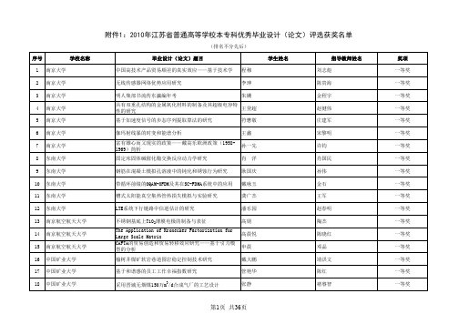
刘进
模糊与粗糙集研究:几类新的模糊正规子群
曹姝
FDI对我国高新技术产品出口竞争力影响分析
何建莹
城市更新建筑与景观设计—青岛小港湾滨海景观设计 李萌
基于改进模糊聚类的脑部磁共振图像分割方法研究与实 现
蒋超
学生姓名
第4页 共36页
指导教师姓名 阮新波 陈松灿 刘冰 袁慎芳 左敦稳 陈柏 陆珩瑱 崔一平 徐青山 吴刚 滕玉明 舒赣平 罗翔、何农跃 王鑫 张东旭 沈雷 廖祖华 李晓钟 史明 蔡利梅
朱礼成
滨河景观带设计
羊娟娟
中式寿宴设计与制作
李金龙
互动传媒《SOGO校园》消费资讯导航报创业计划书
周井
学生姓名
第2页 共36页
指导教师姓名 陈志强 范元勋 吕青、李彩霞 连冬花 唐洪武 施国庆 盛玉刚 丁彦芬 杨震 吴斌 刘承华 李金贵 王灿明、季燕 蔡建军、杜伟略 陆荣、奚小网 孙燕华、唐立平 王杰 张菲 陈金标 袁玉玲
顾静
淮安市白酒市场细分变量与策略研究
王珊珊
无线传感器网络技术在设施农业智能化中的应用研究 张浩
邳州城北污水处理厂工艺设计
丁肖立
钟摆式高楼自助逃生装置
刘啸
非圆对称部分相干平顶光束在大气湍流中的传输因子 丁 杰
汉语元音F1-F2共振峰结构及聚类特性分析、转换
朱春雷
RFI高性能双马来酰亚胺-三嗪环树脂复合材料的研究 廖凡
伽玛射线暴的时变和能谱分析
王鑫
富有雄心而又现实的政策——戴高乐欧洲政策(19581969)简析
孙一先
固定床固体碱催化酯交换反应动力学研究
肖洋
宋黎明 许钧 肖国民
钢筋在混凝土模拟孔溶液中的钝化和锈蚀行为研究
关于毕业生毕业设计期间外出实习的有关规定

关于毕业班同学毕业设计期间外出实习的有关规定
为使我院毕业生保质保量的完成毕业设计,规范毕业生毕业设计期间外出实习行为,特制定以下规定:
1、接收实习生的单位应具备提供毕业生做毕业设计所需的学习和工作条件,保证毕业生人生安全,安排具有毕业设计指导能力的工程师指导毕业生的毕业设计,达到江苏大学对毕业设计的要求。
若以上条件合部符合,实习单位应出具《毕业设计接收函》(附件1)。
2、准备外出实习的同学应填写外出实习《保证承诺书》(附件2),本人及家长签字后,连同实习单位出具的《毕业设计接收函》一同交给毕业设计指导老师审阅,毕业设计指导老师同意后即在外出实习《保证承诺书》上签字,然后由学生本人依次交给所在系主任、年级辅导员、教学院长签字同意后方可。
3、《保证承诺书》及《毕业设计接收函》均一式两份,由相关人员全部签字后分别交给学院教学秘书汪飞老师及年级辅导员各一份存档。
对不能严格按照规定擅自外出实习的同学,将给予相关处分,因此造成不能毕业的后果,责任自负。
江苏大学机械工程学院
二○一三年二月二十八日流程图:
-------。
- 1、下载文档前请自行甄别文档内容的完整性,平台不提供额外的编辑、内容补充、找答案等附加服务。
- 2、"仅部分预览"的文档,不可在线预览部分如存在完整性等问题,可反馈申请退款(可完整预览的文档不适用该条件!)。
- 3、如文档侵犯您的权益,请联系客服反馈,我们会尽快为您处理(人工客服工作时间:9:00-18:30)。
江苏大学毕业设计篇一:江苏大学本科生毕业设计(论文)写作规范南通大学毕业设计(论文)写作规范一、编写要求毕业设计(论文)文稿必须用A4(210mm*297mm)白纸打印。
打印时,要求纸的四周留足留足空白边缘,以便装订、复印。
每一页上方(天头)和左侧(订口)分别留25mm,下方(地脚)和右侧(切口)分别留20mm。
毕业设计(论文)一律左侧装订。
二、毕业设计(论文)的内容构成:封面序或前言(必要时)摘要前置部分关键词目次页插图和附表清单(必要时)符号、标志、缩略词、首字母缩写、单位、术语、名词等注释表(必要时)引言1章2章条)2.1.1(款)项)正文主体部分章结论致谢参考文献附录A附录部分附录B(必要时附录C(一)前置部分1.封面:封面包括设计(论文)题目、学院名称、专业班级、学生姓名、指导教师姓名及职称等几项内容。
(1)题目: 设计(论文)题目应该用简短、明确的文字写成,通过标题把平面设计(论文)的内容、专业特点概括出来。
题目字数要适当,一般不超过30个字。
如果有些文句必须放进标题,为避免冗长,可以设副标题,把细节放在副标题里。
(2)学院名称、专业班级、学生姓名、指导教师姓名及职称等几项内容填写。
2.目录:目录是毕业设计(论文)的篇章名目,要按顺序写清楚设计(论文)构成部分和章、节的名称。
建议列至二级目录。
3.摘要:是论文的内容不加注释和评论的简短陈述。
摘要应正当性具有中立性和自含性,即不阅读论文的全文,就能获得必要的内部信息。
摘要中有数据、有结论,是一篇完整的短文,可以独立使用。
网络版应说明研究工作目的、实验方法、结果和最终结论等,重点是结果和结论。
中文摘要一般不少于400字;外文摘要不少于350个实词。
如遇特殊需要,字数可略多。
摘要中一般不用图、表、化学结构式,非公知公用的符号和术语。
4.关键词:关键词是中文献标引工作从论文为了选取出的以表示全文主题内容信息款本意单词或术语。
每篇论文选取3-8个词作为关键词,以显著的字符另起一行,排在摘要的右下角。
尽量用《汉语主题词表》等词表提供支持的规范词。
关键词之间空二格。
(二)主体部分1.引言:简要说明研究工作的目的、范围、相关领域的前人工作和知识空白、理论基础和分析、研究设想、研究方法和实验设计、预期结果和意义等。
2.正文:正文是作者对研究工作的详细表述。
其内容包括:问题的提出,基本观点,解决问题的基本分析方法,必要的数据和图表,以及通过研究得出的结果与对展开讨论结果的讨论等。
正文字数一般为1万—1.5万左右,但对具有独特份量见解的论文不限篇幅。
(1)文中所用的符号、缩略词、坎奇斯规范和计量单位,必须遵照国家规定的标准或本学科通用标准。
采写自己拟订的符号、记号缩略词,均应在第一次出现时加以说明。
(2)图:毕业设计(论文)中的图包括曲线图、构造图、示意图、图解、框图、流程图、记录图、布置图、地图、照片、图版等。
所有的图应编排序号,序号一律用阿拉伯数字分别依序连续编排。
如图1、图2??,每一图应有简短完全相同相符的题名,连同图号置于图下。
(3)表:所有的表应编排序号,序号一律用阿拉伯数字分别依序连续编排。
如表1、表2??。
每一表所刻应有意味深长确切的题名,连同表号置于表上。
必要时,应将表中的符号、标记、代码以及能够说明事项,以最简练的文字,横排于表题下,作为表注,也可以附注于表下。
表内同一栏的表情符号必须上下对齐。
表内不能用“同上”、“同左”“;”和类似词,一律填入具体的数字插入或文字。
(4)数学、物理和化学式毕业设计(论文)中的公式、算式或方程式等一律用阿拉伯数字分别依序连续编排,序号标注于该式所在行(当有续行时,应标注于最后随同)的最右边。
(5)计量单位:毕业论文中的量和单位以国际单位制(SI)为基础,必须符合中华人民共和国的国家标准GB3100~GB3102-93。
非物理量的单位,如件、台、人、元等,可用汉字希腊字母与符号构成组合形式的单位,例如件/台、元/km。
(6)标题层次毕业设计(论文)的全部副标题层次应统一、有条不紊,整齐清晰,相同的层次应采用统一完全相同的表示体例,正文中各级标题下的内容应同各自的标题对应,不应有与标题无关的文本。
章节编号方法应采用分级阿拉伯数字编号方法,第一级为“1”、“2”、“3”等,第二级为“2.1”、“2.2”、“2.3”等,第三级为“2.2.1”、“2.2.2”、“2.2.3”等,但分级阿拉伯数字的编号一般不超过四级,公办民助之间用下角圆点隔开,每一级的末尾不加标点。
3.结论结束语包含对整个研究工作适用于进行归纳和综合而得到的结论,以及对问题的进一步探讨的设想与建议。
4. 致谢:通常以简短的文字对在课题研究与论文撰写过程中直接给予帮助的指导教师、答疑教师和其他人员表示自己的谢意。
在结论后单置一页。
5.参考文献参考文献是毕业设计(论文)不可缺少的组成部分,它反映林宏吉毕业论文的取材来源、材料的广博程度和材料的可靠模具程度,也是作者对他人知识成果的承认和尊重。
一份完整的资料是向读者提供的一份有价值的信息参考文献。
参考文献著录规则:(1)专著的著录项目、著录格式及著录用符号:主要责任者.书名[文献类型标识].其他责任者.版本.出版地:出版者,出版年.文献数量.丛编项.附注项.文献标准编号其中,主要责任者、书名、版本、出版地、出版者、出版年为必须著录房地产项目,其他为选择项目。
参考文献类型,根据GB3469-83《文献类型与文献载体代码》规定,以单字母方式标识:M―专著,C―论文集,N―报纸文章,J―期刊文章,D―学位论文,R―研究报告,S―标准,P―专利;对于专著、论文集中的析出文献采用单字母“A”标识,其他未说明的文献种类,采用单字母“Z”标识。
例:刘少奇.论共产党员的修养.修订2版.北京:人民出版社,1962.76页(2)连续出版物的著录房地产项目、著录格式及著录用符号:题名.主要责任者.版本.年.月,卷(期)~. 年.月,卷(期).出版地:出版者,出版年.丛编项.附注项.文献标准编号其中,题名、主要责任者、版本、出版地、出版者、出版年为必须著录房地产项目,其他为选择项目。
例:地质评论.中国地质学会.1936,1(1)~.北京:地质出版社,1936.~(3)专著投资项目中析出的史料著录项目、著录格式及著录用符号:析出责任者.析出题名.析出其他责任者.见:原文献责任者.原文献题名.版本.出版地:出版者,出版年.在将原文献中的位置其中析出责任者、析出题名、见:原文献责任者、原文献题名、版本、出版地、出版者出版年、在原文献中的位置为必须著录项目,析出其他责任者为选择项目。
例:黄蕴慧.国际矿物学研究的动向.见:程裕淇等编.世界地质科技发展战略动向. 北京:地质出版社,1982.38~39(4)连续出版物中析出的文献的著录项目投资、著录文件格式及著录用符号:析出责任者.析出题名.析出其他责任者.原文献题名,版本.在原文献中的环上其中析出责任者、析出题名、原文献题名、版本、在原文献中的位置为必须著录项目,析出其他责任者为选择项目。
例:李四光.地壳构造与地壳运动.中国科学,1973(4):400~429参考文献例:[1].中国科学院南京土壤研究所西沙群岛.我国西沙群岛的土壤和鸟粪矿.北京:科学出版社,1977[2].傅承义,陈运泰,祁贵中.地球物理学基础.北京:科学出版社,1985.477[3].华罗庚,王元.论一致分布与近似统计分析:数论方法(Ⅰ).中国科学,1973(4):339~357[4].赵均宇.略论戊戌变法前后的章太炎.光明日报,1977 03-24(4)(三)附录部分第一卷项目作为论文主体的补充项目,可包括某些关键重要的电脑系统、数学推导、计算程序、框图、结构图、注释、统计表、计算机打印输出件等。
附录的序号编排按附录A、附录B...编排,附录(以附录B为例)内的顺序可按B2,B2.1,B2.1.1,B2.1.2的规律编排。
图表按:图B1,图B2,表B1,表B2的规律编排。
附录与正文手抄在一起,连续编页码。
三、毕业(设计)论文的写作细则:打印排版格式如下1、封面页:采用学校教务处规定的统一山东师范大学格式(样式见附录1)中文论文题目用二号黑体,可以分为1或2行居中打印;英文论文题目用16pt Time New Roman,Bold;学院名称、专业班级、学生姓名、指导教师姓名、指导教师职称用四号宋体。
2、目录页:(样式见附录2)(单独成页)清单二字用二号黑体,居中,段前段后间距为1行;一级目录用四号宋体;二级目录用小四号宋体;页码放在行末,目录内容和页码之间用箭头连接。
3、题目、摘要和关键词:(样式见附录3)(单独成页)题目:毕业设计(论文)题目为三号小写,可以分1或2行居中打印;论文(设计)题目下空一行考题打印专业班级、学生姓名、指导教师、职称内容,用小四号宋体。
摘要:题目下空一行打印概要,摘要二字用四号黑体,摘要二字后空一格打印内容用小列印四号宋体关键词:摘要内容下空一行打印关键词,关键词三字用四号宋体,其后为关键词内容,用小四号宋体,每两个基本要素之间空二格。
英文题目、摘要、关键词内容则应与并不相同中文相同。
打印时全部采用小四号Arial字体,摘要内容和关键词内容均用十一号一号Arial字体。
英文题目、摘要、关键词合打一页(样式见附录3)。
4、正文:采用小四号宋体字打印。
行间距为1.5倍行距。
(样式见附录4)5、正文用小四号宋体字打印(若有标题用四号黑体字)。
6、标题:每章标题以四号黑体字居中打印;“章”下空一行为“条”,以四号宋体字左起打印;“条”下空一行为“款”,以小四号宋体字左起打印。
7、文中图、表应有自明性。
图、表名应附相应的英文和必要的中文图注。
制图要求:半栏图宽≤7cm,通栏图宽≤16cm;图中抛物线粗细应相当于5号宋体字的竖画,参考点线的粗细相当于5号宋体字的横画;图中文字、符号、纵横坐标标目用小五号字;标目采用国家标准的篇二:江苏大学毕业论文本科毕业论文镇江市文化路道路渠化设计Channelization Design of XueFu Road In ZhenJiang学院名称:汽车与交通工程___ _专业班级:交通工程0802_____学生姓名:陈丰______ __指导教师姓名:唐良______ __指导教师职称:讲师/博士____ __2021年05月摘要本文大多内容内容是对学府路的渠化设计,通过对学府路的实地调查,研究。
对学府路存在的客观存在一些问题进行改善设计。
主要包括以下几个方面:(1)依据道路渠化国内外研究现状及基础知识,从机动车流、非机动车车流和行人流三个方面分析其交通流特点。
(2)探讨了大型平面交叉口渠化措施,结合学府路-谷阳路交叉口实际交通流特点,对于机动车流,进行了交通渠化,以提高交叉口的通行能力;对于非机动车流,提出了设置自行车专用道,以减少机非冲突;对于行人流,提设置行人过街绿化带,以保证路口行人过街安全管理。