Product Configuration_V1.0
最新QXDM及QCAT软件使用入门指南V1.0
ZTE Diagnostics Interface 6000 (COM6) ZTE NMEA Device (COM7) ------------(数据卡) 6、打开QXDM软件,选择相应端口,如下图。
© 2006, ZTE Corporation. All rights reserved.
按上图步骤,选择与设备管理器中信息“ZTE Diagnostics Interface 6000 (COM6)”对应的COM 端口,最上方显示“COM6: SURF6280”等字样表示软、硬件已经设置好,可以开始使用QXDM软件。
16、分析HSDPA业务常用窗口及消息
© 2006, ZTE Corporation. All rights reserved.
1、如何打开MF330数据卡的调试口?-(1)
(1)将数据卡插入笔记本电脑的PCMCIA插槽,右击:我的电脑-管理-设备管理器,如上图
目前的新卡都关闭了此功能,需要借助at命令打开调试口,便于使用QXDM查看终 端侧信令,需先安装好数据卡驱动程序。
© 2006, ZTE Corporation. All rights reserved.
1、软件安装顺序:QPST -> QXDM -> QCAT。 2 、安装完成后,需要拷贝最新的 License 文件到 QXDM 、 QCAT 安装程序的 bin 目录 下,License文件给出了软件的有效使用日期起止时间。 3 、使用 F866 手机或高通手机需要安装 USB 驱动程序: hm11-v3865-18_2.0.22 ,接 好数据线后,让电脑自己找驱动安装;使用MF330数据卡需要安装拨号软件+驱动程 序:PC_P663M1V1.0.2B01 (注:随着版本升级,上述驱动及软件名称会有变化)。 4、上述软件及驱动可在W系统测试部部门园地上下载。 5、通过USB数据线或者PCMCIA插槽连接好硬件后,右键点击:我的电脑-管理- 设备管理器,右侧属性栏“端口(COM和LPT)”项应该出现下面类似硬件信息: Qualcomm Diagnostics Interface 3197 (COM6) Qualcomm Proprietary USB Modem (PID 3197)#2 --(终端)
DSI Setup和调试指南v1.0说明书
DSI Setup and Debugging Guide v1.0Kyle Rakos October 10, 2019 ContentsDSI Overview (2)DLPC343x Setup (3)DSI Configuration Requirements (5)DSI Configuration Settings (5)DSI Timings (6)Additional DSI Considerations (7)Example DSI Configuration and Timings (8)Qualcomm Specifics (9)DSI Waveforms (10)Nominal: Entire Video Frame (10)Nominal: Video Transmission (11)Incorrect: LP during HSYNC (12)Incorrect: Data always in HS Mode (13)Incorrect: Clock enters LP Mode (14)Nominal Timings (15)Debugging Checklist (17)Additional Resources (19)IMPORTANT NOTICE AND DISCLAIMER (20)Note: The information in this document is not a substitute for the specifications listed in the corresponding device datasheets. In the event of a discrepancy, the datasheet supersedes this document.DSI OverviewDSI (Display Serial Interface) is a source synchronous, high speed, low power, differential video interface. The DLPC3430 and DLPC3433 (both a part of the DLPC343x family) support the DSI Type-3 LVDS video interface with up to 4-lanes. DSI is a useful alternative to a parallel interface if a reduction in data lanes is desired. This can be useful to save space in a PCB (printed circuit board) layout, or it can be useful if a desired front end processor has a reduced pin count that only supports DSI video.Figure 1: OverviewThere are two main transmission modes: differential HS (high speed) mode and single-ended LP (low power) mode. HS mode is used to transmit video data. LP mode is used to send commands or enter a power savings mode. The DLPC343x has specific requirements of when these various modes are allowed. For additional specification details visit . A summary of the modes as implemented on the DLPC343x follows:∙LP mode: Signal level is 1.1V (1.2V if VDDLP12 is not tied to VDD) single ended and the clock lane is not used to decode the data.∙LP11: A low power state when both data lanes (e.g. DD0n and DD0P) are set high.∙HS mode: Signals are 200mV LVDS DDR (low-voltage differential signaling double data rate) and the clock lane is used to decode the data.∙Note that a set of LP states are commanded (LP11 -> LP01 -> LP00) to transition from LP mode to HS mode. This transition will automatically enable a terminating resistor in the DLPC343xcontroller. If the termination resistor is not enabled a 400mV signal will be seen on the datalanes. During nominal operation this should never occur.The DLPC3430 and DLPC3433 controllers implement DSI v1.02.00 and D-PHY MIPI v1.0 (see exceptions in DSI Setup and DSI Timings). While not officially supported, an unpopulated DSI connector is available on the DLPDLCR3010EVM-G2. No DSI connector is available on the DLPDLCR2010EVM (therefore a custom board would be needed).DLPC343x Setup∙Use a DLPC3430 or DLPC3433 controller for DSI use with the DLP2010 or DLP3010 DMD respectively. ∙Configure the number of DSI lanes that will be used with GPIO_01 and GPIO_02. The GPIO pins are sampled during boot up and should be pulled-up or pulled-down appropriately (an 8-kΩ resistor is appropriate).∙Note that these GPIO pins are used as part of SPI bus 1. The pull-up or pull-down resistors should be appropriately sized to not interfere with the SPI bus. The voltage is sampled duringcontroller startup and is not sampled again during normal operation (thus one cannot∙Ensure the RREF pin is pulled-down to ground through a 30-kΩ ±1% resistor.∙Ensure VDDLP12 is connected to VDD (1.1V +/- 5%). It is also acceptable to tie this pin to a separate1.2V +/- 6.67% rail; however, this is not necessary. If a separate 1.2V signal is used it must power onafter VDD and power down before VDD.∙Startup the DLPC343x controller by pulling PROJ_ON high and the power-up sequence begins.∙Execute the following commands. This can be done through an autoinit batch file but you can also directly send the I2C command after the controller is initialized (HOST_IRQ goes low)o Write DSI Port Enable (0xD7): Enable the DSI interface. This must be called before setting the DSI HS Clock. Note some firmware has DSI enabled by default but it is stillacceptable to call this command.o Write Image Crop (0x10): Select which portion of the input image is usedo Write Display Size (0x12): Select size of active image to be displayedo Write Input Image Size (0x2e): Specify active data size of input imageo Set DSI HS Clock input (0xBD): Specify the high speed DSI clocko Write Input Source Select (0x05): Set to external videoo Write External Video Source Format Select (0x07): Auto detect DSI formato Example batch file#Write: DSIPortEnableW 36 d7 00# Write: ImageCrop: 854x480W 36 10 00 00 00 00 56 03 e0 01# Write: DisplaySize: 854x480W 36 12 00 00 00 00 56 03 e0 01# Write: InputImageSize: 854x480W 36 2e 56 03 e0 01# Write: DsiHsClockInputW 36 bd c8 00# Write: InputSourceSelect, 0 = External Video PortW 36 05 00# Write: ExternalVideoSourceFormat 0x00 = DSI AutoW 36 07 00∙Send the DSI signal. It is important this signal is not sent before the DLPC343x is initialized (i.e. the DSI clock and data lines should remain idle in LP11 mode until HOST_IRQ goes low). See the below diagram∙RESETZHOST_IRQDSI DATAFigure 3: DSI StartupDSI Configuration RequirementsDSI Configuration Settings∙HS and LP Setupo Blanking Setup▪HSync Blanking : Use HS Blanking (LP11 not supported)▪HBPorch Blanking: Use HS Blanking (LP11 not supported)▪HFPorch Blanking: Use HS Blanking (LP11 not supported)▪Vsync (blanking and sync): Use LP11 (HS not supported)▪Vertical Blanking: Use LP11 (HS not supported)▪Turn clock off during LP Blanking: Disabledo Ensure low-power mode between pixels doesn’t occur∙Command mode must not be enabled (i.e. MIPI Display Command Set SM, DCS SM, should not be used) ∙EOT (End of Transfer) command must be enabled∙BTA (Bus Turn-Around) mode must be disabledDSI Timings∙Ensure THS_PREPARE + THS_ZERO add to at least 465ns if the clock is 95MHz to 235MHz and ensure they add to at least 565ns if the clock is 80MHz to 94MHz.∙All the general parallel interface requirements in the DLPC343x datasheet must be followed (specifically the Parallel Interface Frame Timing Requirements section and the Parallel Interface General Timing Requirements section).∙All DSI timing requirements must be followed in addition to the following requirements from the datasheet:oAdditional DSI Considerations∙Ensure there are no DSI clock or data signals before the DLPC343x is initialized. In other words the DSI lines must be in LP11 mode. Only after the DLPC343x is initialized should these signals be sent ∙The DSI lines are sensitive to temperature. High temperature may cause the image to freeze. Ensure there are no temperature gradients between the different DSI signals and ensure the PCB remains cool. A properly designed board should work over the operating temperature range supported by the DLPC343x controller.∙The propagation delay between the P and N signals should be matched within 8ps.∙DSI signals are very sensitive to EMI (electromagnetic interference) which may cause the image to freeze or be lost. It is recommended to physically separate or shield the signals from known EMI sourceso Note: It has been observed that using a heat gun to test a PCB under temperature produces enough EMI to cause DSI to fail. If testing a board under temperature it is important to use aheat source that doesn’t p roduce excessive EMI∙Ensure the RREF pin is pulled down to ground through a 30k +/- 1% resistor.∙The input source must be periodic. For example, if a 60 Hz frame rate is being used it must be 60 Hz with very small +/- variance.∙Note that when using Burst mode the clock can be set significantly higher than needed. While perhaps counter intuitive, this may actually save power. That is because the data will quicklytransmit in a burst and then the remaining time will be spent in LP11 mode.Example DSI Configuration and TimingsIf setting up a new system it is suggested to start with the below sample timings which are known to work.∙Frame timings∙DSI DPhy TimingsQualcomm SpecificsQualcomm is a common front end processor for DSI and some additional information is provided to assist with the system bring up.∙Set the DLPC343x clock rate to half of Qualcomm’s clock frequency. Qualcomm and TI have different clock definitions. For example, if Qualcomm says 200MHz, the DLPC343x controller must be set to 100MHz. This is simply a different convention for defining the clock.∙Force DSI clock to HS mode in the Qualcomm processor (- qcom,mdss-dsi-force-clock-lane-hs: Boolean to force dsi clock lanes to HS mode always.)∙Enable End of Packet (EOT)∙Ensure proper lane state during LP blanking period (- qcom,mdss-dsi-bllp-eof-power-mode and - qcom,mdss-dsi-bllp-power-mode)∙Qualcomm may provide additional DSI information (such as an Excel document with DSI timings) to their customers. Please use any additional information to verify timings will work with theQualcomm processor.DSI WaveformsWhile accurate DSI signal measurements should be made with a proper DSI analyzer, engineers often do not have easy access to this expensive and specialized equipment. Therefore, some waveforms are shown below taken with passive, single-ended, 500MHz bandwidth probes (P6139A). While signal integrity can’t reliably be determined from these waveforms, they can be used to verify that the DSI configuration is generally correct.In all scope plots below, channel 1 (yellow) is DCLK0P, channel 2 (blue) is DCLK0N, channel 3 (purple) is DD0P, and channel 4 (green) is DD0N. A lot of scope noise is observed below and should not be attributed to incorrect signals. In this setup a 60 Hz video input and 1 data lane is used. A single data lane is useful for debugging so the full serial data can be captured on one lane. The full configuration settings used for the properly configured DSI waveform is at the end of this section.Nominal: Entire Video FrameFigure 4: Properly Configured DSI WaveformIn this properly configured DSI waveform, once every frame period (in this case 1 / 60 Hz = 16.67ms), the data lane enters LP11 mode (which is seen above to the right of each cursor as DD0P and DD0N go to 1.1V). Between lines the data is always in HS mode (200mV differential signal). The clock is always in HS mode (200mV differential signal). The larger DCLK0N voltage swing compared to DCLK0P is attributed to scope noise. For these configuration timings see figureNominal: Video TransmissionFigure 5: Zoomed in Waveform of Video TransmissionAbove is a zoomed in, AC coupled waveform of the DSI signals during HS video transmission. As can be seen, the signals are 200mV differential. As previously mentioned, with the scope utilized, these signals cannot reliably be used to determine signal integrity.Incorrect: LP during HSYNCFigure 6: Improperly Configured DSI Waveform (LP Mode During HSYNC)If LP mode is enabled during HSYNC (or perhaps the horizontal porches) it is seen that the data signals go high between the vertical blanking times. Therefore, instead of the DD0x lanes staying at 200mV differential, it will rapidly switch between 200mV differential and 1.1V single ended. While this may work in some situations, it is not supported by the DLPC343x controller and issues have been seen at high temperature.Figure 7: Improperly Configured DSI Waveforms (Data Always in HS Mode)The DLPC343x controller does not support and will not work if the data lanes never enter LP mode. This can be seen by the DD0x lines always staying in differential mode and never entering 1.1V single ended mode.Figure 8: Improperly Configured DSI Waveforms (Clock Enters LP Mode)As seen above the clock is entering LP mode (DCLK0P and DCLK0N go to a 1.1V single ended signal) during the vertical blanking time. This is not supported. The clock must always be a 200mV differential signal.Nominal TimingsA DSI generator from The Moving Pixel Company was used to produce the waveforms shown above. The below screenshots from the DSI generator software is provided below.Figure 9: Nominal DSI Settings OverviewFigure 10: Nominal DSI Frame TimingsFigure 11: Nominal DSI DPhy SettingsFigure 12: Nominal DSI Additional SettingsDebugging ChecklistHardware ChecksA DLPC3430 or DLPC3433 is used.Number of DSI lanes correctly configured using GPIO_01 and GPIO_02.RREF pin pulled-down to ground through a 30-kΩ ±1% resistor.VDD is between 1.045 V and 1.155 VVDDLP12 connected to VDD (main 1.1V power). It is also acceptable to tie this pin to a separate1.2V signal.If VDDLP12 is from a separate supply, it is between 1.12 V and 1.28 V, powers-on after VDD, and powers-down before VDDDSI Configuration SettingsDSI clock frequency between 80 MHz and 235 MHzData lanes between 1 and 4Command mode disabledEOT enabledBTA disabledLP mode during vertical blankingLP mode during vertical syncHS mode during horizontal blankingHS mode during horizontal syncClock enabled during LP blankingDSI lines in LP11 until DLPC343x controller reset completeDSI DPHY SettingsThs-prepare + ths-zero 565 ns minimum (465 ns minimum if DSI clock between 95 MHz and 235 MHz)Confirm remaining selected timings are within DPHY Spec. Specifically:ths-exitths-trailclk-prepareclk-zeroclk-trailclk-preclk-postTAGoUse sample DPHY settings for debugging if needed from Example DSI Configuration and TimingsVideo SettingsOne of the below pixel formats used24-bit RGB888 (3B per pixel)18-bit RGB666 (2+B per pixel)18-bit RGB666 (3B loosely packed)16-bit RGB565 (2B per pixel)16-bit 4:2:2 YCbCr (2B per pixel)PCLK between 1 and 155 MHzHorizontal input between 320 and 1280 pixels (assuming horizontal input video)Vertical Input between 200 and 800 pixels (assuming horizontal input video)Input frame rate between 10 and 120 HzVSYNC High (VSYNC_WE) greater than 1 lineVertical back porch (VBP) greater than 2 linesVertical front porch (VFP) greater than 1 lineTotal vertical blanking (TVB) greater than 14 lines (may need to be larger if source active lines per frame doesn’t match DMD active lines per frame; see Parallel Interface Frame TimingRequirements in the controller datasheet for more info).HSYNC High (HSYNC_CS) between 4 and 128 PCLKsHorizontal back porch (HBP) greater than 4 PCLKsHorizontal front porch (HFP) greater than 8 PCLKsDLPC343x SettingsStartup the DLPC343x controller by pulling PROJ_ON highThe following commands are executed (I2C or autoinit bath file):Write Image Crop (0x10): Select which portion of the input image is usedWrite Display Size (0x12): Select size of active image to be displayedWrite Input Image Size (0x2e): Specify active data size of input imageWrite DSI Port Enable (0xd7): Ensure the DSI port is enabledSet DSI HS Clock input (0xBD): Specify the high speed DSI clockWrite Input Source Select (0x05): Set to external videoWrite External Video Source Format Select (0x07): Auto detect DSI format The DSI lines are in LP11 mode while the DLPC343x controller is initializingThe DSI signal is sent after HOST_IRQ goes lowAdditional Resources∙DLPC3430 Datasheet∙DLPC3433 Datasheet∙Programmer’s guide for the DLPC343x ∙DLPC3430 Product Folder∙DLPC3433 Product Folder∙DLP2010 Product Folder∙DLP3010 Product Folder∙DLPDLCR3010EVM-G2 Product Folder ∙/IMPORTANT NOTICE AND DISCLAIMERTI PROVIDES TECHNICAL AND RELIABILITY DATA (INCLUDING DATASHEETS), DESIGN RESOURCES (INCLUDING REFERENCE DESIGNS), APPLICATION OR OTHER DESIGN ADVICE, WEB TOOLS, SAFETY INFORMATION, AND OTHER RESOURCES “AS IS” AND WITH ALL FAULTS, AND DISCLAIMS ALL WARRANTIES, EXPRESS AND IMPLIED, INCLUDING WITHOUT LIMITATION ANY IMPLIED WARRANTIES OF MERCHANTABILITY, FITNESS FOR A PARTICULAR PURPOSE OR NON-INFRINGEMENT OF THIRD PARTY INTELLECTUAL PROPERTY RIGHTS.These resources are intended for skilled developers designing with TI products. You are solely responsible for (1) selecting the appropriate TI products for your application, (2) designing, validating and testing your application, and (3) ensuring your application meets applicable standards, and any other safety, security, or other requirements. These resources are subject to change without notice. TI grants you permission to use these resources only for development of an application that uses the TI products described in the resource. Other reproduction and display of these resources is prohibited. No license is granted to any other TI intellectual property right or to any third party intellectual property right. TI disclaims responsibility for, and you will fully indemnify TI and its representatives against, any claims, damages, costs, losses, and liabilities arising out of your use of these resources.TI’s products are provided subject to TI’s Terms of Sale (/legal/termsofsale.html) or other applicable terms available either on or provided in conjunction with such TI products. TI’s provision of these resources does not expand or otherwise alt er TI’s applicable warranties or warranty disclaimers for TI products.Mailing Address: Texas Instruments, Post Office Box 655303, Dallas, Texas 75265 Copyright © 2019,Texas Instruments Incorporated。
DVDO HDMI KVM 2x1 版本1.0.0 用户手册说明书

Version: V1.0.0DVDO-HDMI-KVM-212x1 HDMI 2.0 KVM SwitchDVDO DVDO-HDMI-KVM-21 2x1 HDMI 2.0 KVM Switch User Manual3DVDO-HDMI-KVM-21_V1.0.0DVDO-HDMI-KVM-21 2x1 HDMI 2.0 KVM Switch User Manual DVDOTable of ContentsIntroduction (5)Features (5)Package Contents (5)Specifications (6)Panel Description (7)Installation and Wiring (8)IR Remote Handset (9)Warranty Terms and Conditions (10)4 DVDO-HDMI-KVM-21_V1.0.0DVDO DVDO-HDMI-KVM-21 2x1 HDMI 2.0 KVM Switch User Manual IntroductionThis product is a 2x1 HDMI KVM Switcher with HDMI and HDCP2.2compatibility. It supports resolutions up to 4K@60Hz 4:4:4, multi-channel audioand automatic HDCP 2.2/1.4 compatibility. The switcher allows users controltwo USB source devices/computers with only one set of USB devices (e.g. USBmouse, USB keyboard, USB flash and other USB2.0 compliant devices). Itsupports switching by buttons on the front panel or IR remote, and provides awide compatibility choice for different operating systems, such as Windows,Mac OS and Linux, no driver required and simple plug and play.Features•2x1 HDMI KVM switcher with HDMI and HDCP2.2 compliant;•Full 18G bandwidth, up to 4K/UHD @60Hz with 4:4:4 chroma sampling;•Supports three USB-A port for USB keyboard, USB mouse and other USB2.0 devices to control one of the two computers;•Supports switching the KVM input port by push button on the front panel, the HDMI input and USB input are switched simultaneously;•Supports one microphone input and one headphone output for audio application;•Wide compatibility with Windows 10/8/7 XP, Mac OS and Linux;•No driver required and simple plug and play.Package ContentsBefore you start the installation of the product, please check the packagecontents as below:•Switcher x 1•DC 5V 1A Power Adapter (with US, UK, EU, AU Pins) x 1•IR Remote x 1•IR Receiver Cable x 15DVDO-HDMI-KVM-21_V1.0.0DVDO-HDMI-KVM-21 2x1 HDMI 2.0 KVM Switch User Manual DVDO •USB-A to USB-B Data Cable (1500mm) x 2•Mounting Brackets (with Screws) x 2•User Manual x 1SpecificationsTechnicalInput/Output Signal Type HDMI with 4K@60Hz 4:4:4, HDCP 2.2; USB: USB2.0Input/Output Resolution Supported Up to 4096 x 2160@60Hz, 4:4:4 8bit, including 4K@60Hz/4K@30Hz/1080P/ 1080i/720PMaximum Data Rate HDMI: 18Gbps; USB: 480Mbps Maximum Pixel Clock 600MHzControl Method Front Panel, IR RemoteAudio Format Fully supports audio formats in HDMI 2.0 specification, including PCM, Dolby TrueHD, Dolby Atmos, DTS-HD Master Audio, DTS:XGeneralOperating Temperature 0 to + 45°C (32 to + 113 °F) Storage Temperature -20 to +70°C (-4 to +158 °F) Humidity 10% to 90%, non-condensingESD Protection Human Body Model:±8kV (air-gap discharge)/ ±4kV (contact discharge)Power Supply DC 5V 1A Power Consumption(Max)6.5WDevice Dimensions (W x H x D) 105mm × 42mm × 65.2mm / 4.13’’ × 1.65’’ × 2.57’’Product Weight 0.40kg/0.88lb6 DVDO-HDMI-KVM-21_V1.0.07DVDO-HDMI-KVM-21_V1.0.0 DVDO DVDO-HDMI-KVM-21 2x1 HDMI 2.0 KVM Switch User ManualPanel DescriptionNo. Name Descriptiona IR In Receiving the control signal of the IR remote. bPower LEDOn: The switcher is powered on. Off: The switcher is powered off.cHDMI InputSelection Button and LEDsHDMI Input Selection Button: Press to switch the selected input source. LED (1 or 2):ON: The corresponding input source (HDMI In 1/2) is selected.d Line Out Connect to an earphone. e Mic In Connect a microphone.1 DC 5V Connect to a DC 5V power adapter provided.2 IR Ext. Connect to the IR receive Cable provided.3 HDMI Out Connect to an HDMI display.4 HDMI In 1~2 Connect to HDMI sources.5USBConnect to USB devices such as USB keyboard, USB mouse, USB flash, etc.6 USB Host 1~2Connect to PC which follows with HDMI In (1~2), when the source (HDMI In 1 or 2) is selected, the USB devices, earphone and microphone can be connected to the corresponding Host PC.DVDO-HDMI-KVM-21 2x1 HDMI 2.0 KVM Switch User Manual DVDO Installation and Wiring8 DVDO-HDMI-KVM-21_V1.0.09DVDO-HDMI-KVM-21_V1.0.0 DVDO DVDO-HDMI-KVM-21 2x1 HDMI 2.0 KVM Switch User ManualIR Remote HandsetThe switcher can be controlled by the IR remote provided. Point the remote directly at the IR receive cable connected to the "IR Ext." port or point the remote directly at “IR In” window on front panel, switch to the desired input source.Button IR Codes Description0x02 0x0a Switch to next active source input (Cycle 1→2) 0x02 0x08 Switch to previous active source input (Cycle 2→1)0x02 0x04 Switch to source 1 0x02 0x05 Switch to source 2 N/A Not available N/A Not availableN/ANot availableNote: Since the encoding format for IR codes above is NEC (38KHz), please ensure any third-party device (e.g. control box) used to IR control the switcher supports NEC (38KHz).1 2 3 4 5DVDO-HDMI-KVM-21 2x1 HDMI 2.0 KVM Switch User Manual DVDO Warranty Terms and ConditionsFor the following cases we shall charge for the service(s) claimed for theproducts if the product is still remediable and the warranty card becomesunenforceable or inapplicable.1. The original serial number (specified by us) labeled on the product hasbeen removed, erased, replaced, defaced or is illegible.2. The warranty has expired.3. The defects are caused by the fact that the product is repaired,dismantled or altered by anyone that is not from an authorized servicepartner. The defects are caused by the fact that the product is used orhandled improperly, roughly or not as instructed in the applicable UserGuide.4. The defects are caused by any force majeure including but not limited toaccidents, fire, earthquake, lightning, tsunami and war.5. The service, configuration and gifts promised by salesman only but notcovered by normal contract.6. We preserve the right for interpretation of these cases above and tomake changes to them at any time without notice.10 DVDO-HDMI-KVM-21_V1.0.0。
产品开发管理系统简介PDMS Introduction

Issue DCR
D
DVT Test Application Feedback
Significant Change Back to P2
C
PCBA V.A. Proto. T1 Tooling Design
PCBA Debug / Modify T1 Sample Modification Signal Integrity Test Certification Pre-test PreEMC / Safety Modification
PM • Market Requirement Spec. (001) • Product Feasibility Report (003) • Product Roadmap (004)
Strategic Meeting (PS)
NO GO
YES GO
A
Abandon
March 16, 08 Version 1.0
March 16, 08 Version 1.0
產品開發管理簡介
p.1 p.1
產品開發管理系統簡介
P System
P0 Proposal P1 Product Management Planning P2 R&D Design P3 LPR / DVT ENG
P4 EPR / EVT P5 PPR / MVT
Design Guideline DFX, Design Guide
B
Product Engineering Specification
Circuit Schematics 2D / 3D Drawings CAD Simulation Part List / E-BOM E-
R&D Internal Design Review (R&D)
泰特欧卡编程工具软件V1.0说明书
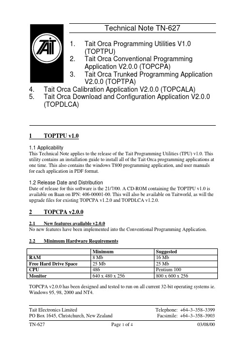
Technical Note TN-6271.Tait Orca Programming Utilities V1.0(TOPTPU)2. Tait Orca Conventional ProgrammingApplication V2.0.0 (TOPCPA)3. Tait Orca Trunked Programming ApplicationV2.0.0 (TOPTPA)4. Tait Orca Calibration Application V2.0.0 (TOPCALA)5. Tait Orca Download and Configuration Application V2.0.0(TOPDLCA)1 T OPTPU v1.01.1 ApplicabilityThis Technical Note applies to the release of the Tait Programming Utilities (TPU) v1.0. This utility contains an installation guide to install all of the Tait Orca programming applications at one time. This also contains the windows T800 programming application, and user manuals for each application in PDF format.1.2 Release Date and DistributionDate of release for this software is the 21/7/00. A CD-ROM containing the TOPTPU v1.0 is available on Baan on IPN: 406-00001-00. This will also be available on Taitworld, as will the upgrade files for existing TOPCPA v1.2.0 and TOPDLCA v1.2.0.2 T OPCPA v2.0.02.1 New features available v2.0.0No new features have been implemented into the Conventional Programming Application. 2.2 Minimum Hardware RequirementsMinimum SuggestedRAM8 Mb16 MbFree Hard Drive Space25 Mb25 MbCPU486Pentium 100Monitor640 x 480 x 256800 x 600 x 256TOPCPA v2.0.0 has been designed and tested to run on all current 32-bit operating systems ie. Windows 95, 98, 2000 and NT4.Tait Electronics LimitedPO Box 1645, Christchurch, New Zealand Telephone: +64–3–358–3399 Facsimile: +64–3–358–39032.3 ManualThe IPN for the Conventional Programming Application user manual is 439-51110-01. This is supplied with the software as "TOPCPA Manual.pdf".2.4 Known issues remaining with V1.2.0There are no known limitations or faults2.5 CompatibilityThis programming application is backward compatible with all conventional radio databases. Database versions supported are 2.00, 2.01, 2.03, 2.04, 2.05.3 T OPTPA v2.0.03.1New features available v2.0.0Feature Description Impact onCustomerMultiple Networks Up to 4 networks are supported with thissoftware.Major new feature3.2 Minimum Hardware RequirementsMinimum SuggestedRAM8 Mb16 MbFree Hard Drive Space25 Mb25 MbCPU486Pentium 100Monitor640 x 480 x 256800 x 600 x 256 TOPTPA v2.0.0 is designed and tested to run on all current 32-bit operating systems ie. Windows 95, 98, 2000 and NT4.3.3 ManualThe IPN for the Trunked Programming Application user manual is 439-51210-00. This is supplied with the software as "TOPTPA Manual.pdf".3.4 Known issues remaining with V2.0.0Issue Description Impact onCustomerPreset calls on networks 2-4If more than 9 presets are defined in networks2-4 then when programmed the Excel willdisplay preset 10 in position 1, preset 11 inposition 2 etc.Significant bug.Will be resolvedin the nextrelease.Nokia ANN dialling scheme When dialling scheme is set to "Nokia ANN"and the field MEP is edited before FEP thenerror "3617" occurs 4 times. To fix clear theerror each time and continue editing.MinorinconvenienceReading Archive files When reading an archive ops file an error willreset the "Trunked Channel Block Frequencies"to zero. To fix simply re-read the archive file.Minor inconvenience3.5 CompatibilityThis programming application is backward compatible with all trunked radio databases. Database versions supported are 1.05, 1.06, 1.07.4 T OPCALA v2.0.04.1 New features available v2.0.0No new features have been implemented into the Calibration Application.4.2 Minimum Hardware RequirementsMinimum SuggestedRAM8 Mb16 MbFree Hard Drive Space25 Mb25 MbCPU486Pentium 100Monitor640 x 480 x 256800 x 600 x 256 TOPCALA v2.0.0 has been designed and tested to run on all current 32-bit operating systems ie. Windows 95, 98, 2000 and NT4.4.3 ManualThe IPN for the Calibration Application user manual is 439-52010-01. This is supplied with the software as "TOPCALA Manual.pdf".4.4 Known issues remaining with V1.2.0There are no known limitations or faults4.5 CompatibilityThis product is compatible with all TOP radios built with embedded radio software fully approved prior to this release, on all appropriate TOP hardware platforms fully approved prior to this release.5 T OPDLCA v2.0.05.1 New features available v2.0.0No new features have been implemented into the Download and Configuration Application.5.2 Minimum Hardware RequirementsMinimum SuggestedRAM8 Mb16 MbFree Hard Drive Space25 Mb25 MbCPU486Pentium 100Monitor640 x 480 x 256800 x 600 x 256TOPDLCA v2.0.0 has been designed and tested to run on all current 32-bit operating systems ie. Windows 95, 98, 2000 and NT4.5.3 ManualThe IPN for the Download and Configuration Application user manual is 439-52010-01. This is supplied with the software as "TOPDLCA Manual.pdf".5.4 Known issues remaining with V1.2.0There are no known limitations or faults5.5 CompatibilityThis product is compatible with all Conventional and Trunked TOP radios. This product is compatible with both A1 and E1 microprocessors.Note to CSO’s This information is primarily of a technical nature. Use this information to fix reported problems. Distribute the programming software asrequired only.Issuing authority Terry McCartinMRD Customer Support - Tait Orca Portablesmailto:**********************.nzDDI: +64 3 358 6650。
浪潮英信服务器SA5112M4 NF5170M4用户手册说明书

出厂时的默认值,不要随意改变参数设置。 ④使用随机驱动程序或浪潮官网提供的驱动程序,如果使用非浪潮驱动程序,可能会引
起兼容性问题并影响产品的正常使用,对此浪潮将不承担任何责任或义务。浪潮将不 会对在使用我们的产品之前、期间或之后发生的任何损害负责,包括并不限于利益损 失、信息丢失、业务中断、人身伤害,或其他任何间接损失。
② Before disassembling the server’s components, please be sure to disconnect all the power cords connected to the server.
③ BIOS and BMC setup is significant to the configuration of your server. If there are no special requirements, you are suggested to use the default value and not alter the parameter settings arbitrarily.
④ Por favor, utilice los controladores que viene junto con el servidor o los que descarga por la página web oficial de Inspur. Si usa los controladores no de Inspur, puede causar problemas de compatibilidad y afectar el uso normal del producto. En este caso, Inspur no asumirá ninguna responsabilidad u obligación. Inspur no encarga las responsabilidades de ningún daño causado antes, durante o después del uso de nuestros productos, incluyendo, sin limitarse a pérdida de beneficios, pérdida de información, interrupción del negocio, lesiones personales o cualquier otra pérdida indirecta.
CMMI基础培训-V1.0
模型的表示法
阶段式(Staged) 连续式(Continuous)
一个过程模型,不仅给出规则和目标,还给出建议的具体实践和产出 物 只是一个模型,模型不是实施大纲,具体实践和产出物仅是建议性的, 不同的组织可以根据自身的实际情况确定或裁减
集成(Integrated)
以4个基本成熟度模型为基础 软件工程SW-CMM,系统工程SE-CMM,并行IPD-CMM,外购协作SSCMM
Jiangsu Microsoft Technology Center
30
过程域(PA)
一类相关实践活动的集合,建立过程能力最主要的元 素(模块)
目的,说明,相关的过程域 特定的目标(SG:Specific Goals)
特定的实践活动(SP:Specific Practices) 子实践活动(Subpractices) 典型工作产品(Typical Work Products)
CMM多种模型的存在给使用带来的方便,也带来了许多问题。 1997年,SEI停止了CMM2.0的研究,开始CMMI研究,其任务 是将已有的CMM模型结合成一个模型。 2000年,SEI推出CMMI 1.0,2003年,CMMI 1.1,2007年, CMMI 1.2。
Jiangsu Microsoft Technology Center
Jiangsu Microsoft Technology Center
12
成熟过程与不成熟过程的比较?
Video Intercom 第二锁配置指南说明书
How to Configure the Second Lock on Door StationPreparation2. Software: iVMS-4200 Version3.4.0.9How to Configure the Second Lock on Door Station1.Add Devices on iVMS-42001)Search for online devices and add the door station on iVMS-4200, enter usernameand password, and then confirm that the device is online.2.Add Indoor Station to Door Station1)Then go to Device Management → Add, set the Device Type as Indoor Station,fill in the necessary info of the device.Note: The password is the device’s password, if the device is inactive, set a new password in this page.The registration password is the password that must be configured for the activated device. When the door station adds an activated indoor station, the registration password of the indoor station must be known. The inactive indoor station can be directly assigned by door station. The Port is 8000.2)After we complete the device info, wait 5 to 10 minutes, you will see the page asshown below and the devices will be online3.Configure the Second lock on the Door Station1)Choose Configuration→Intercom→I/O Setting, Set the I/O Output No. Output2,enable it, and select Electric Lock as its value.2)When call the indoor station by door station, the user interface will be shown asbelow, you should notice there are two unlock options in the screen.。
工业边缘OPC UA应用程序V1.0操作手册10 2021 A5E50677101-AA说明书
Industrial Edge OPC UA Application V1.0Operating Manual10/2021A5E50677101-AALegal informationWarning notice systemThis manual contains notices you have to observe in order to ensure your personal safety, as well as to prevent damageto property. The notices referring to your personal safety are highlighted in the manual by a safety alert symbol, noticesreferring only to property damage have no safety alert symbol. These notices shown below are graded according tothe degree of danger.DANGERindicates that death or severe personal injuryWARNINGindicates that death or severe personal injury may result if proper precautions are not taken.CAUTIONindicates that minor personal injury can result if proper precautions are not taken.NOTICEindicates that property damage can result if proper precautions are not taken.If more than one degree of danger is present, the warning notice representing the highest degree of danger will beused. A notice warning of injury to persons with a safety alert symbol may also include a warning relating to propertydamage.Qualified PersonnelThe product/system described in this documentation may be operated only bypersonnel qualified for the specific task in accordance with the relevant documentation, in particular its warning notices and safety instructions.Qualified personnel are those who, based on their training and experience, are capable of identifying risks andavoiding potential hazards when working with these products/systems.Proper use of Siemens productsNote the following:WARNINGSiemens products may only be used for the applications described in the catalog and in the relevant technicaldocumentation. If products and components from other manufacturers are used, these must be recommended orapproved by Siemens. Proper transport, storage, installation, assembly, commissioning, operation and maintenanceare required to ensure that the products operate safely and without any problems. The permissible ambientconditions must be complied with. The information in the relevant documentation must be observed. TrademarksAll names identified by ® are registered trademarks of Siemens AG. The remaining trademarks in this publication maybe trademarks whose use by third parties for their own purposes could violate the rights of the owner. Disclaimer of LiabilityWe have reviewed the contents of this publication to ensure consistency with the hardware and software described.Since variance cannot be precluded entirely, we cannot guarantee full consistency. However, the information in thispublication is reviewed regularly and any necessary corrections are included in subsequent editions.Siemens AGDigital IndustriesPostfach 48 4890026 NÜRNBERGGERMANYA5E50677101-AAⓅ 10/2021 Subject to changeCopyright © Siemens AG 2021.All rights reservedTable of contents1General Data Protection Regulation (GDPR) (5)2Introduction to Industrial Edge OPC UA Application (7)3User Interface for OPC UA Configurator Home Page (13)4Working with OPC UA Configurator (19)4.1Add Data Source (19)4.2Add IE OPC UA Server User (22)4.3Start IE OPC UA Server (23)Industrial Edge OPC UA Application V1.0Operating Manual, 10/2021, A5E50677101-AA3Table of contentsIndustrial Edge OPC UA Application V1.0 4Operating Manual, 10/2021, A5E50677101-AAGeneral Data Protection Regulation (GDPR)1Siemens adheres to the principles of data protection, in particular the principles of dataminimization (Privacy by Design).For this product, Industrial Edge (IE) OPC UA application, this means:Personal dataThere is no personal data* collected but following data is stored to allow machine to machinecommunication:•Industrial Edge Databus credentials•OPC-UA server user credentials•User defined OPC-UA server certificates for encryption and signing•Tag data and metadata from SIMATIC S7 Connector•Timestamps•Choice of security and user authentication•Application usage dataIf the customer links the data mentioned above to other data (e.g. shift plans) or if the customersaves personal information on the same medium (e.g. hard disk) and thus creates a personalreference, the customer has to ensure that the guidelines regarding data protection areobserved.Note* This section refers to any personal data processed by the application other than the personaldata contained in log-files / tracking data (if any). "Personal data" are any information relating toan identified or identifiable natural person. Please note that IP-addresses, device identifiers suchas IMEI, UDID, IMSI, MAC-address, MSISDN, location data or machine data (if machine datatracks events triggered by user interaction with the machine) usually qualify as personal data.PurposesThe data mentioned above is required for the following purpose:•Access protection and security measuresStorage of the data is affected for a suitable purpose and is limited to what is strictly necessary,as the information is indispensable in order to identify the authorized operators.Industrial Edge OPC UA Application V1.0Operating Manual, 10/2021, A5E50677101-AA5General Data Protection Regulation (GDPR)Securing of dataThe above data will not be stored anonymously or pseudonymized, as the purpose(identification of the operating personnel) cannot be achieved otherwise. This data will be usedonly within the product and within the Edge eco-system and will not be automatically passed onto third parties or unauthorized persons. This data is secured by adequate technical measures,such as encryption.The customer must ensure the access protection as part of his process configuration while usingthe OPC UA client to connect to the server.Deletion policyThis product does not provide an automatic deletion for the databus and server user credentialsalready provided by the user. In case the user provides a different databus credentials, theprevious credentials will be overwritten. Since, there is no explicit delete option, the user couldprovide invalid databus credentials to overwrite the existing valid credentials. The OPC UA serveruser credentials can be overwritten and appended.Data configurationThe customer can configure the above data for the product using the App Configurator onIndustrial Edge Device. Once the configuration is completed, the data will be stored securely.Industrial Edge OPC UA Application V1.0 6Operating Manual, 10/2021, A5E50677101-AAIntroduction to Industrial Edge OPC UA Application2IE OPC-UA application on Industrial Edge (IE) devices provide open standard access to data thatis available to the customers. Industrial Edge (IE) OPC UA application allows to connect to thedata source and extract the data using Industrial Edge Databus (IE Databus). The data source canbe SIMATIC S7 Connector, PROFINET IO Connector, Modbus TCP Connector, or Ethernet/IPConnector. You can also customize data sources of your choice which supports common payloadformat.The IE OPC UA application installed on the IE devices and configured using IE OPC UAconfigurator. The application can be accessed using the end point as opc.tcp://Ip-Adress-of-Edge-Device:48010.NoteA client can connect to IE OPC UA server at end point opc.tcp://Ip-Adress-of-Edge-Device:48010.Any OPC UA client can be used to connect to IE OPC UA application as follows (UA expert is usedas an example client):Industrial Edge OPC UA Application V1.0Operating Manual, 10/2021, A5E50677101-AA7Introduction to Industrial Edge OPC UA ApplicationIndustrial Edge OPC UA Application V1.0 8Operating Manual, 10/2021, A5E50677101-AAIntroduction to Industrial Edge OPC UA ApplicationIndustrial Edge OPC UA Application V1.0Operating Manual, 10/2021, A5E50677101-AA9Introduction to Industrial Edge OPC UA ApplicationNoteIE OPC UA supports only DATA ACCESS (DA) as access method.•The non mandatory fields for server cnfiguration, server Capabilities - aggregate function and operation limits are set to default and should not be referred•Maximum number of data points - 6800 data points•Maximum number of data sources - 4•Maximum Number of client connections - 4•Number of client sessions per connection with values - 4•Maximum number of monitored Items - 1000•Minimal sample time- As per the IE data bus capabilityAbout OPC UA ConfiguratorThe IE OPC UA application uses IE OPC UA configurator to configure data source, securityconfiguration, and create users for OPC UA client to access the data.Industrial Edge OPC UA Application V1.0 10Operating Manual, 10/2021, A5E50677101-AAIntroduction to Industrial Edge OPC UA ApplicationRequirements for IE OPC UA Configurator•When SIMATIC S7 Connector is defined as a data source, there must be at least one connection in SIMATIC S7 Connector Configurator. All connections must be enabled with 'Bulk Publish'.• A user with username and password must be created in IE Databus. The required topics to fetch the tags must be configured in IE Databus.•The topics must be created for the user as shown in the below format:–ie/m/j/{msgStructureScheme}/{msgStructureSchemeMajorVersion}/ {providerAppInstanceId}/dp–ie/d/j/{msgStructureScheme}/{msgStructureSchemeMajorVersion}/ {providerAppInstanceId}/dp/r{dpConnectionNamePath}{dpCollectionNamePath}For example:–SIMATIC S7 Connector Configurator metadata and data subscriptions topics ie/m/j/simatic/v1/s7c1/dpie/d/j/simatic/v1/s7c1/dp/r/#Introduction to Industrial Edge OPC UA ApplicationUser Interface for OPC UA Configurator Home Page3Prerequisite The IE OPC UA Configurator app must be installed and running on the Industrial Edge Device.Home pageWhen you launch the IE OPC UA Configurator, the Configurator home page is displayed asfollows:①Server Status Tab ②Data Source Tab ③Data Points Tab ④Security Tab ⑤User Management Tab ⑥Message Logging Section⑦Deploy ButtonNoteThe message logging section displays the latest message at the end, and hence you need to scroll down towards the end of the message box.The IE OPC UA Configurator provides the following different user interface tabs:Server Status TabThis tab is displayed by default on the IE OPC UA Configurator home page. Once you deploy the configuration, this tab provides an overview on the current server status.Data Source TabThis tab allows you to add a data source for server. All existing configured data sources aredisplayed as follows:①Global Check Box②Add Data Source Icon③Connect Data Source Icon④Global Delete Icon⑤Delete Icon⑥Edit Icon⑦Check BoxThe following table lists the different UI elements in the "Data Source" tab page:UI Element DescriptionGlobal Check Box Using this check box, you can select all data source configurations.Add Data Source Icon Using this icon, you can add a data source.User Interface for OPC UA Configurator Home PageUI ElementDescription Connect Data Source IconUsing this icon, you can connect the data sources to Industrial Edge Runtime.Global Delete IconUsing this icon, you can delete all selected data source configurations.Delete IconUsing this icon, you can delete a data source configuration.Edit IconUsing this icon, you can edit the data source configuration.Check Box Using this check box, you can select a data source.When you make changes in the "Data Source" tab, you must either click "Deploy" or click toreflect the changes on the corresponding data points.Data Points TabThis tab allows you to view all data points, and select data points from the configured data sources. All data points from the configured data sources are displayed as follows:You must select atleast one data point to "Deploy".Security TabThis tab allows you to specify the security settings for the server. You can specify security policies and certificates as required as follows:User Interface for OPC UA Configurator Home PageNoteYou can use CA authorised certificate or generate self signed certificate also for the secured connections.IE OPC UA app supports only .der binary certificate and unprotected .pem private key for the secured communication.User Management TabThis tab allows you to add a user for server. All existing users are displayed as follows:User Interface for OPC UA Configurator Home Page①Global Check Box ②Add User Icon ③Global Delete Icon ④Delete Icon⑤Check BoxThe following table lists the different UI elements in the "User Management" tab page:UI ElementDescription Global Check Box Using this check box, you can select all users.Add User IconUsing this icon, you can add a user.Global Delete IconUsing this icon, you can delete all selected users.Delete IconUsing this icon, you can delete a user.Check Box Using this check box, you can select a user.NoteThe guest access should be disabled when users with passwords are used for a secure setup.Deploy ButtonDeploys the changes to Industrial Edge Runtime. It "Deploys" the configuration in each tab. Each tab displays its respective statuses, and in case of issues "Message" section in "Server" status tab can be referred for detailed information.User Interface for OPC UA Configurator Home PageUser Interface for OPC UA Configurator Home PageWorking with OPC UA Configurator4 4.1Add Data SourceYou can add a data source in IE OPC UA Configurator to fetch the data from the PLCs/datapublished through the IE Databus. This data is sent to OPC UA clients.Prerequisite•The IE OPC UA Configurator must be running.• A data source must be installed.ProcedureTo add a data source, follow these steps:unch the IE OPC UA Configurator.The IE OPC UA Configurator home page is displayed.2.Click "Data Source" tab.The page is displayed as follows:Working with OPC UA Configurator4.1 Add Data Source3.Click "Add".The "Add Data Source" dialog box is displayed as follows:plete the following fields:Field Name DefinitionData Source NameSpecifies the data source name. The data sources (connectors) that are installed in Industrial Edge Device, are displayed in the drop-down. Additionally, you can define another connector as required.Data Source typeDisplays the data source type.TopicWhen you specify the data source in "Data Source Name"field, the meta data topic is added in this field automatically. Addition‐ally, you can define a meta data topic as required. User nameDefines the username of IE Databus user.PasswordDefines the password of IE Databus user.NoteYou can add multiple data sources as required but the IE Databus username and password must be same for all the configured data sources.5.Click "OK".The data source is added and displayed as follows:Note•You can add more data sources using .•You can edit a data source using .•You can delete a data source using .•You can connect the added data sources to Industrial Edge Runtime using .•Duplicate entries of similar metadata topics are allowed.4.1 Add Data Source4.2Add IE OPC UA Server UserYou can create a user for OPC UA client to access OPC UA server. This provides a secure way of connection from OPC UA client for a session.PrerequisiteThe IE OPC UA Configurator must be running.ProcedureTo add a user, follow these steps:unch the IE OPC UA Configurator.The IE OPC UA Configurator home page is displayed.2.Click "User Management" tab.The page is displayed as follows:3.Click .The "Add User" dialog box is displayed as follows:4.2 Add IE OPC UA Server Userplete the following fields:Field Name DefinitionUser Name Definesthe username of the new user.Password Definesthe corresponding password of the user.Confirm PasswordConfirmsthe defined password.5.Click "OK".The user is added and displayed as follows:Note•You can add more users using .•You can delete a user using .•Any change in Security and User Management tab will restart the OPCUA Server on deploy.4.3Start IE OPC UA ServerThe IE OPC UA Configurator allows you to configure data source, security configuration, and create user for OPC UA client to access OPC UA server. When you deploy the connections and data points, the OPC UA server is started. The OPC UA clients can access this data through OPC UA server.PrerequisiteThe IE OPC UA Configurator must be running.ProcedureTo deploy the connections to the OPC UA server, follow these steps:4.3 Start IE OPC UA Server4.3 Start IE OPC UA ServerStep 1: Configure data source connection under "Data Source" tab.1.Add a data source as described in Add Data Source (Page 19) section.2.Connect the data source using .Step 2: Select tags under "Data Points" tab.1.Mark true against the check boxes of the connections and tags that you want to deploy asrequired. By default, all are marked true.Step 3: Select security policy under "Security" tab.1.Mark true against the check box of the security policy as required.The available options are as follows:•"None": It specifies no security. When you select the 'None' security policy, any OPC UA client can still connect using this setting, regardless of any security settings that follow.•"Sign-Basic256Sha256": It specifies secure communication with signed client and server certificates.•"Sign&Encrypt-Basic256Sha256": It specifies secure communication with signed client and server certificates with additional security where the data is encrypted from serverapplication and sent to the client.You must ensure that your selected security policy matches the algorithm that was used togenerate the certificates.Step 4: Upload certificate and key under "Security" tab.1.Upload the certificate and key using "Certificate" and "Key" field.This is an optional step. You may choose to upload the custom certificates or select "Generate selfsigned certificate" to generate self-signed certificates.NotePassword protected privatekey.pem file is not supported.Step 5: Create a user under "User Management" tab.1.Create a user as described in Add IE OPC UA User (Page 22) section.NoteAlternatively, you can mark true against "Enable guest access" check box to enable anonymouslogin. The default or recommended login procedure is by creating a user and using the usercredentials. You must use the anonymous login at your own risk.Step 6: Deploy Connections and tags.1.Click "Deploy".The connections and tags are deployed, and the OPC UA server is started.4.3 Start IE OPC UA ServerNote•When the OPC UA server disconnects from the IE Databus, it tries to connect to it for a certain duration. If the connection is not restored within this duration, a message is displayed on the UI that the maximum retry limit has reached. The next attempt to connect to the IE Databus is made only after the deployment of the Data Sources.•While using the IE OPC UA Configurator application, you must configure your client to validate the status code of the respective node. If the status code is set to ‘bad’, the value of the respective node should not be referenced.4.3 Start IE OPC UA Server。
AU3TECH A100M-3D 光驱切割机头用户操作手册说明书
A100M-3D Fiber Laser Cutting Head User’s ManualVersion V1.0WUHAN AU3TECH TRADING CO., LTD Tel*************Fax*************Daijiashan Technology Park,No.888 Hanhuang Road.****************ContentABSTRACT (2)K EY POINTS (2)R EADER O BJECTS (2)M ODIFICATION R ECORDS (2)INTRODUCTION (3)P RODUCT HIGHLIGHTS (3)S TRUCTURE (3)PRODUCT CONFIGURATION (5)T ECHNICAL PARAMETERS (5)C ONFIGURATION LIST (5)T HE APPEARANCE OF A100M-3D FIBER LASER CUTTING HEAD (6)INSTALLATION OF MECHANICAL PARTS (7)I NSTALLATION OF MAIN PARTS (7)I NSTALLATION OF W ATER COOLING (8)I NSTALLATION OF GAS CIRCUIT (8)F IBER SOCKET (9)T HE INSERTION AND LOCKING OF QBH FIBER (10)THE CENTERING AND ADJUSTMENT OF LASER BEAM (11)T HE CENTERING OF LASER BEAM (11)F OCUS ADJUSTMENT (12)CARE AND MAINTENANCE (13)O PTICAL LENS CLEANING; (13)D ISASSEMBLY AND INSTALLATION OF OPTICAL LENS: (14)R EPLACEMENT OF CAPACITIVE NOZZLE BODY (16)C OLLIMATE LENS UNIT AND FOCUS LENS UNIT OF A100M-3D FIBER LASER CUTTING HEAD. (18)AbstractKey pointsThis user’s manual contains basic installation, factory settings, operation, maintenance instructions and other descriptions of A100M-3D fiber laser cutting head. Since mechanical parts are too many, this manual will only introduce the main units.A100M-3D fiber laser cutting head, German brand A-cutter series, is designed for laser power within 1000w, which is a wonderful solution for medium and low power of laser 3D cutting application.Reader Objects●This document mainly is applicable to the following personnel:●Installation engineers●Maintenance engineers●OperatorsModification RecordsModification records accumulate the descriptions of the updating of the document. The latest version includes the updating contents of previous versions.Version V1.0 of Document (December, 2018)Initial release.IntroductionThis user’s manual contains basic installation, factory settings, operation, maintenance instructions and other descriptions of A100M-3D fiber laser cutting head. Since mechanical parts are too many, this manual will only introduce the main units.A100M-3D fiber laser cutting head was designed for 3D cutting within 1000w by German brand A-cutter in 2018. With optical lens group in D30 and multi interfaces design, A100M-3D fiber laser cutting head can be matched with different types of fiber laser sources. It’s much more stable during longtime working in high laser power with its optimized optical system and water cooling system.Product highlights●Precision optical elements●Perfect water-cooling system●High grade dustproof design●Precision machined parts●Wide range of focus adjustment in 10mm●With slim design of capacitive nozzle parts, it can be used for multi complicates 3D cuttingapplicationsStructureFrom figure 1, we can see that A100M-3D fiber laser cutting head contains five basic units: QBH interface, collimate unit, focus unit, protection unit, nozzle tips unit.Figure 1. The structure of A100M-3D fiber laser cutting head.●Fiber socket: Connect with fiber laser source.●Collimate unit: turn the incident laser beam into parallel beam,which can be adjust forcentering the laser beam.●Focus unit: turn the parallel beam into gathered beam with high energy, and adjust thefocus position in real time by regulating the focus unit.●Protective unit: avoid the focus lens being polluted by the dust from the surface of the metalsheet and by the metal dregs produced during cutting which can increase the service life of focus lens.●Nozzle tips unit: lead the gathered beam into the meal sheet and at the same time jet outhigh-speed gas flow to make sure the perfect cutting quality.Product configurationA100M-3D fiber laser cutting head was designed for 3D cutting within 1000W, which can be widely used in Robert hands or for tube/pipe cutting application. Its standard configuration is: A100M-3D-Z100-F125.Technical parametersConfiguration listPS: The list is our standard configuration.The appearance of A100M-3D fiber laser cutting head Figure 2. The appearance of A100M-3D fiber laser cutting head.Installation of mechanical partsInstallation of main partsThe size of installation hole of A100M-3D showed as figure 3. Please make sure the fiber laser cutting head is perpendicular to the metal sheet when installing and at the same time to make sure the cutting head has been locked stably on the cutting machine for getting a stable cutting quality.Figure 3. The size and position of installation hole of A100M-3D fiber laser cutting head.PS: The Z axis motor’s slide table for fixing the cutting head must be conducted with the cutting machine and must be in ground connection properly.Installation of Water coolingA100M-3D fiber laser cutting head has one water cooling circuit,you could self-configure the direction of water in and out. Kindly suggest you to use water cooling once the laser power is above 500w. The position and quantity of water cooling interface showed as below (Figure 4). The water cooling interface is a closed-loop design, but the cooling water can also be provided from the external and must be following the instructions showed as below:Figure 4. The interface of water cooling of A100M-3D fiber laser cutting headInstallation of gas circuitThe dregs like hydrocarbon and vapor contained in the cutting gas will damage the optical lens, and fluctuate the power of gathered laser beam which will result in the differences of the cutting sectionfrom the up to the bottom. Here are the suggested cutting gas and its purity (Figure 5). The higher the gas purity is, the better the cutting quality of section will be.The dregs can be filtered in the gas providing pipes while O2 and vapor can easily enter into the optical system by permeating nonmetal parts, which is the reason why dust and hydrocarbon appear inside the cutting head. So we kindly suggest you to use accessories in stainless steel and to use purifier that can filter particulate minimum in 0.01 μm. And suggest you to use diaphragm pressure gage in stainless steel, if you use diaphragm pressure gage in rubber, once the rubber aged, it can easily react with the air inhaled by the industrial pressure gage and generate hydrocarbon.A100M-3D fiber laser cutting head has 1 cutting gas circuit, the outside diameter of gas pipe is8mm. (Figure 5)Figure 5. The interface of cutting gas of A100M-3D fiber laser cutting head.PS: Please don’t change the gas connector randomly, especially don’t use PTFE tape to seal the gas connector or it may block the gas circuit thus affect the cutting quality and damage the cutting head.Fiber socketA100M-3D fiber laser cutting head can be matched with multi types of industrial laser source, it has collimate unit. The connected part between the end of optical fiber and cutting head was calledQBH connector. The standard fiber socket of A100M-3D fiber laser cutting head is QBH connector. (Figure 6)Figure 6. QBH connector of A100M-3D fiber laser cutting head.PS: All optical parts must be kept absolutely clean before using the cutting head. Please make sure the cutting head has been placed in horizon before installing the fiber in order to avoid the dust entering inside. Once all has been done, then start to fix the cutting head.The insertion and locking of QBH fiberFirstly, please let the red point of QBH fiber align with the marking red point of QBH socket; secondly, take out of the dust cover, and once the red point of QBH fiber aligned the marking red point of QBH socket, please insert the fiber into the bottom; thirdly, rotate the QBH hand wheel in clockwise until a “Tack” sound came out, then pull the hand wheel up; at last, rotate the QBH hand wheel in clockwise again until the end. (Figure 7)Figure 7. The insertion and locking of A100M-3D QBH fiber.The centering and adjusting of laser beam The centering of laser beamThe cutting quality mainly depends on whether the optical lens is in the center or not. If the optical lens is not in the center, the laser beam will reach to the inside parts of the cutting head thus the inside parts can be easily out of shape because of high temperature. Thus, whenever the cutting quality is getting worse, please try to adjust the position of optical lens or the nozzle tips and try again.Figure 8. The centering of laser beam of A100M-3D fiber laser cutting head.The centering of A100M-3D fiber laser cutting head can be done by adjusting the X-Y direction of collimate lens. Collimator Unit X/Y Adjustment showed as Figure 8. The adjustment can be done by using hexagonal screw driver until the laser beam is in the center of nozzle tips. Please make sure the laser beam is in the center of the nozzle tips before start cutting. Normally you could try to use this way to check if the laser beam is in the center of nozzle tips or not:(1) Take one piece of scotch tape and then horizontally stick on the bottom of nozzle tips;(2) Open the red light inside the laser source and then take out the scotch tape you stick on the nozzle tips to check if the red right is in the middle of the nozzle tip’s center hole. If not, please adjust the X-Y direction of collimate lens and repeat the first two steps until it does;(3) Open the laser source and adjust the power in the range of 80w to 100w, then manually enable the laser power in order to receive a spot on the tap;(4) Take out of the scotch tape to check if the cutting hole is exactly in the center of the nozzle tip’s hole;(5) Repeat all the steps above to find the best center position relative to the nozzle tip’s hole;This is the basic method to find the best center position of laser beam.Focus adjustmentFigure 9 is the focus adjustment unit of A100M-3D fiber laser cutting head. Rotate the focus adjustment unit in clockwise, the focus will go up in plus direction (Max: +5mm), opposite in anticlockwise (Max: -5mm).Figure9. Focus adjustment unit of A100M-3D fiber laser cutting head.The adjustment range of focus lens in Z direction is from “+5mm to -5mm”. When the dial is in “0” position, the focus is theoretically in the same level with the hole of nozzle tips. (Error may occur because the focus position of optical lens itself is not standard.)Care and maintenanceOptical lens cleaning;A100M-3D fiber laser cutting head has 2 types of protective windows: the one in the top is protective windows of collimate lens, the other one at the bottom is protective windows of focus lens. When there are dust or dregs on optical lens, the dust or dregs will absorb heat of the laser beam which can increase the temperature of the optical lens, then the optical lens can easily be out of shape and result in bad cutting quality. Thus, the optical lens clearing in regular is necessary. Kindly suggest you do the cleaning once a week. The components of each protective windows showed as Figure 10.Figure 10. The protective window’s components of A100M-3D fiber laser cutting head.■Tools for cleaning optical lens:Dust free gloves or fingerstall, cotton swab in polyester fiber, absolute ethyl alcohol, air blowing device in rubber (clean compressed air) etc.■ Optical lens cleaning method and Notes:(1) Please put on the fingerstall in the thumb and index finger of your left hand;(2) Spray some absolute ethyl alcohol on the cotton swab;(3) Hold the lens at its side edge by your thumb and index finger of your left hand(PS: Never hold the lens directly by your fingers without fingerstall, since the lens can easily be polluted )(4) Hold the lens up to the same horizon of your eyes and use the cotton fiber to wipe the lens gently from the bottom to the top or from the left to the right by your right hand (PS: The cleaning process can only be down in one certain direction, or the lens can easily be in repeated pollution.)(5) Use the air blowing device to sway the surface of the lens. Please clean the lens in both sides, and once the cleaning has been done, please double check if there are still any absolute ethyl alcohol/dust/dregs or other things are left on the lens.Disassembly and installation of optical lens:The whole process needs to be done in a clean place, and please take on the dust free gloves or fingerstall before disassembly.■ Disassembly and installation of protective windows of focus lens:Protective windows is vulnerable parts, please change with a new one once it has been damaged.(1) Loose the two screws showed in figure 11, and carefully take out of the lens with cover slide drawer;(2) Take out of the protective window upper seal ring by tools properly and take out of the lens using your fingers after putting on fingerstall;(3) Cleaning the lens, cover slide drawer and protective window upper seal ring, if the seal ring has been damaged, please change with a new one;(4) Put the cleaned lens back into the cover slide drawer; (No difference in pros and cons)(5) Put the protective window upper seal ring back to the cover slide drawer;(6) Put the protective windows unit back into the cutting head and then tighten the two screws.Figure 11. Protective windows of focus lens of A100M-3D fiber laser cutting head.■ Disassembly and installation of collimate lens:(1) Disassembly the cutting head and clean up all the dust on the surface of the head in a clean place;(2) Loosen all the screws of the collimate lens unit showed in figure 12 by hexagonal screw driver in 3mm, and kindly suggest you use masking tape to cover the part connecting with collimate lens for preventing dust coming inside;(3) Take out of the collimate lens with lens’ holder by the optics resemble tools and then take out of the screw ring and collimate lens by the same tool;(4) Clean or change the collimate lens;Figure 12. Collimate lens with lens’ holder of A100M-3D fiber laser cutting head.■ Disassembly and installation of focus lens:(1) Disassembly the cutting head and clean up all the dust on the surface of the head in a clean place;(2) Loosen all the screws of the focus lens unit showed in figure 13 by hexagonal screw driver in 4mm, and kindly suggest you use masking tape to cover the part connecting with focus lens for preventing dust coming inside;(3) Take out of t he focus lens with lens’ holder by optics resemble tools and then take out of the screw ring and focus lens by the same tool;(4) Clean or change the focus lens;Figure 13. Focus lens with lens’ holder of A100M-3D fiber laser cutting head. Replacement of capacitive nozzle bodyLaser cutting head sometimes would be hit during its working, and in that case, if unlucky, the capacitive nozzle body will need to be replaced. (Figure 14)■ Replacement of ceramic ring:(1) Screw off the nozzle tips;(2) Hold the ceramic ring straight and then screw off the lock ring;(3) Alignment the pin hole of the new ceramic ring with the 2 locating pin, and hold straight the ceramic ring, then screw on the lock ring;(4) Screw on nozzle tips and tighten it with proper strength.■ Replacement of nozzle tips:(1) Screw off the nozzle tips;(2) Screw on a new nozzle tips and tighten it with proper strength;(3) Head calibration must be done again after the replacement of nozzle tips or ceramic rings.Figure 14. Ceramic rings and nozzle tips of A100M-3D fiber laser cutting head.Collimate lens unit and focus lens unit of A100M-3D fiber laser cutting head.Figure 15. Collimate and focus lens’ assembly process of A100M-3D fiber laser cutting head.。