Fizeau Interferometery for THz-Waves' Frequency and Intensity Measurement
大尺度三维视觉测量中的离焦模糊图像恢复
De o u e l r i a e r so a i n i a g c l f c s d b u m g e t r to n l r e s a e 3D ii n m e s e e t v so a ur m n
表 学 报
Chn s o r a f ce t i n t me t i e eJ u n 1o ini c I sr S f u n
V0. .1 13l No 2
De c.2 0 01
21 0 0年 1 2月
大 尺 度 三 维 视 觉 测 量 中 的 离 焦 模 糊 图像 恢 复 术
,
meho sn e e . Unfru ae y,t e l n s al a x d fc lln t t d i e d d o t n tl h e su u l h sf e o a e g h,wh c a s sde c s d b u ma e wh l y i ih c u e f u e l e i g ie o o s r ig s e e n dfe e td sa c s b e vn c n s i i r n it n e ,wh c k st e c pt r d i g o eish g r qu n yf au e a d lmist f ih ma e h a u e ma el s t ih fe e c e t r n i t he
r s l t n o ma e mo a c I h s p p r a W in rfle s d ag rt m o e c s d b u ma e r so a in i e o u i fi g s i . n t i a e , e e tr ba e lo h f r d f u e l r i g e tr t s o i i o o
太赫兹时域光谱

太赫兹时域光谱
太赫兹时域光谱(Terahertz Time-Domain Spectroscopy,THz-TDS)是一种基于太赫兹波的光谱技术,用于研究物质的光学性质。
它利用太赫兹波的短脉冲和高频率特性,可以对物质的光谱信息进行高精度的测量。
THz-TDS 技术的基本原理是利用飞秒激光产生的太赫兹脉冲,通过测量太赫兹脉冲的时间延迟和幅度变化,得到物质的光谱信息。
THz-TDS 技术具有高灵敏度、高分辨率、高时间分辨率等优点,可以用于研究物质的结构、分子振动、电子态等信息。
THz-TDS 技术在材料科学、化学、生物医学等领域有着广泛的应用前景。
例如,它可以用于研究半导体材料的能带结构、分子的振动光谱、生物分子的构象等信息。
此外,THz-TDS 技术还可以用于检测物质的微量成分、检测食品中的有害物质等。
总之,THz-TDS 技术是一种非常有前途的光谱技术,具有高灵敏度、高分辨率、高时间分辨率等优点,在材料科学、化学、生物医学等领域有着广泛的应用前景。
用于激光频率参数测量的飞秒光学频率梳

用于激光频率参数测量的飞秒光学频率梳韩羿;曹士英;宋文霞;左娅妮;房芳【期刊名称】《仪器仪表学报》【年(卷),期】2024(45)2【摘要】近年来随着光纤制造技术和飞秒激光技术的成熟,以掺铒(Er)光纤光学频率梳为代表的频率梳技术,逐步突破了光学频率测量领域,在长度测量、精密光谱分析、超低相位噪声微波频率产生、精密时间频率传递、温度测量等领域发挥出越来越重要的作用,已成为许多高端科研领域的基础性工具。
但飞秒光学频率梳所解决的重要问题是对激光频率进行测量。
本文主要面向激光频率参数测量的需求,研制基于掺Er光纤飞秒激光器的光学频率梳,在实现光学频率梳稳定运转的前提下,通过非线性光学频率变换技术,实现光谱范围从掺Er光纤光学频率梳的中心波长向各个待测激光波长的转换,并完成与多个不同波长激光的拍频信号探测。
目前已验证的飞秒光梳可测频率范围为500~2000 nm;频率稳定度和准确度为10^(-16)量级;线宽为Hz量级。
该指标满足了激光频率特性参数测量的需求,为激光绝对频率、频率漂移、线宽等参数的测量提供了基础性的测量工具。
【总页数】16页(P31-46)【作者】韩羿;曹士英;宋文霞;左娅妮;房芳【作者单位】中国计量科学研究院时间频率计量科学研究所;国家市场监管重点实验室(时间频率与重力计量基准)【正文语种】中文【中图分类】TH741【相关文献】1.行走在路上——访“飞秒激光光学频率梳”项目负责人方占军2.“飞秒激光光学频率梳的研究”通过专家鉴定3.以I2和Rb为样品的激光频率标准与稳频飞秒光学频率梳的研制4.飞秒激光光学频率梳装置5.国家计量院飞秒激光光学频率梳获国家科技进步二等奖因版权原因,仅展示原文概要,查看原文内容请购买。
太赫兹(THz)技术资料讲解
太赫兹(THz)技术一、基本概念 (1)1. 太赫兹波 (1)2. 太赫兹波的特点 (1)二、国内外研究现状 (2)1. 美国 (3)2. 欧洲 (3)3. 亚洲 (3)三、太赫兹技术的应用 (4)1. 太赫兹雷达和成像 (4)2. 太赫兹通信 (5)3. 太赫兹安全检查 (6)4. 太赫兹无损检测 (7)5. 环境探测 (7)6. 生物医学 (8)7. 天文观测 (8)8. 材料特性的研究 (9)四、太赫兹技术的研究内容 (9)1. 太赫兹辐射源 (9)2. 太赫兹波段信号的探测 (10)3. 太赫兹功能器件 (10)五、我们能做些什么 (10)一、基本概念1.太赫兹波太赫兹(Terahertz)一词是弗莱明(Fleming)于1974年首次提出的,用来描述迈克尔逊干涉仪的光谱线频率范围。
太赫兹(THz, 1THz=1012Hz)频段是指频率从十分之几到十几太赫兹,介于毫米波与红外光之间相当宽范围的电磁辐射区域。
THz波又被称为T射线,在频域上处于宏观经典理论向微观量子理论的过渡区,在电子学向光子学的过渡区域。
长期以来由于缺乏有效的THz辐射产生和检测方法,对于该波段的了解有限,使得THz成为电磁波谱中最后一个未被全面研究的频率窗口,被称为电磁波谱中的“太赫兹空隙”(Terahertz Gap)。
2.太赫兹波的特点THz波具有很多独特的性质。
从频谱上看,THz 辐射在电磁波谱中介于微波与红外辐射之间;在电子学领域, THz辐射被称为毫米波或亚毫米波;在光学领域,它又被称为远红外射线;从能量上看, THz波段的能量介于电子和光子之间。
THz的特殊电磁波谱位置赋予它很多优越的特性,有非常重要的学术价值和应用价值,得到了全世界各国研究人员的极大关注。
THz 波的频率范围处于电子学与光子学的交叉区域。
在长波方向,它与毫米波有重叠,在短波方向,它与红外线有重叠。
在频域上, THz处于宏观经典理论向微观量子理论的过渡区。
FTIR光谱辐射计测量结果的非均匀性修正
FTIR光谱辐射计测量结果的非均匀性修正黄伟;吉洪湖;斯仁【摘要】由于探测器响应存在非均匀性,从而造成FTIR光谱辐射计测量结果也存在非均匀现象.通过对黑体辐射源进行测量,研究了不同视场时的方向响应分布,以及目标面积与视场面积之比对测量结果的影响.以目标理论辐射强度与仪器测量值之比作为修正系数,实现了对FTIR光谱辐射计测量结果的修正.研究结果表明:视场越大,方向响应的均匀性越差;目标与视场的面积比越小,测量值越偏离实际值;对FTIR 光谱辐射计的方向响应进行均匀性修正,可提高辐射强度测试精度.【期刊名称】《激光与红外》【年(卷),期】2015(045)004【总页数】6页(P400-405)【关键词】方向响应;均匀性;光谱辐射计;傅里叶变换;修正【作者】黄伟;吉洪湖;斯仁【作者单位】南京航空航天大学能源与动力学院,江苏省航空动力系统重点实验室,江苏南京210016;南京航空航天大学能源与动力学院,江苏省航空动力系统重点实验室,江苏南京210016;南京航空航天大学能源与动力学院,江苏省航空动力系统重点实验室,江苏南京210016【正文语种】中文【中图分类】TN2151 引言傅里叶变换红外(FTIR)光谱辐射计是一种建立在双光束干涉度量基础上,并应用傅里叶变换原理实现光谱测量的仪器[1],在环境[2-4]和目标辐射特征[5-7]等领域获得了广泛应用。
为了提高测量精度,研究人员对标定方法开展了广泛深入的研究,在标定源充满视场的情况下,研究了多点定标方法[8-10]以及复数光谱定标方法[1,11]。
Arthur等[12]对两种野外光谱仪的视场和方向响应(DRF)进行了研究,发现点源目标在视场中的方向不同时,光谱仪的响应差别非常明显。
引起光谱辐射计方向响应的一个主要因素是探测器的敏感面存在响应不均匀性,在光路设计上一个难以避免的问题,即使经过很好的设计[13],仍可能达到±5%~±8%。
拉曼与AFM联用 TERS
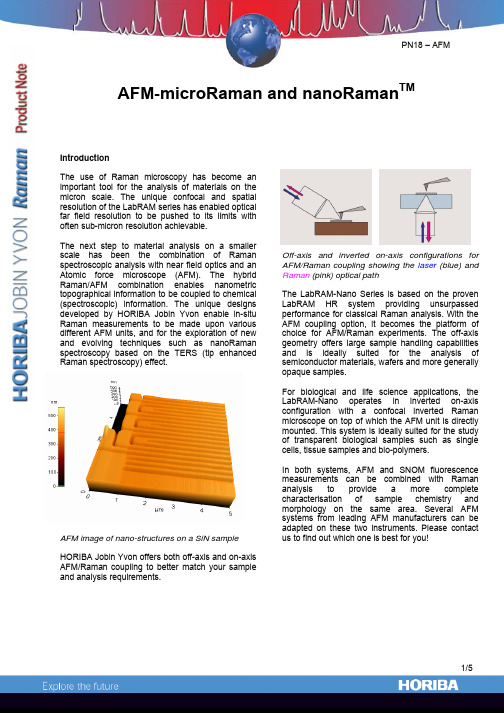
AFM-microRaman and nanoRaman TMIntroductionThe use of Raman microscopy has become animportant tool for the analysis of materials on themicron scale. The unique confocal and spatialresolution of the LabRAM series has enabled opticalfar field resolution to be pushed to its limits withoften sub-micron resolution achievable.The next step to material analysis on a smallerscale has been the combination of Ramanspectroscopic analysis with near field optics and anAtomic force microscope (AFM). The hybridRaman/AFM combination enables nanometrictopographical information to be coupled to chemical(spectroscopic) information. The unique designsdeveloped by HORIBA Jobin Yvon enable in-situRaman measurements to be made upon variousdifferent AFM units, and for the exploration of newand evolving techniques such as nanoRamanspectroscopy based on the TERS (tip enhancedRaman spectroscopy) effect.AFM image of nano-structures on a SiN sampleHORIBA Jobin Yvon offers both off-axis and on-axisAFM/Raman coupling to better match your sampleand analysis requirements.Off-axis and inverted on-axis configurations forAFM/Raman coupling showing the laser (blue) andRaman (pink) optical pathThe LabRAM-Nano Series is based on the provenLabRAM HR system providing unsurpassedperformance for classical Raman analysis. With theAFM coupling option, it becomes the platform ofchoice for AFM/Raman experiments. The off-axisgeometry offers large sample handling capabilitiesand is ideally suited for the analysis ofsemiconductor materials, wafers and more generallyopaque samples.For biological and life science applications, theLabRAM-Nano operates in inverted on-axisconfiguration with a confocal inverted Ramanmicroscope on top of which the AFM unit is directlymounted. This system is ideally suited for the studyof transparent biological samples such as singlecells, tissue samples and bio-polymers.In both systems, AFM and SNOM fluorescencemeasurements can be combined with Ramananalysis to provide a more completecharacterisation of sample chemistry andmorphology on the same area. Several AFMsystems from leading AFM manufacturers can beadapted on these two instruments. Please contactus to find out which one is best for you!AFM- microRaman dual analysisThe seamless integration of hardware and software of both systems onto the same platform enables fast and user-friendly operation of both systems at the same time. Furthermore, the AFM/Raman coupling does not compromise the individual capabilities of either system and the imaging modes of the AFM remain available (EFM, MFM, Tapping Mode, etc.)The operator has direct access to both the nanometric topography of a sample given by the AFM, and the chemical information from the micro-Raman measurement. An AFM image can berecorded as an initial survey map, in which regions of interest can be defined for further Raman analysis, using the same software.An example of such analysis is illustrated below by an AFM image of Carbon Nanotubes (CNTs) giving information on the CNTs’ length, diameters and aggregation state. A more detailed AFM image is then obtained in which Raman analysis can be performed.Carbon nanotubes AFM images with a gold-coated tip in contact mode. The diameter of the bundles of nanotubes is between 10 and 30 nm.NanoRaman for TERS experimentsSurface Enhance Raman Scattering (SERS) has long been used to enhance weak Raman signals by means of surface plasmon resonance using nanoparticle colloids or rough metallic substrates, allowing to detect chemical species at ppm levels.The TERS effect is based on the same principle, but uses a metal-coated AFM tip (instead of nanoparticles) as an antenna that enhances the Raman signal coming from the sample area which is in contact (near-field). Although not yet fully understood, the TERS effect has attracted a lot of interest, as it holds the promise of producing chemical images with nanometric resolution.The LabRAM-Nano offers an ideal platform,combining state-of-the-art AFMs with our Raman expertise to perform exploratory TERS experiments with confidence.Raman signal TERS enhancement on a Silicon sample with far field suppression thanks to adequate polarization configuration. Red : Far field + Near Field (tip in contact)– Blue : Far field only (tip withdrawn)Technical specificationsFlexure guided scanner is used to maintain zero background curvature below 2 nm out-of-planeFor non-TERS measurements, classical Raman measurements can be made on the same spot as AFM images by translating the sample with a high-accuracy positioning stage from the AFM setup to the Raman setup (and vice et versa). The AFM map can be used to define a region of interest for the Raman analysisusing a common software.LabRAM-Nano coupled with Veeco’s Dimension 3100 AFMThe on-axis coupling configuration enables both AFM-microRaman dual analysis and TERS measurementson transparent and biological samples. The AFM is directly coupled onto the inverted microscope and directlyinterfaced to the LabRAM HR microprobe. It can also be taken off the optical microscope to obtain AFMimages in a different location. Seamless software integration is realized to provide a common platform to bothsystems for both AFM and Raman analysis of the same area and TERS investigation.Bioscope II from VeecoLabRAM-Nano coupled with Park Systems(formerly PSIA) XE-120Off-axis coupling for AFM-microRaman and nanoRaman (TERS)For both dual AFM-microRaman dual analysis and TERS measurements, the off-axis coupling is ideally suited for opaque and large samples. For opaque samples, the inverted on-axis coupling is not possible as the sample will not transmit the laser beam. This can be solved by setting the microscope objective at some angle to avoid “shadowing” effects from the AFM cantilever. Here also, seamless software integration is realized to provide a common platform to both systems. The AFM can be controlled by the Raman software (LabSpec), and mapping areas can be defined on AFM images for further Raman analysis.France : HORIBA Jobin Yvon S.A.S., 231 rue de Lille, 59650 Villeneuve d’Ascq. Tel : +33 (0)3 20 59 18 00, Fax : +33 (0)3 20 59 18 08. Email : raman@jobinyvon.fr www.jobinyvon.frUSA : HORIBA Jobin Yvon Inc., 3880 Park Avenue, Edison, NJ 08820-3012. Tel : +1-732-494-8660, Fax : +1-732-549-2571. Email : raman@ Japan : HORIBA Ltd., JY Optical Sales Dept., 1-7-8 Higashi-kanda, Chiyoda-ku, Tokyo 101-0031. Tel: +81 (0)3 3861 8231, Fax: +81 (0)3 3861 8259. Email: raman@ LabRAM-Nano coupled with Park Systems (formerly PSIA) XE-100Combined polarized Raman and atomic force microscopy:In situ study of point defects and mechanical properties in individual ZnO nanobelts Marcel Lucas,1Zhong Lin Wang,2and Elisa Riedo1,a͒1School of Physics,Georgia Institute of Technology,Atlanta,Georgia30332-0430,USA2School of Materials Science and Engineering,Georgia Institute of Technology,Atlanta,Georgia30332-0245,USA͑Received8June2009;accepted23June2009;published online4August2009͒We present a method,polarized Raman͑PR͒spectroscopy combined with atomic force microscopy͑AFM͒,to characterize in situ and nondestructively the structure and the physical properties ofindividual nanostructures.PR-AFM applied to individual ZnO nanobelts reveals the interplaybetween growth direction,point defects,morphology,and mechanical properties of thesenanostructures.In particular,wefind that the presence of point defects can decrease the elasticmodulus of the nanobelts by one order of magnitude.More generally,PR-AFM can be extended todifferent types of nanostructures,which can be in as-fabricated devices.©2009American Instituteof Physics.͓DOI:10.1063/1.3177065͔Nanostructured materials,such as nanotubes,nanobelts ͑NBs͒,and thinfilms,have potential applications as elec-tronic components,catalysts,sensors,biomarkers,and en-ergy harvesters.1–5The growth direction of single-crystal nanostructures affects their mechanical,6–8optoelectronic,9 transport,4catalytic,5and tribological properties.10Recently, ZnO nanostructures have attracted a considerable interest for their unique piezoelectric,optoelectronic,andfield emission properties.1,2,11,12Numerous experimental and theoretical studies have been undertaken to understand the properties of ZnO nanowires and NBs,11,12but several questions remain open.For example,it is often assumed that oxygen vacancies are present in bulk ZnO,and that their presence reduces the mechanical performance of ZnO materials.13However,no direct observation has supported the idea that point defects affect the mechanical properties of individual nanostructures.Only a few combinations of experimental techniques en-able the investigation of the mechanical properties,morphol-ogy,crystallographic structure/orientation and presence of defects in the same individual nanostructure,and they are rarely implemented due to technical challenges.Transmis-sion electron microscopy͑TEM͒can determine the crystal-lographic structure and morphology of nanomaterials that are thin enough for electrons to transmit through,4,14–17but suf-fers from some limitations.For example,characterization of point defects is rather challenging.14–17Also,the in situ TEM characterization of the mechanical and electronic properties of nanostructures is very challenging or impossible.15–17 Alternatively,atomic force microscopy͑AFM͒is well suited for probing the morphology,mechanical,magnetic, and electronic properties of nanostructures from the micron scale down to the atomic scale.3,6,7,10In parallel, Raman spectroscopy is effective in the characterization of the structure,mechanical deformation,and thermal proper-ties of nanostructures,18,19as well as the identification of impurities.20Furthermore,polarized Raman͑PR͒spectros-copy was recently used to characterize the crystal structure and growth direction of individual single-crystal nanowires.21Here,an AFM is combined to a Raman microscope through an inverted optical microscope.The morphology and the mechanical properties of individual ZnO NBs are deter-mined by AFM,while polarized Raman spectroscopy is used to characterize in situ and nondestructively the growth direc-tion and randomly distributed defects in the same individual NBs.Wefind that the presence of point defects can decrease the elastic modulus of the NBs by almost one order of mag-nitude.The ZnO NBs were prepared by physical vapor deposi-tion͑PVD͒without catalysts14and deposited on a glass cover slip.For the PR studies,the cover slip was glued to the bottom of a Petri dish,in which a hole was drilled to allow the laser beam to go through it.The round Petri dish was then placed on a sample plate below the AFM scanner,where it can be rotated by an angle,or clamped͑see Fig.1͒.The morphology and mechanical properties of the ZnO NBs were characterized with an Agilent PicoPlus AFM.The AFM was placed on top of an Olympus IX71inverted optical micro-scope using a quickslide stage͑Agilent͒.A silicon AFM probe͑PointProbe NCHR from Nanoworld͒,with a normal cantilever spring constant of26N/m and a radius of about 60nm,was used to collect the AFM topography and modulated nanoindentation data.The elastic modulus of the NBs was measured using the modulated nanoindentation method22by applying normal displacement oscillations at the frequency of994.8Hz,at the amplitude of1.2Å,and by varying the normal load.PR spectra were recorded in the backscattering geometry using a laser spot small enough ͑diameter of1–2m͒to probe one single NB at a time.The incident polarization direction can be rotated continuouslywith a half-wave plate and the scattered light is analyzedalong one of two perpendicular directions by a polarizer atthe entrance of the spectrometer͑Fig.1͒.Series of PR spec-tra from the bulk ZnO crystals and the individual ZnO NBswere collected with varying sample orientation͑the NBs are parallel to the incident polarization at=0͒,in the co-͑parallel incident and scattered analyzed polarizations͒and cross-polarized͑perpendicular incident and scattered ana-lyzed polarizations͒configurations.For the ZnO NBs,addi-tional series of PR spectra were collected where the incidenta͒Electronic mail:elisa.riedo@.APPLIED PHYSICS LETTERS95,051904͑2009͒0003-6951/2009/95͑5͒/051904/3/$25.00©2009American Institute of Physics95,051904-1polarization is rotated and the ZnO NB axis remained paral-lel or perpendicular to the analyzed scattered polarization ͑see supplementary information 25͒.The exposure time for each Raman spectrum was 10s for the bulk crystals and 20min for NBs.After each rotation of the NBs,the laser spot is recentered on the same NB and at the same location along the NB.Prior to the PR characterization of ZnO NBs,PR data were collected on the c -plane and m -plane of bulk ZnO crystals ͓Fig.2͑a ͔͒.In ambient conditions,ZnO has a wurtzite structure ͑space group C 6v 4͒.Group theory predicts four Raman-active modes:one A 1,one E 1,and two E 2modes.11,20,23The polar A 1and E 1modes split into transverse ͑TO ͒and longitudinal optical branches.On the c -plane ͑0001͒-oriented sample,only the E 2modes,at 99͑not shown ͒and 438cm −1,are observed,and their intensity is independent of the sample orientation ͓Fig.2͑a ͔͒.On them -plane ͑101¯0͒-oriented sample,the E 2,E 1͑TO ͒,and A 1͑TO ͒modes are observed at 99,438,409,and 377cm −1,respectively ͓Fig.2͑a ͔͒,and their intensity depends on .Peaks at 203and 331cm −1in both crystals are assigned to multiple phonon scattering processes.The intensity,center,and width of the peaks at 438,409,and 377cm −1were obtained by fitting the experimental PR spectra with Lorent-zian lines ͑see supplementary information 25͒.The successful fits of the angular dependencies by using the group theory and crystal symmetry 23indicate that PR data can be used to characterize the growth direction of ZnO NBs.It is noted that the ZnO NBs studied here have dimensions over 300nm,so the determination of the growth direction is not ex-pected to be affected by any enhancement of the polarized Raman signal due to their high aspect ratio.24AFM images and PR data of three individual ZnO NBs are presented in Figs.2͑b ͒–2͑d ͒.These NBs,labeled NB1,NB2,and NB3,have different dimensions and properties assummarized in Table I .A comparison of the PR spectra in Figs.2͑a ͒–2͑d ͒reveals differences between bulk ZnO and individual NBs.First,the glass cover slip gives rise to a weak broadband centered around 350cm −1on the Raman spectra of the NBs ͓see bottom of Fig.2͑d ͔͒.Second,there are additional Raman bands around 224and 275cm −1for NB2and NB3.These bands are observed in doped or ion-implanted ZnO crystals.11,20Their appearance is explained by the disorder in the crystal lattice due to randomly distrib-uted point defects,such as oxygen vacancies or impurities.The defect peaks area increases in the order NB1ϽNB2ϽNB3.Since the laser spot diameter is larger than the width of all three NBs,but smaller than their length,L ,the NB volume probed by the laser beam is approximated by the product of the width,w ,with the thickness,t .ThevolumeFIG.1.͑Color online ͒Schematic of the experimental setup,showing the path of the laser beam.The ZnO NBs are deposited on a glass slide,which is placed inside a rotating Petridish.FIG.2.͑Color online ͒͑a ͒PR spectra from the c and m planes of a ZnO crystal,shown in blue and green,respectively.The wurtzite structure ͑Zn atoms are brown,O atoms red ͒is also shown,where a ء,b ء,and c ءare the reciprocal lattice vectors.͓͑b ͒–͑d ͔͒AFM images ͑3ϫ3m ͒of three NBs labeled NB1,NB2,and NB3and corresponding PR spectra.In ͑d ͒a PR spectrum of the glass substrate is shown at the bottom.All the PR spectra in ͑a ͒–͑d ͒are collected in the copolarized configuration for =0and 90°.The spectra are offset vertically for clarity.TABLE I.Summary of the PR-AFM results for NB1,NB2,and NB3.w ͑nm ͒t ͑nm ͒w /t L ͑m ͒͑°͒E ͑GPa ͒Defects NB11080875 1.24028Ϯ1562Ϯ5No NB21150710 1.64972Ϯ1538Ϯ5Yes NB315104553.35966Ϯ1517Ϯ5Yesprobed decreases in the order NB1͑wϫt=9.45ϫ103nm2͒ϾNB2͑8.17ϫ103nm2͒ϾNB3͑6.87ϫ103nm2͒.This indi-cates that the density of point defects is highest in NB3,and increases with the width to thickness ratio,w/t,in the order NB1ϽNB2ϽNB3.The PR intensity variations of the438cm−1peak as a function ofin the various polarization configurations were fitted by using group theory and crystal symmetry to deter-mine the anglebetween the NB long axis͑or growth di-rection͒and the c-axis͓͑0001͔axis͒of the constituting ZnO wurtzite structure21,23͑see supplementary information25͒.In-tensity variations of the377cm−1peak,when present,are used to confirm the obtained values of.The results are shown in Table I and indicate that growth directions other than the most commonly observed c-axis are possible,par-ticularly when point defects are present.Finally,the elastic properties of NB1,NB2,and NB3are characterized by AFM using the modulated nanoindentation method.6,7,22In a previous study,the elastic modulus of ZnO NBs was found to decrease with increasing w/t and this w/t dependence was attributed to the presence of planar defects in NBs with high w/t.6,7By using PR-AFM,we can study the role of randomly distributed defects,morphology,and growth direction on the elastic properties in the same indi-vidual ZnO NB.The measured elastic moduli,E,are62GPa for NB1,38GPa for NB2,and17GPa for NB3.These PR-AFM results confirm the w/t dependence of the elastic modulus in ZnO NBs,but more importantly they reveal that the elastic modulus of ZnO NBs can significantly decrease, down by almost one order of magnitude,with the presence of randomly distributed point defects.In summary,a new approach combining polarized Raman spectroscopy and AFM reveals the strong influence of point defects on the elastic properties of ZnO NBs and their morphology.Based on a scanning probe,PR-AFM pro-vides an in situ and nondestructive tool for the complete characterization of the crystal structure and the physical properties of individual nanostructures that can be in as-fabricated nanodevices.The authors acknowledge thefinancial support from the Department of Energy under Grant No.DE-FG02-06ER46293.1Y.Qin,X.Wang,and Z.L.Wang,Nature͑London͒451,809͑2008͒.2X.Wang,J.Song,J.Liu,and Z.L.Wang,Science316,102͑2007͒.3D.J.Müller and Y.F.Dufrêne,Nat.Nanotechnol.3,261͑2008͒.4H.Peng,C.Xie,D.T.Schoen,and Y.Cui,Nano Lett.8,1511͑2008͒. 5U.Diebold,Surf.Sci.Rep.48,53͑2003͒.6M.Lucas,W.J.Mai,R.Yang,Z.L.Wang,and E.Riedo,Nano Lett.7, 1314͑2007͒.7M.Lucas,W.J.Mai,R.Yang,Z.L.Wang,and E.Riedo,Philos.Mag.87, 2135͑2007͒.8M.D.Uchic,D.M.Dimiduk,J.N.Florando,and W.D.Nix,Science305, 986͑2004͒.9D.-S.Yang,o,and A.H.Zewail,Science321,1660͑2008͒.10M.Dienwiebel,G.S.Verhoeven,N.Pradeep,J.W.M.Frenken,J.A. Heimberg,and H.W.Zandbergen,Phys.Rev.Lett.92,126101͑2004͒. 11Ü.Özgür,Ya.I.Alivov,C.Liu,A.Teke,M.A.Reshchikov,S.Doğan,V. Avrutin,S.-J.Cho,and H.Morkoç,J.Appl.Phys.98,041301͑2005͒. 12Z.L.Wang,J.Phys.:Condens.Matter16,R829͑2004͒.13G.R.Li,T.Hu,G.L.Pan,T.Y.Yan,X.P.Gao,and H.Y.Zhu,J.Phys. Chem.C112,11859͑2008͒.14Z.W.Pan,Z.R.Dai,and Z.L.Wang,Science291,1947͑2001͒.15P.Poncharal,Z.L.Wang,D.Ugarte,and W.A.De Heer,Science283, 1513͑1999͒.16A.M.Minor,J.W.Morris,and E.A.Stach,Appl.Phys.Lett.79,1625͑2001͒.17B.Varghese,Y.Zhang,L.Dai,V.B.C.Tan,C.T.Lim,and C.-H.Sow, Nano Lett.8,3226͑2008͒.18M.Lucas and R.J.Young,Phys.Rev.B69,085405͑2004͒.19I.Calizo,A.A.Balandin,W.Bao,F.Miao,and u,Nano Lett.7, 2645͑2007͒.20H.Zhong,J.Wang,X.Chen,Z.Li,W.Xu,and W.Lu,J.Appl.Phys.99, 103905͑2006͒.21T.Livneh,J.Zhang,G.Cheng,and M.Moskovits,Phys.Rev.B74, 035320͑2006͒.22I.Palaci,S.Fedrigo,H.Brune,C.Klinke,M.Chen,and E.Riedo,Phys. Rev.Lett.94,175502͑2005͒.23C.A.Arguello,D.L.Rousseau,and S.P.S.Porto,Phys.Rev.181,1351͑1969͒.24H.M.Fan,X.F.Fan,Z.H.Ni,Z.X.Shen,Y.P.Feng,and B.S.Zou, J.Phys.Chem.C112,1865͑2008͒.25See EPAPS supplementary material at /10.1063/ 1.3177065for more information on the PR spectra.Growth direction and morphology of ZnO nanobelts revealed by combining in situ atomic forcemicroscopy and polarized Raman spectroscopyMarcel Lucas,1,*Zhong Lin Wang,2and Elisa Riedo1,†1School of Physics,Georgia Institute of Technology,Atlanta,Georgia30332-0430,USA 2School of Materials Science and Engineering,Georgia Institute of Technology,Atlanta,Georgia30332-0245,USA ͑Received26June2009;revised manuscript received28September2009;published14January2010͒Control over the morphology and structure of nanostructures is essential for their technological applications,since their physical properties depend significantly on their dimensions,crystallographic structure,and growthdirection.A combination of polarized Raman͑PR͒spectroscopy and atomic force microscopy͑AFM͒is usedto characterize the growth direction,the presence of point defects and the morphology of individual ZnOnanobelts.PR-AFM data reveal two growth modes during the synthesis of ZnO nanobelts by physical vapordeposition.In the thermodynamics-controlled growth mode,nanobelts grow along a direction close to͓0001͔,their morphology is growth-direction dependent,and they exhibit no point defects.In the kinetics-controlledgrowth mode,nanobelts grow along directions almost perpendicular to͓0001͔,and they exhibit point defects.DOI:10.1103/PhysRevB.81.045415PACS number͑s͒:61.46.Ϫw,61.72.Dd,78.30.Ly,81.10.ϪhI.INTRODUCTIONControl over the morphology and structure of nanostruc-tured materials is essential for the development of future de-vices,since their physical properties depend on their dimen-sions and crystallographic structure.1–15In particular,the growth direction of single-crystal nanostructures affects their piezoelectric,1,2transport,3catalytic,4mechanical,5–9 optoelectronic,10and tribological properties.11ZnO nano-structures with various morphologies͑wires,belts,helices, rings,tubes,…͒have been successfully synthesized in solu-tion and in the vapor phase,14–19but little is known about their growth mechanism,particularly in a process not involv-ing catalyst particles.17Understanding the growth mecha-nism and determining the decisive parameters directing the growth of nanostructures and tailoring their morphology is essential for the use of ZnO nanobelts as power generators or electromechanical systems.1,2,5,6From a theoretical stand-point,a shape-dependent thermodynamic model showed that the morphology of ZnO nanobelts grown in equilibrium con-ditions depends on their growth direction,but the role of defects was not considered.20Experimentally,it was shown that the growth direction of ZnO nanostructures can be di-rected by the synthesis conditions,such as the oxygen con-tent in the furnace.19A previous study combining scanning electron microscopy and x-ray diffraction suggested a growth-direction-dependent morphology.20An atomic force microscopy͑AFM͒combined with transmission electron mi-croscopy also suggested that the morphology of ZnO nano-belts is correlated with their growth direction and highlighted the potentially important role of planar defects.5 Growth modes out of thermodynamic equilibrium and the role of point defects5,17are particularly challenging to inves-tigate experimentally,21due to the lack of appropriate experi-mental techniques.Electron microscopy can determine the crystallographic structure and morphology of conductive nanomaterials,3,17,22–24but is not suitable for the character-ization of point defects,especially when their distribution is disordered.17,22–24Raman spectroscopy has been used for the characterization of the structure of carbon nanotubes,25,26the identification of impurities,27and the determination of the crystal structure28and growth direction of individual single-crystal nanowires.29Recently,polarized Raman͑PR͒spec-troscopy has been coupled to AFM to study in situ the inter-play between point defects and mechanical properties of ZnO nanobelts.30Here,PR-AFM is used to study the growth mechanism and the relationship between growth direction,point defects, and morphology of individual ZnO nanobelts.The morphol-ogy of an individual ZnO nanobelt is determined by AFM, while the growth direction and randomly distributed defects in the same individual nanobelt are characterized by polar-ized Raman spectroscopy.II.EXPERIMENTALThe ZnO nanobelts were prepared by physical vapor deposition͑PVD͒without catalysts following the method de-scribed in Ref.17.The ZnO nanobelts were deposited on a glass cover slip,which was glued to a Petri dish.The rotat-able Petri dish was then placed on a sample plate under an Agilent PicoPlus AFM equipped with a scanner of100ϫ100m2range.Topography images of the ZnO nanobelts were collected in the contact mode with CONTR probes͑NanoWorld AG,Neuchâtel,Switzerland͒of normal spring constant0.21N/m at a set point of2nN.The AFM was placed on top of an Olympus IX71inverted optical micro-scope that is coupled to a Horiba Jobin-Yvon LabRam HR800.PR spectra were recorded in the backscattering ge-ometry using a40ϫ͑0.6NA͒objective focusing a laser beam of wavelength785nm on the sample to a power den-sity of about105W/cm2and a spot size of about2m. The incident polarization direction can be rotated continu-ously with a half-wave plate.The scattered light was ana-lyzed along one of two perpendicular directions by a polar-izer at the entrance of the spectrometer.The intensity,center, and width of the Raman bands were obtained byfitting the spectra with Lorentzian lines.The polarization dependence of the quantum efficiency of the Raman spectrometer was tested by measuring the intensity variations of the377,409,PHYSICAL REVIEW B81,045415͑2010͒1098-0121/2010/81͑4͒/045415͑5͒©2010The American Physical Society045415-1and 438cm −1bands from two bulk ZnO crystals ͑c -plane and m -plane ZnO crystals,MTI Corporation ͒.The PR data from bulk crystals were successfully fitted using group theory and crystal symmetry 28without further calibration of the spectrometer or data correction.III.RESULTS AND DISCUSSIONAFM images and PR data of two individual ZnO nano-belts are presented in Fig.1.These nanobelts have different cross-sections,1320ϫ1080nm 2͑nanobelt labeled NB A͒FIG.1.͑Color online ͒PR-AFM results on individual ZnO nanobelts.͑a ͒AFM topography image,͑b ͒typical PR spectra for different sample orientations and polarization configurations,and ͑c ͒–͑f ͒polar plots of the angular dependence of the Raman intensities for the nanobelt NB A.͑g ͒AFM topography image,͑h ͒typical PR spectra,and ͑i ͒–͑l ͒polar plots of the angular dependence of the Raman intensities for the nanobelt NB B.The Raman spectra in ͑h ͒exhibit peaks centered at 224and 275cm −1͑triangles ͒that are characteristic of defects in the nanobelt NB B.The Raman spectra are offset vertically for clarity.In ͑c ͒,͑d ͒,͑i ͒,and ͑j ͒,the nanobelt axis is rotated in a fixed polarization configuration ͑solid squares:copolarized;open squares:cross polarized ͒and is parallel to the incident polarization for =0°.In ͑e ͒,͑f ͒,͑k ͒,and ͑l ͒,the incident polarization is rotated,while the analyzed polarization and the nanobelt axis are fixed.In ͑e ͒,͑f ͒,͑k ͒,and ͑l ͒,at the angle 0°,the nanobelt is perpendicular to the incident polarization and the incident and analyzed polarizations are parallel ͑solid squares ͒or perpendicular ͑open squares ͒.Typical Raman spectra of the glass cover slip in the copolarized and cross-polarized configurations are shown as a reference in ͑b ͒and ͑h ͒,respectively.LUCAS,WANG,AND RIEDO PHYSICAL REVIEW B 81,045415͑2010͒045415-2。
2-Wave-optics
Phase difference ϕ is given as ϕ = ω∆t = 2π f ∆t = 2π (n v/λ) ∆t = 2π nd/λ or ϕ / 2π = nd/λ = Optical Path difference/wavelength of light I= E2 = (4A2cos2 φ/2) cos2 (ωt + φ/2)
cannot be explained by geometrical optics Geometrical optics would say that light rays traveling in straight lines should cast a sharp image of the slit on the screen But what we see is a pattern similar to an interference pattern made up of dark and bright lines.
2 Recorded intensity at point I = E 2 = 4 A2 cos2
I = E = [4 A cos
2 2
2
ϕ
Interference
] cos (ωt +
2
ϕ
2
)
ϕ
2
= 2 A2 (1 + cos ϕ )
φ= 2π nd/λ=2π (OPD)/λ
Constructive Interference I = Imax – bright fringe when ϕ =N 2π Or when OPD = Nλ where N =0,1,2,…. Destructive Interference I = Imin – dark fringe when ϕ = (N+0.5)2π Or when OPD = (N+0.5) λ OPD – Optical Path Difference
基于DSHI的窄线宽光纤激光器线宽测量
基于DSHI的窄线宽光纤激光器线宽测量肖华菊;王翔;马云;张洁【摘要】窄线宽光纤激光器的线宽作为相干光学系统的重要参数需要进行准确的测定,延时自外差法(DSHI)是测量窄线宽比较理想的方法.本文讨论了DSHI测量线宽的基本原理,根据DSHI的功率谱表达式,利用MATLAB程序对不同光纤延迟线长度条件下的DSHI功率谱进行了仿真,并分析和讨论了光纤延迟线长度对线宽测量结果的影响.建立了1550 nm波长的DSHI线宽测量系统,对IPG公司的光纤激光器线宽进行了测量.该系统用示波器代替频谱仪,并采用FFT软件算法对示波器获取的光电流信号进行分析,测得该激光器的线宽约为16 kHZ,在理想的精度范围内.【期刊名称】《光电工程》【年(卷),期】2010(037)008【总页数】5页(P57-61)【关键词】线宽测量;光纤激光器;DSHI;光纤延时【作者】肖华菊;王翔;马云;张洁【作者单位】中国工程物理研究院,流体物理研究所,冲击波物理与爆轰物理实验室,四川,绵阳,621900;西南交通大学,机械工程学院,成都,610031;中国工程物理研究院,流体物理研究所,冲击波物理与爆轰物理实验室,四川,绵阳,621900;中国工程物理研究院,流体物理研究所,冲击波物理与爆轰物理实验室,四川,绵阳,621900;西南交通大学,机械工程学院,成都,610031【正文语种】中文【中图分类】TN247%TN2530 引言窄线宽光纤激光器在光学测量和光通信领域有着十分广泛的应用,在许多系统中,如全光纤干涉仪、光纤载波传输系统、基于FMCW(Frequency-modulated Continuous Wave)技术的光纤传感系统等,激光器的线宽特性对于系统精度有着十分重要的作用[1]。
在FMCW技术系统中,激光器的线宽或相干长度决定了测量的距离和灵敏度。
因此,对这类激光器的线宽进行测量是一项非常重要并且有意义的工作。
延时自外差法简称DSHI(Delayed Self-heterodyne Interferometer),是测量窄线宽比较理想的方法。
非制冷红外焦平面非均匀性测试技术研究
第36卷,增刊红外与激光工程2007年6月V 01.36Suppl 锄【entI n 劬r ed 卸d L 弱e r E ngi I 雠ri ngJun .2007非制冷红外焦平面非均匀性测试技术研究钱芸生,张俊举,孙恋君,邢素霞,常本康(南京理工大学电子工程与光电技术学院,江苏南京210094)摘要;非制冷焦平面的非均匀性和噪声是限制非制冷红外热成像系统性能的主要因素。
研制了非制冷红外焦平面的非均匀性测试系统,系统由黑体、红外光学系统、焦平面驱动电路、热电温控电路、信号处理系统、计算机和测试软件等构成,利用该系统可以将微测辐射热计非制冷红外焦平面各像元的输出信号数字化后传输给计算机,实现对焦平面的非均匀性测试和盲元统计,并给出了实验结果。
关键词:非制冷红外焦平面;微测辐射热计;非均匀性;测试中图分类号:T N 216文献标识码:A 文章编号:1007—2276(2007)增(器件)一0129—04N on .uni f I i v s ur of uncool ed i nf .r ared f bcal pl a ne—O n —U nl l or m l t V m ea SU r e m ent ol U nC 00l ed l nI r ar en 10C a I pI ane a r r a yQ L 气N Y un —s heng ,Z H 【A N G Jun-j u ,SU N Li aI l -j un ,X I N G Su —xi a ,C H 【A N G B e n —ka Il g(School ofEl e ct f o ni cEngin ∞r 吨&Phot ∞l ∞Ⅱi c 陬hnol ogy 。
N 删她uni V ∞畸of sci ∞cc &Tcchnol ogy ,N 删咄210094,chi l m )A bst r act :N on —uI l i f o 加[1i 够and noi s e of unco ol edi Il f 删fbcalpl anear r ays(U 阳A)r est r i ctt 11e perf om anceofunco ol ed i nf rar e d i m ag i ng sys t em 。
太赫兹时域光谱
量子相干和控制
量子数 n=20 到 n=60 的里德伯原子正好覆盖了太赫兹光谱频段,所以它们是研究许多量
子力学问题的最佳模型。
已经有许多实验证明了太赫兹辐射在这项研究中的可用性,如在里德伯原子中产生和探测 任意的电子波包。对于这项研究工作,半周期的太赫兹脉冲是十分重要的,因为它具有宽广的 光谱范围,所以可以同时和上百个里德伯能级发生相互作用。实际上半周期脉冲已经被用来分
极端条件下的物质探测
采用高强度飞秒激光激发的等离子体存有许多潜在的应用价值。比如它能产生软X射线脉 冲、相干谐波,以及构成基于等离子体的加速器等。从基础研究的角度来看,人们就能够探测 物质和极强电磁场之间的相互作用,这种电磁场一般比原子中束缚电子的电场要大几个数量级。 最近的研究工作表明这种等离子体可以成为太赫兹强场的辐射源。
辨率、亚周期的时间分辨率来对复杂的波阵面进行相干测量。另外,利用太赫兹还可以对场统 计学和场相关性进行直接研究。
左手材料
“左手材料”是指一种介电常数和磁导率同时为负值的材料。电磁波在其传播时,波矢k、 电场E和磁场H之间的关系符合左手定律。目前研究人员对于这类材料的研究还集中在微波波段。 但人们会很自然把这一想法扩展到其他频段,而太赫兹波段理所应当的属于最佳的候选波段。
电磁场的能力也不断增强。
• 随着太赫兹脉冲强度和带宽的不断增加,研究人员相信该领域必将出现很多新的机遇。例如, 在高于 1MV/cm 的场强中,太赫兹脉冲不仅能够进行探测,而且还能激发气相和溶液中的离 子态。从而可以对一些基础性问题进行研究,如溶液中太赫兹活性分子(THz-active molecules)的溶剂环境。 • 太赫兹技术还为识别周围环境中复杂的有机分子提供了新的方法。 • 利用整形过后的强太赫兹脉冲可以来研究经典量子通信、量子算法、量子局域化以及量子混
- 1、下载文档前请自行甄别文档内容的完整性,平台不提供额外的编辑、内容补充、找答案等附加服务。
- 2、"仅部分预览"的文档,不可在线预览部分如存在完整性等问题,可反馈申请退款(可完整预览的文档不适用该条件!)。
- 3、如文档侵犯您的权益,请联系客服反馈,我们会尽快为您处理(人工客服工作时间:9:00-18:30)。
Journal ofBeijingInstituteofTechnology,2007,Vo1.16,No.3 Fizeau Interferometery for THz—Waves’Frequency and Intensity Measurement
SIDDIQUE Muhammad(西迪科), YANG Su—hui(杨苏辉), LI Zhuo(李卓),LI Ping(李萍) (school of Information Science and Technology,Beijing Institute of Technology,Beijing 100081,China)
Abstract:A terahertz-wave generator based on optical parametric oscillator principle,detection based on com— bination of Fizeau wedged intederometer and an electro-optical crystal ZnTe has been studied.The analytical solution based on the basic principle of operation of solid wedge Fizeau interferometer has been realized.The mathematical calculations for TI-Iz frequency and intensity measurement dependent on wedge angle and fringe spacing have been considered.The efficiency of THz wave detection depends upon optimized wedge angle has been also realized.The feasibility of detection of TI-Iz waves’frequency and intensity by solid Fizeau inteder— ometer(THz-waves’range of 1—3 TI-Iz)has been studied.By optimization of other parameters like thickness of Fizeau film,refractive index,material of Fizeau film,we can proceed towards the design of Fizeau inteder— ometer for required research plans as it is a simple and inexpensive intederometer.
Key words:terahertz;Fizeau intederometer;electro-optical crystal CLC number:O 437 Document code:A Article ID:1004—0579(2007)03—0326—04
With the increased use of tunable Terahertz has come the need for instruments to measure their output wavelengths rapidly and accurately.A number of wavemeters,based on fl variety of different operating principles have been described in Refs.[1—3].The idea of fl small practical wavelength meter for the laser spectroscopy laboratory has grown closer to reality during the past few years with the introduction of several high resolution rea1..time wavemeter de.. signs[¨.Amongst the most promising of these is the Fizeau wedge wavemeter,whose passive optical con— figuration forms fl stable broadband instrument use— able with pulsed and CW laser sources.In 1981,the University of Maryland and the National Bureau of Standards have collaborated in the development and testing of fl Fizeau wavemeter optimized for use with pulsed laser sources,and this paper will describe our theoretical work on the design of fl Fizeau wavelength wave meter in the range of THz regime of 1—3 THz. The increasing availability of inexpensive micro— processors has made the option of digitally analyzing interference fringes in real time ever more tempting. In interferometry,the period and/or phase of fl fringe pattern may be the parameters of interest,since they allow direct comparison of optical path lengths with the wavelengths of the illuminating light.For exam— pie,in our application we measure the wavelengths of THz wave by analyzing the interference beams by ZnTe crystal,whose property is to modulate by the reference beam in to near infrared or visible laser range.THz wave produces in reflection from fl Fizeau interferometer whose wedge was accurately known. The Fizeau wavemeter is fl high resolution real—time stable broadband instrument with fl simple passive op— tical configuration[ 一 ]usable with pulsed as well as
with cw laser and THz sources.
1 Basic Principle of Operation The operation of fl interferometer requires vacuum—spaced Fizeau wedge that the Fizeau wedge be
Reeeived 2006—07—07 Biographies SIDDIQUE Muhammad(1969一),doctoral student,mrsiddik@yahoo.com;LI Zhuo(1958~),professor,lizhuo@bit.edu.cn
326
维普资讯 http://www.cqvip.com sJDDJQuE Muhnmm (西迪科) n1./Fizea“Interferometery for THz-Waves’Freq“ 彻d J £朗s M s“ m阴£ enclosed in fl container that maintains a vacuum.a re—
quirement that makes construction of the instrument
difficult.Placing the Fizeau wedge in fl vacuum con—
tainer and sending light into and out of the wedge via
fl window cause errors to be introduced by the disper— sion effects that occur in the window.Various tech.
niques have been suggested[7】for easing the vaCUUm
requirements and improving the accuracy of the Fizeau wavemeter.These include filling the inter[er— ometer with a calibrated amount of gas[7]bringing the detector array into close proximity to the inter[erome— ter,or using multiple inter[erometers.Such systems may eliminate the vacuum requirement but still re— sults in instruments being difficult and expensive to
corlS【rUC【. Operation of fl wavemeter with an SFI is similar to the operation of fl vacuum—spaced Fizeau wedge in— strument as described by Snyder[ (see Fig.1).In—