电压暂升暂降指标计算
电压降计算方法

电缆电压降对于动力装置,例如发电机、变压器等配置的电力电缆,当传输距离较远时,例如900m,就应考虑电缆电压的“压降”问题,否则电缆采购、安装以后,方才发觉因未考虑压降,导致设备无法正常启动,而因此造成工程损失。
一.电力线路为何会产生“电压降”?电力线路的电压降是因为导体存在电阻。
正因为此,所以不管导体采用哪种材料(铜,铝)都会造成线路一定的电压损耗,而这种损耗(压降)不大于本身电压的10%时一般是不会对线路的电力驱动产生后果的。
二.在哪些场合需要考虑电压降?一般来说,线路长度不很长的场合,由于电压降非常有限,往往可以忽略“压降”的问题,例如线路只有几十米。
但是,在一些较长的电力线路上如果忽略了电缆压降,电缆敷设后在启动设备可能会因电压太低,根本启动不了设备;或设备虽能启动,但处于低电压运行状态,时间长了损坏设备。
较长电力线路需要考虑压降的问题。
所谓“长线路”一般是指电缆线路大于500米。
对电压精度要求较高的场合也要考虑压降。
三.如何计算电力线路的压降?一般来说,计算线路的压降并不复杂,可按以下步骤:1.计算线路电流I公式:I= P/1.732×U×cosθ其中: P—功率,用“千瓦” U—电压,单位kV cosθ—功率因素,用0.8~0.852 .计算线路电阻R公式:R=ρ×L/S其中:ρ—导体电阻率,铜芯电缆用0.01740代入,铝导体用0.0283代入L—线路长度,用“米”代入S—电缆的标称截面3.计算线路压降公式:ΔU=I×R举例说明:某电力线路长度为600m,电机功率90kW,工作电压380v,电缆是70mm2铜芯电缆,试求电压降。
解:先求线路电流II=P/1.732×U×cosθ=90÷(1.732×0.380×0.85)=161(A)再求线路电阻RR=ρ×L/S=0.01740×600÷70=0.149(Ω)现在可以求线路压降了:ΔU=I×R =161×0.149=23.99(V)由于ΔU=23.99V,已经超出电压380V的5%(23.99÷380=6.3%),因此无法满足电压的要求。
电能质量补偿方案
电能质量补偿方案1. 引言随着现代电力系统的发展,电能质量问题逐渐凸显。
电能质量问题包括电压波动、频率偏差、谐波、电压暂降、电压暂升等。
这些问题会影响到电力设备的正常运行,甚至造成设备损坏。
为了改善电能质量,电能质量补偿方案得到了广泛关注。
本文将介绍电能质量补偿方案的基本原理,并探讨常见的补偿方法。
2. 电能质量问题分析在了解电能质量补偿方案之前,有必要先对电能质量问题进行分析。
以下是常见的电能质量问题及其影响:电压波动是指正常电压值在一时间段内发生剧烈变化的现象。
电压波动会影响电力设备的正常工作,尤其是对电机等感性负载产生不良影响。
2.2 频率偏差频率偏差是指电力系统的供电频率与标准频率(通常为50Hz或60Hz)之间的差异。
频率偏差会使电力设备的工作速度产生变化,从而影响设备的性能。
2.3 谐波谐波是指电力系统中存在的频率为基频整数倍的频率成分。
谐波会导致电流和电压的畸变,从而影响电力设备的正常运行。
电压暂降是指电力系统中出现短暂的低电压现象。
电压暂降会导致电力设备失去正常工作条件,造成停电或设备故障。
2.5 电压暂升电压暂升是指电力系统中出现短暂的高电压现象。
电压暂升会使电力设备受到过高的电压冲击,从而导致设备损坏。
3. 电能质量补偿方案为了解决电能质量问题,可以采取多种电能质量补偿方案。
3.1 电压稳定器电压稳定器可以对供电电压进行调节,以保持其在一定范围内的稳定。
电压稳定器通过调整输出电压来消除电压波动和电压暂降的影响。
3.2 频率调整装置频率调整装置可以通过对电力系统进行频率调整,来消除频率偏差的影响。
常见的频率调整装置包括转子型发电机和电子频率变换器。
3.3 谐波滤波器谐波滤波器可以对电力系统中的谐波进行滤除。
谐波滤波器采用并联或串联的方式与电力系统相连,通过选择合适的滤波参数来消除谐波的影响。
3.4 电压调节器电压调节器可以通过调节电力系统中的电流,来消除电压暂降和电压暂升的影响。
SEMI F047-000-0706-en电压暂升暂降标准

S E M I®SEMI F47-0706SPECIFICATION FOR SEMICONDUCTOR PROCESSING EQUIPMENT VOLTAGE SAG IMMUNITYThis standard was technically approved by the global Facilities Committee. This edition was approved for publication by the global Audits and Reviews Subcommittee on May 16, 2006. It was available at in June 2006 and on CD-ROM in July 2006. Originally published September 1999; Previously published February 2000. NOTICE: This document was completely rewritten in 2006. This document replaces SEMI F47-0200 and SEMI F42-0600.1 Purpose1.1 Semiconductor factories require high levels of power quality due to the sensitivity of equipment and process controls. Semiconductor processing equipment is especially vulnerable to voltage sags. This specification defines the voltage sag immunity required for semiconductor processing, metrology, and automated test equipment. This specification strikes a balance between voltage sag immunity and increased equipment cost.NOTE 1: The requirements and recommendations in this international specification were developed to satisfy semiconductor industry needs. While differing from other generic requirements, this industry-specific set of requirements and recommendations is not in conflict with known generic equipment regulations from other regions or generic equipment specifications from other organizations.NOTE 2: To minimize design effort and testing, this revision aligns SEMI F47 test methods with applicable IEC standards, while retaining the previous SEMI F47 test levels. It also incorporates knowledge gained in the first five years of experience with this specification.2 Scope2.1 This specification sets minimum voltage sag immunity requirements for equipment used in the semiconductor industry. Immunity is specified in terms of voltage sag depth (in percent of nominal voltage remaining during the sag) and voltage sag duration (in cycles or seconds). This specification also sets procurement requirements, test methods, pass/fail criteria, and test report requirements.2.2 The primary focus of this specification is semiconductor processing equipment including but not limited to the following types:∙ Etch equipment (Dry & Wet)∙ Film deposition equipment (CVD & PVD)∙ Thermal equipment ∙ Surface prep and clean equipment∙ Photolithography equipment (Scanner, Stepper & Tracks)∙ Ion Implant equipment∙ Metrology equipment∙ Automated test equipment∙ Chemical Mechanical Polishing/Planarization equipment 2.2.1 The secondary focus of this specification is subsystems and components that are used in the construction of semiconductor processing equipment, including but not limited to: ∙ Power supplies∙ Radio frequency generators and matching networks∙ Ultrasonic generators∙ Computers and communication systems∙ Robots and factory interfaces∙ AC Contactor coils and AC relay coils∙ Chillers and cryo pumpsS EM I®∙ Pumps and blowers∙ Adjustable speed drives2.3 This specification applies to semiconductor processing equipment to include the equipment mainframe and all subsystems whose electrical power is directly affected by the operation of the equipment’s EMO (emergency off) system.2.4 Grandfather Clause — Equipment, subsystems, and components that were tested or certified under the previous version of this specification, prior to the publication date of this specification, do not require re-testing or re-certification until hardware or software design changes that could affect voltage sag immunity are implemented.NOTICE: This standard does not purport to address safety issues, if any, associated with its use. It is the responsibility of the users of this standard to establish appropriate safety and health practices and determine the applicability of regulatory or other limitations prior to use.3 Limitations3.1 Not included in this set of requirements and recommendations are over-voltage conditions (voltage swells), high frequency impulse events, and other power disturbances. If necessary, the Information Technology Industry Council (ITIC) curve contained in IEEE 1100 and SEMI E51 can be used to specify additional requirements outside the scope of this specification.3.2 This specification does not address wafer quality variations that may be caused by voltage sags. It is recommended that equipment manufacturers consider the effects of voltage sags on their equipment processes. If voltage sags that are shallower and/or shorter than those in Table 1 can result in known wafer quality problems, it is recommended (but not required) that a power quality sensor coupled to a notification scheme be included in the equipment design.3.3 This specification addresses voltage sag immunity of semiconductor processing equipment. Voltage sag immunity of factory systems, and electric utility voltage sag performance, are covered in other related standards.3.4 This is a performance specification. It does not address design issues related to safety, which are covered elsewhere in SEMI Standards (see SEMI S2).3.5 Safety-related systems may require voltage sag immunity for conditions up to and including full power failure. Further, if hazards could result from voltage sags deeper and/or longer than those considered in this specification, provision should be made to negate or eliminate such hazards.3.6 Conflicts between this specification and safety requirements (such as SEMI S2) that cannot be otherwise resolved shall be decided in favor of safety requirements.3.7 This specification does not pre-empt or override international, national, and local codes that may apply in different facility locations. Such codes, regulations, and laws should be consulted to ensure that equipment meets regulatory requirements in each location.4 Referenced Standards and Documents4.1 SEMI StandardsSEMI E51 — Guide for Typical Facilities Services and Termination MatrixSEMI S2 — Environmental, Health, and Safety Guideline for Semiconductor Manufacturing Equipment4.2 IEEE Standards 1IEEE 1100 — IEEE Recommended Practice for Powering and Grounding Sensitive Electronic Equipment (IEEE Emerald Book)IEEE 1250 — IEEE Guide for Service to Equipment Sensitive to Momentary Voltage Disturbances4.3 IEC Standards 2IEC 61000-4-11 — Testing and Measurement Techniques – Voltage Dips, Short Interruptions and Voltage Variations Immunity Tests (for equipment rated at 16 amps per phase or less)1 Institute of Electrical and Electronics Engineers, IEEE Operations Center, 445 Hoes Lane, P.O. Box 1331, Piscataway, New Jersey 08855-1331, USA. Telephone: 732.981.0060; Fax: 732.981.1721, Website: 2 International Electrotechnical Commission, 3, rue de Varembé, Case Postale 131, CH-1211 Geneva 20, Switzerland. Telephone: 41.22.919.02.11; Fax: 41.22.919.03.00, Website: www.iec.chS E M I ®IEC 61000-4-34 — Testing and Measurement Techniques – Voltage Dips, Short Interruptions and Voltage Variations Immunity Tests for Equipment with Input Current more than 16 A per Phase.NOTICE: Unless otherwise indicated, all documents cited shall be the latest published versions.5 Terminology5.1 assist — a response to an unplanned stoppage that occurs during an equipment cycle in which all three of the following conditions apply:∙ The stopped equipment cycle is resumed through external intervention (e.g., by an operator or user), and∙ There is no replacement of a part, other than specified consumables, and∙ There is no further variation from specification of equipment operation. 5.2 failure — any unplanned stoppage or variance from the specification of equipment operations other than assists. 5.3 interrupt — any equipment assist or equipment failure. 5.4 voltage sag immunity — the ability of equipment to withstand momentary electric power interruptions or sags [IEEE 1250 ride-through capability]. 5.5 voltage sag — an rms reduction in the ac voltage, at the power frequency, for durations from a half cycle to a few seconds [IEEE 1100]. NOTE 3: The IEC terminology for this phenomenon is voltage dip.6 Using this Specification for Procurement 6.1 Semiconductor manufacturers may use this document to specify voltage sag immunity requirements to semiconductor process equipment manufacturers. 6.2 Semiconductor process equipment manufacturers may use this document to specify voltage sag immunity requirements to their subsystem and component suppliers. 6.3 Orders for semiconductor processing equipment should specify: a) This document number and date of publication. b) (Optional) The requirement for a Certificate per ¶ 7.9 of this document. c) (Optional) The requirement for a Test Report per ¶ 7.10 of this document. d) (Optional) Whether a third-party Certificate is required, or if self-certification is acceptable. 6.4 Orders for subsystems and components should specify: a) This document number and date of publication. b) One of the pass/fail criteria from ¶ 7.8.2 of this document – see ¶ R1-6 for advice. c) (Optional) The requirement for a Test Report per ¶ 7.10 of this document. d) (Optional) Whether a third-party Certificate is required, or if self-certification is acceptable.7 Requirements 7.1 Required Voltage Sag Immunity — Semiconductor processing equipment, subsystems, and components are required to be immune to the voltage sag levels and durations set forth in Table 1.Table 1 Required Voltage Sag ImmunitySag depth #1Duration at 50 Hz Duration at 60 Hz 50%10 cycles 12 cycles 70%25 cycles 30 cycles 80%50 cycles 60 cycles #1 Sag depth is expressed in percent of remaining nominal voltage. For example, during a 70% sag on a 200 volt nominal system, the voltage is reduced during the sag to 140 volts (not 60 volts).7.2 Sag Immunity Test Methods — Semiconductor processing equipment, subsystems, and components shall be tested for voltage sag immunity according to the methods set forth in IEC 61000-4-11 (for equipment rated atS EM I®16 amps per phase or less) or IEC 61000-4-34 (for equipment rated at more than 16 amps per phase). The test levels in Table 1 above replace the “Class X” levels in Table 1 of IEC 61000-4-11 and IEC 61000-4-34.NOTE 4: For the purposes of SEMI F47, creating phase-to-phase sags by simultaneously reducing the phase-to-neutral voltage an equal amount on two phases is permitted (i.e., the test vectors of IEC 61000-4-34 Fig 3d are permitted).7.3 Owner Notification — As with other equipment tests, damage to the EUT (Equipment Under Test) is possible. Although only a remote possibility, the engineer performing the test should notify the equipment owner of the potential for damage prior to initiating the test. 7.4 Three-Phase Sags not Required — Test sags shall be applied to one phase-to-neutral pair at a time, if a neutral conductor is present, and to one phase-to-phase pair at a time. Simultaneous sags on all six phase-to-neutral pairs and phase-to-phase pairs are not required, and simultaneous sags on all three phase-to-phase pairs are not required. 7.5 Selecting EUT for Voltage Sag Testing 7.5.1 Sample Test — Testing for compliance to this specification shall be performed on an equipment sample that is representative of production articles. Testing need not be performed on each equivalent article produced. 7.5.2 Test Results Apply to Multiple Models or Types — If reasonable engineering judgment indicates that multiple model numbers or types of equipment will respond to voltage sags in the same way (e.g., when the only difference is in chemical process or gas process), the equipment manufacturer may determine that it is not necessary to test each model number or type. NOTE 5: Semiconductor equipment manufacturers should consider effects of component and software changes that take place subsequent to certification testing, because these changes can affect whether the certification continues to be applicable.7.6 Multiple Chamber Tests — If semiconductor processing equipment has multiple chambers, it is acceptable to test and certify each chamber independently. The common portion of the system (mainframe) must be tested as well. The semiconductor processing equipment manufacturer must exercise reasonable engineering judgment regarding potential interactions between multiple chamber configurations and the mainframe during voltage sags.NOTE 6: It is the intent of this clause to simplify the testing and certification of equipment that can be configured with a variety of chamber combinations.7.7 Test Conditions — The intent of this specification is to make reasonable efforts at determining that semiconductor processing equipment, subsystems, and components will be immune to typical voltage sags that occur at semiconductor factories. The EUT shall be tested for voltage sag immunity under conditions that will, according to the reasonable engineering judgment of the equipment manufacturer, approximate expected factory operating conditions. Engineering judgment shall take into account the following considerations:∙ The EUT shall be tested in its most sensitive process states, as determined by the EUT manufacturer. Forexample, this may include robot movement, maximum power processing, most sensitive measurement, etc. If the sensitivity of the EUT to voltage sags may be affected by process recipe, the EUT shall be tested with a baseline recipe as defined in SEMI S2.∙ Components, and subsystems when tested independently shall be tested under load (for example, DC power supplies and RF generators should be loaded at their expected levels, chillers and cryos should be thermally loaded, etc.) 7.8 Pass/Fail Criteria 7.8.1 Pass/Fail Criteria for Equipment — In the absence of other instructions or requirements, the pass/fail criteria for voltage sag immunity testing of semiconductor processing equipment shall be no interrupts, as defined in ¶ 5.3. 7.8.2 Pass/Fail Criteria for Subsystems and Components — Voltage sag immunity testing of subsystems and components should meet one of the following: a) Performs at full rated operation b) May not perform at full rated operation but recovers operation without operator and/or host controller intervention. Must not send error signals to the equipment host controller indicating when full rated operation is not achieved. c) May not perform at full rated operation but recovers operation without operator and/or host controller intervention. May send signals to the equipment host controller indicating when full rated operation is not achieved. NOTE 7: See Related Information R1-6 for information on selecting pass/fail criteria for subsystems and components.S EM I®NOTE 8: It is the intent of this section that subsystems and components that comply with the pass/fail criteria will not cause interrupts, as defined in ¶ 5.3, when integrated into semiconductor processing equipment.NOTE 9: The pass/fail criteria in ¶ 7.8.2 are intended as a guideline for semiconductor processing equipment manufacturers for use when specifying voltage sag immunity requirements to their subsystem and component suppliers. The pass/fail criteria in ¶ 7.8.2 should not be used in evaluating fully-integrated semiconductor processing equipment.7.9 Certificates — A Certificate indicating compliance to the requirements in this document shall include, at a minimum, the following information: a) The organization issuing the Certificate. b) The EUT manufacturer, manufacturer address, and manufacturer primary phone contact information. c) The EUT model number and serial number. d) The test date. e) The test location. f) Any conditions of use for the Certificate, such as voltage range limitations, required modifications, process limitations, equipment configuration(s), special/unusual installation requirements, etc. g) The range of model numbers and/or serial numbers to which the Certificate applies. h) The nominal voltage(s) and frequency(s) tested. i) The test equipment used, including a statement that test equipment fully complies with all requirements of IEC 61000-4-11 or IEC 61000-4-34, whichever is applicable. This statement may be modified with the language in 7.2 NOTE 4 as appropriate. j) A reference to this Specification, including publication date. k) The test conditions per ¶ 7.7, including loading and process recipe information if applicable. l) The Pass/Fail criteria per ¶ 7.8, fully written out (e.g., “Full rated operation during tested voltage sags”, not “Meets 7.8.2(a)”). m) If the Pass/Fail criteria is ¶¶ 7.8.2 (b) or 7.8.2 (c), a detailed description of the behavior of the EUT during and after the voltage sags. n) If ¶ 7.5.2 (Test Results Apply to Multiple Models or Types ) applies, identify all of the applicable model numbers or types of equipment and include a declaration of equivalency to the tested model or type. 7.10 Test Reports — A Test Report indicating compliance to the requirements in this document shall include, at a minimum, the following information: a) All information required in ¶ 7.9 for a Certificate, plus b) The identity of the engineers who performed or participated in the testing, c) The voltage and current waveforms for all phases, including pre-sag and post-sag data, for at least a single worst-case voltage sag (worst-case being defined by the largest current drawn by the EUT, either during or after a voltage sag), d) A complete list of all sags applied during the testing, including for each sag: the phase(s) to which the sag was applied, the depth and duration of the sag, the process state of the EUT, the results of the sag, and any useful comments or observations during and after the sag, e) Photographs of the test set-up, EUT and environment, and f) Any recommendations and/or conclusions that resulted from the testing.S E M I®RELATED INFORMATION 1USEFUL INFORMATION FOR APPLYING THIS SPECIFICATIONNOTICE : This related information is not an official part of SEMI F47 and does not modify or supersede the official specification. Determination of the suitability of the material is solely the responsibility of the user.R1-1 Typical Waveforms R1-1.1 Typical Voltage Sag Test Result — The graphs of Figure R1-1 show the typical voltage delivered by a sag generator, and the current and output voltage of the EUT – in this case, an unregulated DC power supply. Note the abrupt, large increase in current drawn by the EUT at the end of the voltage sag – this current pulse is a common source of failure, causing fuses or circuit breakers to operate at the end of a sag.Typical Voltage from the Sag GeneratorTypical Current into the EUT (DC Power Supply)Typical DC Output from the EUT (DC Power Supply) Figure R1-1 Typical Voltage Sag Test ResultS®R1-2 Some Common MistakesR1-2.1 Common Errors — From experience with the SEMI F47 specification during its first five years, here are some common errors made during voltage sag immunity testing.∙ Failing to Consider Component Variations — For example, typical electrolytic capacitors may have valuetolerances of -10%/+50%. If the particular EUT has capacitors at +40%, for example, it may well meet the requirements, but other production units built to the same design may fail.∙ Failing to Use a Sag Generator with Sufficient Available Current — The sag generator must be capable ofsupplying several times the rated current of the EUT. Otherwise, false passing results can occur, because fuses and circuit breakers might not operate. See Annex A of IEC 61000-4-34.∙ Assuming that a System Constructed from SEMI F47 Compliant Components will Automatically be CompliantItself — Although using SEMI F47 compliant components is helpful, it is still possible for system interactions to occur (fuses, circuit breakers, software, alarms, etc.). The complete system must be tested.∙ Misunderstanding How the Sags are to be Applied — Each voltage sag is applied, one pair of power conductorsat a time, then the EUT is given an opportunity to recover at nominal voltage. Do not apply all of the voltage sags in sequence, without returning to nominal voltage. On three-phase systems, apply the sags to one pair of conductors at a time.NOTE: Wrong, but well-intentioned, voltage sag. The EUT must be given time to recover at nominal voltage between sags. Figure R1-2 Wrong Voltage Sag Waveform R1-3 Equipment not Immune to All Real-World Voltage Sags R1-3.1 Increasing voltage sag immunity requires increasing equipment engineering effort, energy storage, and other costs. A balance has been chosen in this specification such that semiconductor processing equipment which meets the requirements of this specification will be immune to most, but not all , real-world voltage sags at semiconductor fabs. R1-3.2 Real-world sags at semiconductor fabs will occasionally be deeper than, or longer than (or both), the sags in Table 1 and Table R1-1. Equipment that meets the sag immunity requirements of this specification will not necessarily be immune to such deeper, longer real-world sags. R1-3.3 Also, the sags that are required for compliance with this specification occur between one phase and neutral, or between one pair of phases, at a time. This is the most common type of real-world sag. However, real-world sags at semiconductor fabs also occasionally reduce all three phase-to-phase voltages, or all three phase-to-neutral voltages, below 85% of nominal. Equipment that meets the sag immunity requirements of this specification will not necessarily be immune to such “three-phase” sags.S EM I®R1-3.4 If addressing these deeper, longer sags and three-phase sags can be economically justified based on process losses and frequency of occurrence, the equipment user may want to consider fab-level UPS or other similar solutions.R1-4 Recommended Voltage Sag ImmunityR1-4.1 Equipment, subsystems, and components are recommended, but not required, to be immune to the voltage sags set forth in Table R1-1 below. This table should be interpreted in the same manner as Table 1.Table R1-1 Recommended Voltage Sag ImmunitySag depthDuration at 50 Hz Duration at 60 Hz 0%1 cycle 1 cycle 80%500 cycles600 cycles R1-5 Preferred Voltage Sag Immunity Solutions R1-5.1 It is the intent of this specification to improve voltage sag immunity of semiconductor processing equipment by improving the design and immunity of sub-components, subsystems, software, and system design. R1-5.2 The use of on-board battery back-up systems (UPS) to achieve voltage sag immunity is discouraged, due to battery maintenance issues. Maintenance-free solutions are preferred. Where UPS is necessary, the use of facility UPS is preferred, if it is available. (It is recognized that certain equipment functions require uninterrupted power, and that sometimes facility UPS is not available. In these cases, on-board battery back-up systems are unavoidable, and maintenance issues should be carefully considered.) R1-5.3 While it is recognized that it may sometimes be unavoidable, the application of voltage sag correction devices to an entire semiconductor processing equipment is also discouraged. Applying voltage sag correction devices to specific subsections of the equipment is acceptable, but designs that are inherently immune to voltage sags are preferred. R1-6 Choosing Pass/Fail Criteria for Subsystems and Components R1-6.1 Each system integrator, when constructing semiconductor processing equipment that will comply with this specification, must select components and subsystems that respond appropriately to voltage sags. R1-6.2 The simplest, but most costly, approach is to require that all components and subsystems provide full rated operation during all required voltage sags, or pass/fail criteria ¶ 7.8.2 (a). R1-6.3 Criteria ¶ 7.8.2 (a) should be chosen by the system integrator for components whose full specified operation is required to avoid equipment interrupts during voltage sags. For example, contactors with AC coils, relays with AC coils, DC power supplies, and computers often fall into this category. R1-6.4 If the equipment software is appropriately configured to respond (e.g., with a power quality sensor), it is possible that criteria ¶¶ 7.8.2 (b) or (c) will be acceptable, even for critical subsystems. The system integrator may wish to use system software to log signaled events. Or the system software maybe configured to reset or restart certain components when a power quality sensor detects a disturbance. In either case, the system software must avoid an interrupt as defined in ¶ 5.3 above. R1-6.5 If reasonable engineering judgment determines that equipment is unlikely to interrupt due to a brief change in component or subsystem operation effectiveness (for example, blowers, HEPA filters, etc.) then the system integrator might select pass/fail criteria ¶ 7.8.2 (b) for these components or subsystems. In general, the system integrator need not be concerned about system software with this pass/fail criteria because these subsystems and components do not send signals indicating that a voltage sag is in progress. R1-6.6 The system integrator may recognize that the system software will respond appropriately to signals from certain subsystems and components during voltage sags (and will not cause an interrupt), and therefore might select pass/fail criteria ¶ 7.8.2 (c). R1-6.7 Also, if the system integrator knows that the component or subsystem will never be used at its full rated output, the system integrator might consider accepting test conditions under ¶ 7.7 that more closely match the intended application (e.g., if an RF generator is rated at 5 kW, but the equipment design only calls for it to be used at a maximum of 4 kW, the system integrator may choose to accept voltage sag testing at 4 kW instead of at full rated operation).S EM I®R1-7 Currents During and After SagsR1-7.1 Engineers should be aware that increased currents may occur during and immediately after voltage sags.R1-7.2 During voltage sags, it is common to see substantial increases in current on the non-sagged phases. It is possible for these increased currents to trip circuit breakers, or cause fuses to operate.R1-7.3 Immediately after a voltage sag, the capacitors in power supplies (especially single-phase power supplies) may require re-charging, and any inrush limiting circuits may have already been disabled. For this reason, it is common to see a large increase in current in the first half-cycle immediately after a voltage sag.R1-7.4 Also, rotating machinery may have slowed during the voltage sag, and may draw increased current after the sag while it re-accelerates for a few seconds.R1-7.5 Engineers should be aware that all of these increased currents may cause protective devices to operate, and, when combined with the source impedance of the alternating current supply, may cause subsequent voltage sags shortly after the initiating sag.R1-8 Impact of Voltage Sags on EquipmentR1-8.1 Although not required, the equipment integrator may wish to consider, or to report, the expected performance of the equipment when subjected to voltage sags beyond the requirements of this specification.R1-8.2 In performing and reporting voltage sag testing on semiconductor manufacturing equipment, the system integrator should take into consideration a range of possible performance changes. Here are some examples:∙ Voltage sag causes a change in the equipment operating conditions, but with no impact on wafers or processrecipe, and automatic recovery.∙ Voltage sag causes a change in equipment operating conditions, with possible impact on wafers or processrecipe, but wafers are marked for review and recovery occurs without operator intervention.∙ Voltage sag causes a change in equipment operating conditions, with possible impact on wafers or processrecipe, but wafers are marked for review. Recovery requires operator intervention, but can be quickly accomplished, perhaps in a few minutes.∙ Voltage sag causes equipment shutdown resulting in wafer scrap. Recovery requires operator intervention, andmay possibly take hours to recover.∙ Voltage sag causes unexpected equipment shutdown resulting in wafer scrap and equipment damage, or asituation that requires partial disassembly of the equipment for recovery (e.g., a shattered wafer inside a chamber). Recovery requires operator intervention, and may possibly take hours to days for recovery.R1-8.3 Other levels of performance change are possible during voltage sags.R1-9 Test Plan R1-9.1 For complex equipment, the user of this specification may utilize a test plan as a guideline to perform the testing. At a minimum, this plan should include the basic procedural items, test generator specifications, planned test setups, additional safety issues and considerations (in addition to SEMI S2) and general procedure of the test. R1-10 Characterization vs. Pass/Fail Testing R1-10.1 This specification sets out required sag depths and durations in Table 1, and recommended depths and durations in Table R1-1. These depth and durations are used for pass/fail testing. R1-10.2 In many circumstances, it is also useful to characterize the voltage sag immunity of equipment, components, and subsystems, by determining how far beyond the requirements a particular EUT can go (i.e., the depths and durations of all sags that the EUT can tolerate). R1-10.3 It can be useful to report such characterizations by plotting the results on a depth-duration graph. R1-10.4 Doing such characterization testing requires applying sags at progressively increasing depths for a particular duration until the EUT shuts down or upsets, then repeating the process at multiple durations. Thus characterization testing, by its nature, requires many repeated shutdowns or upsets of the EUT. As a result, it may not be practical to perform this type of testing on EUT’s that require lengthy recovery procedures after each shutdown or upset.。
电压暂降与短时中断测量参考指标
电压暂降与短时中断测量参考指标电压暂降与短时中断时电能质量考核中重要的指标之一,主要是由于电网、电力设施的故障或负荷突然出现大的变化引起的。
下面本文根据电压暂降与短时中断国家标准中的相关描述,对电压暂降与短时中断测量的参考指标、测量等内容进行介绍。
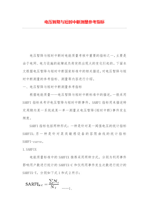
一、电压暂降与短时中断测量参考指标根据电能质量——电压暂降与短时中断标准中的描述,一般采用SARFI指标来考评电压暂降与短时中断事件。
SARFI指标用来描述特定周期内某一系统或某一单一测量点电压暂降(短时中断)事件发生频度。
SARFI指标包括两种形式:一种是针对某一阈值电压的统计指标SARFIX;另一种是针对某类敏感设备的容限曲线的统计指标SARFI-curve。
1.SARFIX电能质量标准中的SARFIX推荐采用两种方式,分别为利用事件影响用户数进行统计的SARFIX-C和仅利用事件发生次数进行统计的SARFIX-T,分别如下式1和式2所示:……1、式中:X——电压方均根阈值,X可能的取值为90、80、70、50或10等,用电压方均根值占标称电压的百分数形式表示,即为X%;当X<100时,Ni为第i次事件下承受残余电压小于X%的电压暂降(或短时中断)的用户数;NT——所评估测点供电的用户总数。
(2)式中:X——电压方均根阈值,X可能的取值为90、80、70、50或10等,用电压方均根值占标称电压的百分数形式表示,即为X%;当X<100时,Ni为第i次事件下承受残余电压小于X%的电压暂降(或短时中断)的用户数;DT——监测时间段内的总天数;D——指标计算周期天数,可取值30或365,对应指标分别表示每月或每年残余电压小于X%的电压暂降(或短时中断)的平均发生天数,D≤DT。
2.SARFI-curveSARFI-curve指标是统计电压暂降(短时中断)事件超出某一类敏感设备容限曲线所定义的区域的概率,不同的容限曲线对应不同的SARFI-curve指标。
电压暂降科普之四:电压暂降特征

电压暂降科普之四:电压暂降特征从物理现象看,电压暂降是母线电压方均根值下降至额定电压的90%~10%,持续0.5周波~1min的扰动事件。
相对于谐波、三相不平衡、电压波动与闪变等平稳电能质量扰动,电压暂降、短时电压中断、电压暂升等为非平稳扰动。
前者需外部人为干预后才能消失,后者会自动消失。
因此,前者被称作扰动现象或连续型扰动,后者被称作扰动事件或事件型扰动。
区分两者的关键在于是否需要人工干预才能消失,这样,便于工程技术人员理解。
为了理解和分析电压暂降事件,用恰当的电压暂降特征刻画暂降事件是基础。
1、刻画形式电压暂降事件的本质特性是电特性,表现为电压突然降低然后自动恢复的电压事件,表现为事件过程中电压随时间在持续较短时间内发生突然降低,然后突然恢复两次变化,可用三相电压瞬时值、有效值随时间变化的波形图、相量图、三相电压表达式等形式刻画。
以三相对称电压暂降为例,表现形式如图1、图2。
图1三相对称电压暂降瞬时值波形图和有效值波形图图2三相对称电压暂降相量图三相对称电压暂降的数学表达式如下,其中,V为发生电压暂降相的电压幅值。
其中,电压暂降事件的瞬时值波形图和有效值波形图,均能直观地刻画电压暂降事件中电压随时间的变化,而相量图和数学表达式是对电压暂降事件中某瞬间电压的描述。
2、暂降特征暂降特征是人们对暂降事件的客观理解和认识,是由人定义的用于描述和刻画电压暂降事件的物理量。
根据刻画目的、认知程度的不同,刻画电压暂降事件时采用的特征也不同。
根据需要和认知程度,用于刻画电压暂降事件的特征有多个,通常可用合理的特征向量刻画。
刻画电压暂降的特征向量中的特征主要有:暂降幅值(剩余电压)、暂降持续时间、暂降频次等。
其中,暂降频次是对某母线或系统暂降次数的统计,是对单一暂降事件的统计量,很多文献和著作中未当作电压暂降特征,但从全面刻画电压暂降事件的角度,尤其是需要分单一事件、节点和系统等不同层面进行电压暂降及其严重程度的刻画时,将暂降频次作为特征之一,具有一定的合理性。
电压暂降标准
电压暂降标准
电压暂降是指供电系统在短时间内电压短暂下降的现象。
为了保护电气设备和维护供
电系统的稳定运行,制定适当的电压暂降标准是必要的。
根据相关国际标准和经验,以及我国电力系统特点,制定以下电压暂降标准:
1. 电压暂降持续时间:电压暂降持续时间应在毫秒级或微秒级,一般不超过20毫秒。
暂降时间过长会对设备的正常工作产生不利影响。
2. 电压暂降幅度:电压暂降幅度应根据不同用途的电气设备而定。
对于一般工商业
用户,电压暂降幅度应保持在正常运行电压的90%~95%之间。
对于特殊需求的用户,应根
据实际情况制定合理的暂降幅度。
3. 电压暂降频率:电压暂降频率应尽量控制在每年不超过一次或更少。
频繁的电压
暂降会导致设备工作不稳定,给用户带来不便。
4. 电压暂降警示:供电企业应建立电压暂降警示机制,及时向用户通报电压暂降情况,并提供相应的预防和应对措施。
用户也应做好设备的保护措施,以应对可能出现的电
压暂降。
5. 监测与处理要求:供电企业应建立完善的电压暂降监测系统,及时发现和处理电
压暂降问题。
对于各类电压暂降事件,供电企业应及时跟进,追究责任,并采取相应的纠
正措施。
以上是一份电压暂降标准的概括,供电企业和用户在实际操作中应结合自身情况进一
步细化和明确具体的标准要求。
这将有助于保障供电系统的稳定运行,减少设备损坏和用
户用电不便,提高电能利用效率。
电压降计算方法
电压降计算方法电压降计算方法电缆电压降对于动力装置,例如发电机、变压器等配置的电力电缆,当传输间隔较远时,例如900m,就应考虑电缆第一电压的“压降”问题,否那么电缆采购、安装以后,方才觉察因未考虑压降,导致设备无法正常启动,而因此造成工程损失。
一.电力线路为何会产生“电压降”?电力线路的电压降是因为导体存在电阻。
正因为此,所以不管导体采用哪种材料〔铜,铝〕都会造成线路一定的电压损耗,而这种损耗〔压降〕不大于本身电压的5%时一般是不会对线路的电力驱动产生后果的。
例如380V的线路,假如电压降为19V,也即电路电压不低于361V,就不会有很大的问题。
电压降△U=IR<5%U到达要求 220*5%=11V 380*5%=19V二.在哪些场合需要考虑电压降?一般来说,线路长度不很长的场合,由于电压降非常有限,往往可以忽略“压降”的问题,例如线路只有几十米。
但是,在一些较长的电力线路上假如忽略了电缆压降,电缆敷设后在启动设备可能会因电压太低,根本启动不了设备;或设备虽能启动,但处于低电压运行状态,时间长了损坏设备。
较长电力线路需要考虑压降的问题。
所谓“长线路”一般是指电缆线路大于500米。
对电压精度要求较高的场合也要考虑压降。
三.如何计算电力线路的压降?一般来说,计算线路的压降并不复杂,可按以下步骤:1. 计算线路电流I公式:I= P/1.732×U×cosθ其中: P—功率,用“千瓦” U—电压,单位kVcosθ—功率因素,用0.8~0.85 2 .计算线路电阻R 公式:R=ρ×L/S其中:ρ—导体电阻率,铜芯电缆用0.01740代入,铝导体用0.0283代入L—线路长度,用“米”代入S—电缆的标称截面3.计算线路压降公式:ΔU=I×R举例说明:某电力线路长度为600m,电机功率90kW,工作电压380v,电缆是70mm2铜芯电缆,试求电压降。
解:先求线路电流II=P/1.732×U×cosθ=90÷〔1.732×0.380×0.85〕=161(A)再求线路电阻RR=ρ×L/S=0.01740×600÷70=0.149(Ω)如今可以求线路压降了:ΔU=I×R =161×0.149=23.99〔V〕由于ΔU=23.99V,已经超出电压380V的5%〔23.99÷380=6.3%〕,因此无法满足电压的要求。
电压暂降
医疗器械——暂降引起设备不正常工作影响诊断、治疗、
手术进行,甚至危及到病人的生命。
6.电压暂降的抑制
很明显,为解决或减缓设备敏感度问题,应该从消除或减少设备遭受电 压暂降的机会和增强设备本身对暂降的耐受能力两方面入手。 因此,设备对电压暂降的敏感度问题涉及电力部门、用户和设备制造商, 需要三方协力合作,共同解决。 1.供电系统方面 2.用户方面
产线管理 由于无序断电和上电,暂降导致损坏部件或加工设 备以及数字控制设备需重新设臵控制流程; 暂降影响机器人电焊工的焊接质量,甚至需要重 新回炉或电焊程序的重启; 暂降使得喷漆线突然停止,在火炉控制重启前, 需要30min净化空气控制系统。
。
暂降导致停产的更多时间是花费在整个生产线再 启动上(有报道讲,由于4个周波的电压暂降,需 要72min才能恢复生产线工作,造成损失可达700, 000$) 暂降造成商业与民用建筑中的电梯、自动消防与报警系统中止工作……
设备不能发挥应有的功能,或只能在有限的范围内运行。 设备性能降低,在极端情况下完全停止工作。 更为严重的是,工艺流程重启动造成的连带影响;
5.电压暂降的危害
随着现代电力工业的快速发展和系统中用电负荷结构 的重大变化,暂态电能质量问题引发的事故越来越多, 电压暂降问题愈发凸显,电压暂降造成生产线上电机 停机、变频器失压保护动作、可编程逻辑控制器 (PLC)失灵、计算机存储数据丢失等事故也越来越 多,给用户带来巨大的经济损失。
图b:大型电机启动
就现象可见,电压暂降并不是新问题。但 是,由于其危害和影响十分突出,它却成为 近年来日益引起电工界关注的最重要的电 能质量问题.
电压暂降对供电条件的影响
电压暂降的起因是由于事件引起的功率(尤其是无功功 率)大幅度变化,其波及面较大。