instron8800系列疲劳试验机系统
海德汉TNC 620 HSCI Gen 3驱动器紧凑型数控系统说明书

TNC 620 HSCIGen 3驱动器镗铣类机床的紧凑型数控系统面向机床制造商07/2021TNC数控系统带驱动系统一般信息TNC 620•铣、钻和镗机床的紧凑型数控系统•轴数:8个控制环,其中2个可配置为主轴•用海德汉变频器系统并优选使用海德汉电机•全数字化HSCI接口和EnDat接口•尺寸紧凑•CF闪存卡•海德汉Klartext对话式和G代码(ISO)编程•标准铣、钻和镗加工循环•测头探测循环•程序段处理速度快(1.5 ms)19英寸显示屏(纵向)版•一体化的显示屏、键盘和主机(MC8410)•显示器下端为键盘•多点触摸式操作15英寸显示屏(横向)版•一体化的显示屏和主机(MC8420)•独立的键盘单元•多点触控操作系统测试海德汉数控系统、功率模块、电机和编码器通常是完整系统的组成部件。
因此,需要综合测试整个系统,而不能仅仅测试各单独设备的技术性能。
损耗件海德汉数控系统中含易损件,例如、后备电池和风扇。
标准本产品遵循的标准(ISO,EN等),请见样本中的标注。
注意Intel、Intel Xeon、Core和Celeron是Intel Corporation的注册商标。
有效性本文所述功能和技术参数适用于以下数控系统和NC数控软件版本:TNC 620,NC数控软件版本817600-08(需出口许可证)817601-08(无需出口许可证)本样本是以前样本的替代版,所有以前版本均不再有效。
如有变更,恕不另行通知。
要求有些技术参数对机床的配置有特别要求。
请注意,有些功能还需机床制造商开发专用PLC程序。
功能安全特性(FS)如果未明确区分标准部件与FS部件(FS = 功能安全特性),所介绍的信息适用于这两类部件(例如, TE 735,TE 735 FS)。
对于带功能安全特性的部件,在其产品标识的最后带标识符“(FS)”,例如,UEC 3xx (FS)2目录TNC数控系统带驱动系统2一览表4HSCI控制部件16附件23电缆概要37技术说明44数据传输和通信73安装信息77主要尺寸79一般信息101其它海德汉数控系统103主题索引104请注意技术参数表内的页码。
880-NSL 培训

Process Instruments Business UnitProcess Instruments Business Unit克劳斯反应过程1、克劳斯炉燃烧2、催化床催化能量当反应后H2S和SO2的比值为2:1时为最佳3、克劳斯炉中可能还存在的其他反应:羰基硫的形成(通常是非常小部分)二硫化碳的形成(通常是非常小部分)透过测量池A= 吸光度ε= 摩尔吸收率b= 光路长度c= 吸光介质的浓度I0=原始光强I =透过测量池后的光强T=透过率吸光介质c的浓度光路长度bProcess Instruments Business Unit2分光镜测量池长b注意:280nm 波长的光在经过测量池后其强度已减弱,但400nm 波长的光的强度无变化400nm 参考滤光片只容许400nm 的光通过280nm 测量滤光片只容许280nm 的光通过参考检测器测量检测器灯准直镜准直镜光源灯光电二极管测量池记录仪逻辑放大器控制器聚光镜滤光片测量波长参考波长样气出样气进分光镜聚光镜光电二极管光路组件光路组件截面图Process Instruments Business UnitProcess Instruments Business Unit检测器电路板光强高低低吸光度高吸光度转换计数每个单位的吸光度对应2V电压总范围是5个单位的吸光度模数转换(A/D转换)Process Instruments Business Unit压力变送器键盘两通电磁阀压力表三通电磁阀减压阀除雾器温度传感器加热器Process Instruments Business Unit除雾器温度传感器(RTD 加热器灯的触发器除雾器衬垫除雾器组件特氟纶衬垫测量箱温度传感器(RTD )进样阀回样阀吸气器(文丘里管)Process Instruments Business UnitProcess Instruments Business Unit正压通风排放口压差开关温控器灯泡电容橡胶套触发器继电器板接口板电源板/CPU 板电信号接线图气样流程图880-NSL分析仪时序图控制器的显示SO2浓度(显示参数1)H2 S浓度(显示参数2)测量池压力(显示参数7)系统信息/报警Process Instruments Business Unit同时按这两个键复位仪器系统菜单出厂原始参数表Process Instruments Business Unit。
nCode培训 实用疲劳理论

实用疲劳理论
Quiz 1:
• How can you break a metal spoon?
实用疲劳理论
• 材料的物理性能 • 疲劳载荷 • 应力寿命(S-N)法 • 局部应变法(e-N)
1
© 2007 nCode
Quiz 2:
• How can you break a ceramic spoon?
火车出轨
什么是金属疲劳?
Quiz 4: • Can you name a metal
fatigue failure you experienced?
汽车零部件失效
• Truck frame • Manifold • Bracket • Crankshaft • Brake • Exhaust pipe • Wheel •…
43
Note that: 6.895 x ksi = MPa
© 2007 nCode
Load, P Engineering Stress, S
Monotonic Loading
Load Time Curve
Engineering Stress – Strain Curve
Time, t
Engine er ing Stress S = P A0
发展了旋转弯曲疲劳试验 ,S-N曲线及疲劳极限概念 • 1886年,Bauschinger 首先确证了应力-应变滞回线 • 1903年,Ewing 和 Humphrey 证明结晶理论是不正确的,
指出疲劳是由于塑性变形所引起 • 1910年,Bairstow 调查了应变循环中的应力-应变响应,
提出了循环硬化和循环软化概念 • 1920年,Griffith 研究了玻璃中的裂纹,由此诞生了断裂力学
ATC880英文说明书
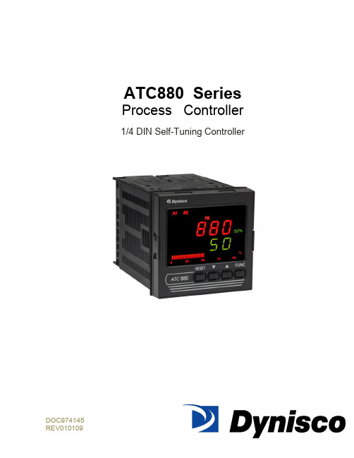
ATC880 SeriesProcess Controller1/4 DIN Self-Tuning ControllerDOC974145TABLE OF CONTENTSQUICK START INSTRUCTIONS (5)1.0 INTRODUCTION (8)2.0 SPECIFICATIONS (9)2.1 Mechanical Specifications (9)2.2 Main Power Supply & Environmental Specification (9)2.3 Display Specification (10)2.4 Primary Input Specification (11)2.5 Secondary Input (12)2.6 Pressure & Remote Set Point Inputs Common (13)2.7 Digital Input (14)2.8 Alarms (14)2.9 Optional Serial Communication Interface Specification (15)2.10 Control Output Specification (15)2.11 Retransmission Output Specification (16)2.12 Control and Retransmission Outputs Common Specification (16)2.13 Control Algorithm Specification (16)2.14 Opto-isolated Digital Input Specification (18)3.0 UNPACKING & DIMENSIONAL INFORMATION (19)3.1 Unpacking (19)3.2 Dimensional Information (19)3.3 Block Diagram (19)4.0 MOUNTING AND WIRING (21)4.1 Terminal Assignments and ratings (24)4.2 Terminal Cross Reference With Former Dynisco Model ATC770 (26)5.0 START-UP PROCEDURE (28)5.1 Configuration (28)5.2 Parameters (28)5.2.1 Getting Ready: (28)5.2.2 Keyboard Description: (28)5.2.3 Operating Mode Description: (30)5.3 Setting the Instrument‘s Basic Configuration (30)5.3.1 Setting the Shunt Calibration: (31)5.3.3 Setting the Logic Input Status (optional) (31)5.3.4 Setting the Status of Auto/Manual Selection (optional) (31)5.3.6 Setting the Line Frequency (32)5.3.7 Setting the Display Filter (32)5.4 Setting the Remote Set Point Input/Seconday Input (Optional) (33)5.4.1 Setting the Remote Set Point/Secondary Input Voltage or Current (33)5.4.2 Setting the Remote Set Point (RSP) Input Failsafe Mode (33)5.4.3 Setting the Remote Set Point Limits (33)5.4.4 Setting the Local Remote Set Point Selection (34)6.0 CONFIGURATION (35)6.1 Primary Input Setup (35)6.1.1 Setting the Primary Input Type for a Strain Gage Transducer (35)6.1.2 Setting the Shunt Calibration for Strain Gage Transducers and Amplified Transmitters (35)6.1.3 Setting the Primary Input Type for an Amplified Transmitter (35)6.1.4 Setting the Primary Input Full-Scale Value (36)6.1.5 Setting the Primary Input Low-Scale Value (36)6.1.6 Setting the Primary Input Decimal Place (37)6.1.7 Setting the Primary Input Failsafe Mode (37)6.2 Setting the Alarms: (37)6.2.1 Setting What the Alarm will Monitor (Alarm Input Channel Link): (38)6.2.2 Setting Alarm Type: (38)6.2.3 Setting the Filtering for Alarms: (38)6.2.4 Setting the Hysteresis for Alarms: (39)6.2.5 Setting the Reset Mode for Alarms: (39)6.2.6 Setting the Failsafe Mode for Alarms: (39)6.2.7 Setting the Alarms Threshold Values: (40)6.2.8 Setting the Alarms Mask Reset Type: (40)6.3 Retransmission Output Setup (40)6.3.1 Selection of the Retransmission Output (40)6.3.2 Setting the Retransmission Output Range (40)6.3.3 Setting the Retransmission Output Range High (41)6.3.4 Setting the Retransmission Output Filter (41)6.4 Setting the Control Output: (41)6.4.1 Setting the Control Output Voltage or Current: (41)6.4.2 Making the Control Output Direct/Reverse Selection: (41)6.4.3 Setting the Control Output Limit: (42)6.4.4 Setting the Control Output Manual Mode Indication: (42)6.4.5 Setting the Control Output Display: (42)6.5 Setting the Security Codes: (43)6.5.1 Setting the Security Code for Level A (43)6.5.2 Setting the Security Code for Level B (43)6.5.3 Setting the Security Code for Level C (43)6.6 Configure by Remote PC (Configuration Port Interface or CPI) (44)6.7 Configure Differential Control (45)7.0 OPERATION (51)7.1 Primary Input Calibration (51)7.1.1 Calibration of Pressure Transducers with Internal Shunt Resistor (51)7.1.2 Calibration of Amplified Pressure Transmitters with Internal Shunt Resistor (51)7.1.3 Calibration of Pressure Transducers equipped with External Shunt Resistors (51)7.1.4 Calibration of Analog Inputs Using a Pressure Calibration Source (52)7.1.5 Calibration of the ATC880 to Calibrated Linear Analog Input (52)7.2 Start-Up and Engaging SMART (53)7.2.1 Setting the Process Set Point (53)7.2.2 Engaging SMART (53)7.2.3 Engaging Automatic Control (53)7.3 The Tuning Mode (53)7.3.1 Selecting the Type of Control (54)7.3.2 Engaging the Tuning Algorithm (ATC880 in Manual Mode) (54)7.3.3 Viewing the Tuning Algorithm Parameters (54)7.3.4 Engaging the Adaptive Tuning Algorithm (ATC880 in Automatic Mode) (56)7.3.5 Automatic Stand-By in the event of a Process Upset (56)7.3.6 Automatic or Manual Start-Up (57)7.3.7 Manual/Automatic Transfer (57)7.3.8 Tuned Parameters, After SMART ―tuning‖ (58)8.0 INSTRUMENT CALIBRATION (60)8.1 General Calibration Procedure (60)8.2 RS-485 (Optional) (62)8.2.1 Serial Communication Interface Address (62)8.2.2 Protocol Type (62)8.2.3 Communication Type (62)8.2.4 Communication Baud Rate (62)8.2.5 Setting the Status of Auto/Manual Selection (optional) (63)9.0 ERROR CODES (64)9.1 Error Codes and Troubleshooting (64)9.2 ―OPEN‖ Error Code and Troubleshooting (66)9.3 Instrument Maintenance (66)10.0 NORMATIVE REFERENCES (67)11.0 PARAMETER GROUP MENUS (69)11.1 Group 1 Parameters (71)11.2 Group 2 Parameters (73)11.3 Group 3 Parameters (78)11.4 Group 4 Parameters (82)11.5 Group 5 Parameters (87)11.6 Group 6 Parameters (89)11.7 Group 9 Parameters (90)12.0 PID CONTROLLER DEFINITIONS (92)13.0 WARRANTY AND SERVICE (94)QUICK START INSTRUCTIONSMountingPrepare panel cutout to dimensions shown below (1A).If more instruments are mounted in the same panel near together, maintainthe distances between one instrumento to another like as in the figure.Slide the rubber gasket (1) over the case.Slide the instrument case into the cutout (2,1A).Attach the panel mounting hardware tightening the threaded rod (3) for asecure fit and with a screwdriver, turn the screws with a torque between 0.3and 0.4 Nm.WiringRefer to Section 4 for wiring/connections and terminal diagramConnect the wires from transducer cable as shown in the terminal diagram,turn the screws with a torque between 1.0 and 1.2 Nm..Connect final control device.Connect alarm(s) if applicable. Note that alarm defaults are High, ReverseActing for alarms 2 & 3 –alarm 1 is low inhibited.Connect power to the appropriate terminals as shown.1AScalingApply power to the instrument; Upper display will give a reading near zero.Lower display will read the manual output %.Press key until the Upper display reads NONE and lower display readsGROUP.If your transducer is not a 10,000-psi model, select GROUP3 using the Uparrow, enter with function key.Lower display reads PI.FSV (Full Scale Value), and the upper display reads10,000. Note: If your transducer is a 10,000-psi model skip next two steps.Scroll to GROUP and select 2.Using the Down arrow key set the appropriate Full Scale Value for yourtransducer.Enter using the key to scroll until GROUP legend appears again.Using Up arrow key, select GROUP2. Enter with key.Follow instructions for Calibration and Operation in Step 4 of Quick Start Calibration and OperationLower display reads ZERO.C and upper display reads OFF. Be suretransducer is at operation temperature and that no pressure is applied.Change upper display to ON by using the Up arrow key. Enter with the key. After a few seconds, the lower display will show SPAN.C and upper display will show OFF.Change upper display to ON using Up arrow key. Enter with thekey. In a few seconds lower display shows SMART and upper display showsOFF. Calibration is complete.Using the key, scroll to the GROUP display. Enter 1 with the Uparrow, and enter with the key. Instrument shows 0 on upper displayand SP on lower display.Set Process Set point. Press twice.Set Alarm 1, 2, 3 thresholds (if applicable) by pressing . Changethreshold with the up and down keys.Press twice. Lower display will read GROUP, and upper display willread none.Press key. Upper display will read 0 +/- 10 process pressure, lowerdisplay will read 0. This is control output %.Be sure process is at operating temperature.Utilizing up and down keys, manipulate the output % until the upperdisplay is reading at approximately the set point.Press key until lower display reads GROUP. Select group 2.Press key three times. Lower display reads SMART and upper displayreads OFF.Using up arrow key, turn SMART function to on. Enter with key.SMART LED will flash and a countdown will begin as the controller arrives atinitial P&I (D) parameters.Return to GROUP none and observe that the value in the upper display is theactual set point you wish to control.When the SMART LED has stopped flashing, press and hold the A/M key forat least 5 seconds. The manual LED will extinguish, and you will be inautomatic control mode.Again, return to GROUP2 and select SMART. Turn the function on with theup arrow, and enter with the . This will activate the Adaptive Tune algorithm, and will maintain the correct P&I (D) parameters for the process. Itwill remain on until manually turned off. It will also come on anytime theATC880 is the automatic control mode.Return to GROUP,None, and observe the process. The set point may beadjusted in GROUP1 while the controller is in automatic mode.Operator may alternately display Output %, Set Point, Deviation, Peak Value,or RPM by pressing the up arrow key.The preceding Quick Start instructions are the basic settings required to install, wire, and get the controller operating. Please refer to the complete installation and operation manual for additional functions. Questions on your transducer will be addressed in the manual included with your transducer.References to Profibus features and instructions should be ignored. Profibus is being considered for a future line expansion and has been accommodated in the current design.1.0 INTRODUCTIONThe ATC880 Pressure/Process Controller is a microprocessor-based instrument with the capability of controlling an extruder or other process using an advanced proprietary SMART self-tuning algor ithm. The input is user configurable to be 350Ω Strain Gage, high-level voltage or high level current. The voltage or current inputs are compatible with many process transmitter combinations. Three fully programmable alarms and an analog retransmission output are also included as part of the standard ATC880 package.Five groups of configuration parameters are available from the keyboard, and are protected by three levels of user definable software locks. (A sixth group of read-only parameters can also be viewed) In the programming mode the lower display will show the parameter being displayed, and the upper display will show its value. In the operating mode, the upper display will show the process variable, and the lower display offers the choice of displaying set point, deviation from set point, output %, RPM or peak. In addition, a red LED bar graph presents an analog representation of the main input (process variable), as well as indication of the alarm set points. The alarms are shown relative to the span of process and are indicated as missing or present bars relative to the process input.References to Profibus features and instructions should be ignored. Profibus is being considered for a future line expansion and has been accommodated in the current design.WARNING NOTE: The user should be aware that if this equipment is used in a manner not consistent with the specifications and instructions in this manual, the protection provided by the equipment might be impaired.Product Codes (ordering options)Note: UL pending only for Power Code Voltage equal to 5 (24Vac/dc, switching)2.0 SPECIFICATIONS2.1 Mechanical SpecificationsCase: Polycarbonate Black color Self-extinguishing degree V0 according to UL 94Front Panel: Designed and verified for IP65 and NEMA 4X for indoor location Installation: Panel mountingRear Terminal Block: 46 screw terminals with rear safety cover2.2 Main Power Supply & Environmental SpecificationMain Power Supply: From 100 to 240Vac (-15% to 10%), 50/60Hz switching. Option: 24Vac/dcPower supply variation: From -15% to 10% (for 100 to 240Vac). From 14 to 32 Vac/dc (for optional 24Vac/dc).Power Consumption: Max 22VA at 50Hz or Max 27VA at 60Hz for Main Power Supply from 100 to 240 VacInsulation Resistance: 100MΩ @500VdcDielectric Strength: 1500V rms for 1 min, 1800V for 1 sec.Ambient Temperature: From 0 to 50°C. Ensure the enclosure provides adequate ventilationStorage Temperature: From -20 to 70°CHumidity: Max 85% RH non-condensingAltitude: This product is not suitable for use above 2000m (6562ft) or in explosive or corrosive atmospheresWatchdog: Hw/Sw is provided for automatic restartAgency Approvals: UL File # 193253Self-Certification: CEElectromagnetic Compatibility:The instrument is compliant with the European Directive 2004/108/CE according to Product Standard EN 61326-1.Emission limit:class A – group 1 ISM for equipment suitable for use in allestablishments other then domestic and those directly connected to a lowvoltage power supply network which supplies buildings used for domesticpurposes.Immunity:Electrostatic discharge (according to EN 61000-4-2):contact discharge = 4kV; air discharge = 8kVRadio-frequency electrical magnetic (according to EN 61000-4-3):EM field (amplit. mod.) = 10 V/m (80MHz to 1 GHz);3V/m (1,4 GHz to 2 GHz);1 V/m (2 GHz to 2,7 GHz)Electrical fast transient/burst (according to EN 61000-4-4):AC Power = 2kV;I/O Signal/Control = 2kV (5/50 ns, 5 kHz);I/O Signal/Control connected directly to mains supply = 2kV (5/50 ns, 5kHz)Surge (according to EN 61000-4-5):AC power = 1kV (Line to Line) / 2kV (Line to GND);I/O Signal/Control = 1kV (Line to Line) / 2kV (Line to GND)Radio frequency common mode (according to EN 61000-4-6):AC Power = 3 V (150kHz to 80 MHz);I/O Signal/Control = 3 V (150kHz to 80 MHz)Voltage dips/short interruptions (according to EN 61000-4-11):0% during 1 cycle; 40% during 12 cycles; 70% during 30 cyclesThis equipment is intendent for use in an industrial location. There may be potential difficulties ensuring electromagnetic compatibility in other environmental due to conducted as well as radiated disturbances.Safety Requirements:The instrument is compliant with the European Directive 2006/95/CE according to Reference Standard EN 61010-1 for installation category I and pollution degree 2 Installation category CAT I: Voltage transients on any power connected tothe instrument must not exceed 1.5kV. Pollution degree 2: Conductive pollution must be excluded from thecabinet in which the instrument is mounted.2.3 Display SpecificationDisplay: LED technology, custom type.Upper Digits: Red color, 5 numeric digits, 7 segments with decimal point 13.2mm high. Lower Digits: Green color, 5 alphanumeric digits (British flag), 14 segments with decimal points, 11.3 mm high.Bar Graph: Red color, 35 segment with 3% resolution. Displays continuous bar graph to indicate the measured variable of the main input (0-100% full scale). Alarm set point values displayed. Last segment blinks for pressure greater than full scale value. Indicators (Beacons):Red LED‘s annunciations:A1: Lit when alarm 1 is in alarm stateA2: Lit when alarm 2 is in alarm stateA3: Lit when alarm 3 is in alarm stateREM: Lit when device is controlled by serial link0-25-50-75-100-%: These six LEDs are always on to improve the bar graphindication.SMRT: Flashing when the first step of SMART algorithm is activated. Lit whenthe second step of SMART algorithm is activatedMAN: Lit when device is in manual modeRSP: Lit when Remote Set Point is selectedKg/cm2, PSI, Bar, MPa: Engineering unit for the pressure input. These fourbeacons are located within the display window, between the numeric digits andthe alarm beacons.Green LED‘s ann unciations:SP: Lit when lower display shows the Set PointPEAK: Lit when lower display shows the peak valueDEV: Lit when lower display shows the deviation (Measured Variable minus SetPoint)OUT%: Lit when lower display shows the Output Value (absolute value with 0.1% resolution)RPM: Lit when lower display shows the Output Value scaled to RPM2.4 Primary Input SpecificationMain Input: Selectable between strain gage and linear by software configuration.Strain Gage Input: From 340 to 5000Ω, 1-4 mV/V. Excitation 10V +/- 7%. 5 wires connection.Linear Input: Selectable between 0-5Vdc, 0-10Vdc, 0-20mA, 4-20mA.Input Signal: -25/125% of full scale (approximately –10 / 50mV).Shunt Calibration: With or without shunt resistor (value programmable from 40.0 to100.0%).Zero Balance: ±25% of full scale (approximately ± 10 mV).Auxiliary Power Supply: 24Vdc / 1.5W power supply for two or four wire transmitter. Input Impedance: <10Ω for linear current input;>165KΩ for linear voltage inputInput Protection: Open circuit detection for strain gage (on signal and excitation wires) and 4-20mA inputs; it is not available for 0-5Vdc, 0-10Vdc and 0-20mA. Up or down scale keyboard programmable.Sampling time: 50mS typical.Display Update Time: Selectable: 50, 100, 250 or 400mS.Engineering Units: Dedicated beacons within the display window.Calibration Mode: Field calibrations (zero and span) are applicable for both strain gage and linear input. Moreover it is possible to delete the field calibration done by the end user and to restore original factory calibration values.Input resolution: 4000 counts.Full scale value Resolution10/4000 1 count4002/8000 2 counts8005/20000 5 counts20010/40000 10 counts40020/80000 20 counts80050/99950 50 countsDecimal Point: Settable in any position of the display or none at all.2.5 Secondary InputSecondary input: Selectable among 0-5Vdc, 0-10Vdc, 0-20mA, 4-20mA or strain gage (optional).Function: Second sensor for the measurement of a differential pressure (in case of strain gage or linear input); remote set point (only linear inpu).Input Protection: Open circuit detection for strain gage (on signal and excitation wires) and 4-20mA inputs; not available for 0-10Vdc, 0-5Vdc and 0-20mA inputs. Up or down scale keyboard.Input Impedance:< 10Ω for linear current input> 165KΩSampling Time: Remote set point input is selectable among 100, 200, 500 or 1000mSe; differential pressure is 50 mS, typical.Display update: At each sample.Input Resolution with Linear Input: 4000 counts.Low/High Scale Values: Secondary input of a differential pressure: freely settable, but with the same resolution and decimal point position of the primary pressure input. Remote set point: settable from 0 to pressure input full scale value with the same resolution and decimal point position of pressure input.NOTE: This input is not isolated from main input. A double or reinforced insulation between instrument output and power supply must be guaranteed by the external device.2.6 Pressure & Remote Set Point Inputs CommonCommon Mode Rejection Ratio: >120dB @50/60HzNormal Mode Rejection Ratio: >60dB @ 50/60HzStrain gage input: From 340 to 5000Ω, 1-4 mV/V. Excitation 10V +/- 7%. 5 wires connection.Input signal: -25/125% of full scale (approximately -10/50mV).Shunt calibration: With or without shunt resistor (value programmable from 40.0 to 100.0%), the same setting will be used for both inputs (main and secondary) when the differential pressure measurement is selected.Zero balance: +/- 25% of full scale (approximately +/- 10mV).Reference accuracy: +/- 0.1% FSV +/-1 digit @ 25 +/- 1°C and nominal power supply voltage.Operative accuracy: temperature drift: < 300 ppm/K of full span for current, voltage and strain gage input.Zero and span calibration: If differential input used, there is no relation between the calibration of the two single sensors; each input is provided with its own zero and span calibration parameters.2.7 Digital InputDigital input: One input from contact closure (voltage free). It is marked as ―Reset‖ on rear panel, contacts 23 and 24. It may be keyboard programmable for the following functions:• alarm reset• peak reset• alarm and peak reset• zero calibration of the primary input• zero calibration of the primary input, alarm and peak resetNOTE: This input is not isolated from main input. A double or reinforced insulation between instrument output and power supply must be guaranteed by the external device.Opto-isolated Digital Input: Four optional digital inputs are provided for control purposes. The interface circuit is opto-isolated with respect to the CPU and analog inputs.DIG1: This contact acts as an automatic / manual switch, if it is enabled by the proper parameter (closed means manual mode, open means automatic mode).DIG2: Control output value increaseDIG3: Control output value decreaseThese two contacts are used to increase / decrease the output value with a linear, not exponential, rate of change (about 20 seconds for a full scale variation from 0 to 100%). DIG4: This contact is used to switch the controller from automatic to manual mode setting to zero the control output. When this logic input is closed the transfer from manual to automatic mode by the front panel is inhibited while the user may modify the control output. To return to automatic mode the logic input should be de-activated.2.8 AlarmsAlarm Outputs: 3 standard alarms (AL1, AL2 and AL3).AL1 and AL2 Contacts: 1 SPDT 2A max @ 240Vac resistive load.AL3 Contacts: 1 SPST 2A max @ 240Vac resistive load.Contact Protection: Varistor for spike protection.Alarm Type: Each alarm is keyboard programmable for:• Process / Deviation / Band• High / Low / Low inhibited on start up• Auto / Manual resetAlarm Mask: The alarm mask may be restored using the keyboard parameter (AL.MSK). Moreover the alarm mask of deviation and band alarms is restored at set point change and during set point ramp.Excitation Type: Keyboard configurable for each alarm: relay coil energized in no alarm condition (failsafe) or relay coil energized in alarm condition (non-failsafe). The default condition is failsafe.Threshold: From 0 to 110% Full Scale (the threshold may be limited due to the selected full scale value).Hysteresis: Keyboard programmable for each alarm; from 0.1% to 10.0% of span or 1 Least Significant Digit (whichever is greater) for each alarm.Alarm Filter: Selectable from the following values: OFF, 0.4S, 1S, 2S, 3S, 4S, 5S.Alarm Update Time: At every input conversion.2.9 Optional Serial Communication Interface SpecificationSerial Interface: RS-485 type. Opto-isolated.Protocol Type: Modbus/Jbus (RTU mode).Type of Parameters: Run-time and configuration are available by serial link.Device Address: From 1 to 255NOTE: The physical interface can only support up to 31 devices for each segment.Use multiple segments for more than 31 devices.Baud Rate: 600 up to 19200 baud.Format: 1 start bit, 8 bits with or without parity, 1 stop bitParity: Even/Odd.2.10 Control Output SpecificationControl Output: Opto-isolated from CPU input and output circuits.Type of Analog Output: Keyboard selectable between:•+ 0/10Vdc min load 5KΩ•– 10/+10 VDC min load 5KΩ•+ 0/5Vdc min load 5KΩ•+ 0/20mA max load 500KΩ•– 4/20mA max load 500ΩResolution: 0.1% in manual mode, 0.03% in automatic mode.Scaling: The output control value may be displayed in two modes:• from 0.0 to 100.0% (0.1% resolution)• from a low to a high limit selection from -10000 to 100002.11 Retransmission Output SpecificationRetransmission Output: Opto-isolated from CPU input and output circuits.Type of Analog Output: Keyboard selectable between:•+ 0/10Vdc min load 5KΩ, with under/overrange capability from -2.5 to 12.5V.•± 10Vdc min load 5KΩ, with under/overrange capability from -12.25 to 12.5V.•+ 0/5Vdc min load 5KΩ, with under/overrange capability from -1.25 to 6.25V.•+ 0/20mA max load 500Ω, with un der/overrange capability from 0 to 24mA (max. load 400Ω over 20 mA).• + 4/20mA max load 500Ω, with under/overrange capability from 0 to 24mA (max. load 400Ω over 20mA).Resolution: 0.1% of output modeScaling: The retransmission low and high limits are selectable from 0 to full scale input value. The two scaling values may be freely selectable within the above range. This allows for a direct or reverse output type.Output Filter: Selectable from the following values: OFF, 0.4S, 1S, 2S, 3S, 4S, 5S2.12 Control and Retransmission Outputs Common SpecificationReference Accuracy: ±0.1% of output span @ 25 ± 10°C and nominal line voltage. Linearity Error: <0.1% of output span.Output Noise: <0.1% of output span.2.13 Control Algorithm SpecificationControl Type: PID plus Integral Preload plus Anti-Reset WindupOutput Value Indication: Selectable between the following Modes:• Range 0/100.0%• Selectable with two calibrated values for RPM indication• In automatic mode either mode is available• In manual mode, a parameter is provided to select the first or second method of indication.SMART Algorithm: The SMART procedure is activated by setting the SMART Parameter to ON. In manual mode the controller will start the TUNE algorithm (SMRT led flashes), while in automatic mode it will enable the ADAPTIVE function (SMRT led lights steady).The SMART can select two types of procedures:1. The TUNE algorithm2. The Adaptive algorithmTUNE ALGORITHMTo implement the TUNE algorithm, set the instrument in manual mode and the select SMART ON. SMART will switch to OFF after the PID parameters (PB, TI, TD) are calculated (during this procedure the LED will be flashing). The basic concepts of the auto-tuning system are based on the open loop step response, for this reason the TUNE function may be activated only in the manual mode.The equivalent mathematical model of the process is characterized by three parameters: the gain, the time constant and the equivalent time delay. The power output of the controller is changed by a small step value. Then, the controller stores the process variable response. From the transient response, the controller estimates the three basic process parameters by means of the area‘s method. It applies these parameters, and re-runs the step process. When this is done, it calculates the final PID parameters.The step response is a convenient way to characterize this type of process dynamics because its model is based on the alteration of the behavior of the process and very accurately determining the response. It is capable of estimating the process parameters with high precision.ADAPTIVE ALGORITHMIn order to implement the adaptive algorithm, the instrument should be in automatic mode. Then change SMART to ON. In this case the ON will be remembered by the instrument even if the instrument was switched off.In order to deactivate the adaptive processes, return the SMART parameter to OFF. The ADAPTIVE is an on-line algorithm that ―observes‖ the measured value and l ooks for oscillation due to a variation of the load or the set point. When a significant pattern is―recognized,‖ the decision procedure starts to recalculate the PID parameters of the controller. While the ADAPTIVE procedure is enabled the PID parameters can only be monitored.AUTOMATIC STAND-BY: This function avoids overshoot due to temporary process。
X70M管线钢焊接接头CTOD断裂韧性研究
X70M管线钢焊接接头CTOD断裂韧性研究倪子涵;曹能;储双杰;刘硕【摘要】采用CTOD(裂纹尖端张开位移)试验对X70M直缝埋弧焊管焊接接头的焊缝中心、熔合线和热影响区进行断裂韧性测试,并使用OM、SEM和EBSD对CTOD试样裂纹扩展区的微观组织进行观察.结果显示,X70M直缝埋弧焊管焊接接头的CTOD断裂韧性为:焊缝中心良好,熔合线波动大,热影响区最佳.焊缝中心的组织细小均匀,断裂韧性稳定;熔合线附近的组织形态和晶粒大小差异大,大角度晶界比例较低,链状M-A组元诱发应力集中,造成CTOD特征值离散性大,并且出现薄弱点;等效热影响区中的针状铁素体含量增多,有利于提高韧性.【期刊名称】《宝钢技术》【年(卷),期】2016(000)006【总页数】7页(P47-53)【关键词】X70M管线钢;焊接接头;断裂韧性;裂纹尖端张开位移(CTOD)【作者】倪子涵;曹能;储双杰;刘硕【作者单位】上海交通大学,上海200240;宝山钢铁股份有限公司,上海201900;上海交通大学,上海200240;宝山钢铁股份有限公司,上海201900;宝山钢铁股份有限公司,上海201900【正文语种】中文【中图分类】TG142.4管道运输作为一种大规模输送石油和天然气的方式,为现代五大交通运输方式之一,具有经济、安全、不间断的特点。
为了提高管道的输送效率,减少管线的投资和运营费用,长距离输送管道向高压、大口径发展已成趋势,这无疑对管线钢的安全性提出了更严格的要求[1]1-6。
其中,材料的断裂韧性对管道的安全性有着显著影响,成为现阶段管线钢研究的一个重点。
裂纹尖端张开位移(CTOD,Crack Tip Opening Displacement)是指张开型裂纹的尖端在外力作用下所张开的距离,其大小反映了材料抵抗裂纹非稳定扩展的能力,成为评价管线钢结构安全可靠性的判据之一。
本文以X70M直缝埋弧焊管的焊缝中心、熔合线和热影响区3个部位的CTOD试样为研究对象,测试-10 ℃下的CTOD 特征值,探究焊接接头各部位断裂韧性的优劣及组织变化对各部位断裂韧性的影响,为工程应用提供理论参考。
万元及以上教学科研设备明细表
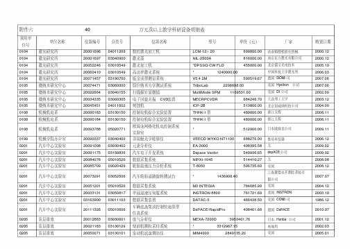
附件六 40万元及以上教学科研设备明细表领用单位号单位名称仪器编号分类号仪器名称型号单价(元)厂家购置日期0104 激光研究所20001696 04011209 数控激光加工机LCM-12×20 699800.00 济南铸锻机研究所械2000.12 0104 激光研究所20001697 03040900 激光器NIL-2500A 816000.00 南京东方激光有限公司2000.12 0104 激光研究所20052246 03010549 激光加工机*DPSSQ-CW FLD 455000.00 北京镭宝光电技术2005.10 0104 激光研究所20060410 03010549 高功率激光系统* 1240000.00 中国科技大学激光所2006.03 0104 激光研究所20071457 03190700 钣金成型测量系统V5.4 2M 590519.67 德国GOM公司2007.06 0105 微纳米研究中心20074471 03060000 原位纳米力学测试系统TriboLab 2298698.60 美国Hysitron公司2007.06 0105 微纳米研究中心20022664 03040155 扫描探针显微镜MultiMode SPM 1169531.60 美国DI公司2002.09 0105 微纳米研究中心20034335 03060305 电子回旋共振CVD装置MECRPCVDR 684246.70 大连理工大学2003.12 0105 微纳米研究中心20045451 04011602 刻蚀机ICP-2B 513800.00 北京创威纳科技公司2004.09 0108 机械机电系20090183 03130150 控制电机综合实验装置THHK-I型480000.00 浙江天煌2008.11 0108 机械机电系20090184 03130150 控制电机综合实验装置THHK-I型480000.00 浙江天煌2008.110108 机械机电系20093788 05020771 欧姆龙网络化机电控制系统实验室* 512900.00 日本欧姆龙公司2009.110199 机械学院办公室20090337 03040400 非接触光学轮廓仪VEECD WYKO NT1100 688276.00 维易科仪器2006.12 0201 汽车中心实验室20091098 03030402 元素分析仪EA-3000 408395.58 无2009.02 0201 汽车中心实验室20091175 03150836 汽车电子开发系统Dspace Vector 549936.65 dspACE公司2009.02 0201 汽车中心实验室20084078 05010526 数据采集系统NIPXI-1045 514410.27 无2008.08 0201 汽车中心实验室20085709 09020429 轮胎接地压力分析系统T-8050 596735.69 美国2008.120201 汽车中心实验室20073291 03052506 汽车轮胎道路旋转测试台* 1436906.40 上海聚德永开测控系统有限公司2007.070201 汽车中心实验室20051201 05010526 数据采集系统M3 INTEGIA 784685.99 美国2004.12 0201 汽车中心实验室20033131 03050817 单通道液压伺服系统INSTRON 8800 761721.69 英国INSTRON 2003.10 0201 汽车中心实验室03163900 03011103 数据采集装置DATAC-3 466438.50 美国COM公司1986.120201 汽车中心实验室20111326 05010606 车辆底盘集成控制快速原型仿真系统DsPACE/RapidPro 408461.68 德国DsPACE 2010.070205 质量排放20012883 03030601 废气分析仪MEXA-7200D 3953401.76 日本Horiba公司2001.12 0205 质量排放20021183 03130129 柴油机颗粒采样系统* 3312967.15 奥地利2002.03 0205 质量排放20050071 03130101 发动机底盘测功仪MIM4000 2849135.20 美国2005.010301 能动中心实验室20032248 03260146 PDA激光粒子动态分析系统* 1789024.11 丹麦丹迪动态公司2003.09 0301 能动中心实验室20023004 03052518 高速动态分析仪MODEL 10000 584936.53 美国REDLAKE公司2002.100301 能动中心实验室20012884 03090421 三维立体粒子图像流速分析仪* 1631876.66 无2010.030301 能动中心实验室03481700 03141102 风洞低速风流969140.15 江苏理工自制1987.12 0301 能动中心实验室20064331 03061200 暖通综合实验装置* 480000.00 扬州大学2006.12 0301 能动中心实验室20084064 03061200 汽车空调性能试验装置* 1900000.00 合肥通用机械研究院2007.12 0401 材料中心实验室88024200 03040703 电子探针显微分析仪JXA-840 1041549.85 日本电子公司1988.090401 材料中心实验室20101839 03060300 高真空多功能离子束溅射与磁控溅射镀膜装置FJL600E1 860000.00中国科学院沈阳科学仪器研制中心2009.120401 材料中心实验室20092839 03040155 扫描探针显微镜MFP-3D-SA 1159367.52 Asglun Research 2009.07 0401 材料中心实验室20073576 03050903 高温高速摩擦磨损试验UMT-3 1300718.40 美国2006.09 0401 材料中心实验室20012830 03030708 X射线能谱仪PHOENIX 60S 475744.13 美国EDAX公司2001.12 0401 材料中心实验室20031941 03060302 多功能磁控溅射设备JGP560CXI 435980.00 沈阳科技发展有限公司2003.07 0401 材料中心实验室20022380 03030226 综合热分析仪* 727320.36 德国驰耐2002.090401 材料中心实验室20042029 04060303 真空吸铸系统* 576000.00 中国科学院沈阳科仪研制中心2004.060401 材料中心实验室20050896 03030502 X射线衍射仪D/MAX2500PC 1699318.41 日本理学株式会社2005.01 0406 光子制造科学技术20041913 03041112 激光干涉仪LISOR(R/T) 569788.84 加拿大超光公司2004.06 0406 光子制造科学技术20041914 03040900 固体激光器VERDI-5 573395.27 美国COHERENT公司2004.06 0406 光子制造科学技术20030692 03040900 激光器PPⅡ8000 694707.13 美国CONTINUUM 2003.03 0406 光子制造科学技术20073562 03040900 Intergra-C飞秒激光系统Intergra-C-2.5-SHG 2029608.17 美国Quanteromix公司2007.03 0406 光子制造科学技术20063949 03060401 旋转流变仪*AR-G2 646704.00 美国TA 2006.10 0406 光子制造科学技术20091644 03040101 近地光源显微镜Aurora-3 789920.00 美国Ueeco 2009.05 0406 光子制造科学技术20091645 03040101 扫描探针显微镜(SPM) EXPlorer 515867.41 美国Ueeco 2009.050406 光子制造科学技术20092211 03040120 高真空电子束微观检测刻蚀系统EVO MAIO 1934298.00 德国Zeiss公司2008.090406 光子制造科学技术20101130 03040404 激光激发光谱元素分析仪LIBS2500 412644.15 美国海洋光学公司2007.12 0406 光子制造科学技术20093790 05070101 纳米硬度-磁力电检测模块MM3A-EM 616099.08 德国Kleindiek 2009.06 0406 光子制造科学技术20111353 06040106 纳米压印设备(版压印机)* 700000.00 常州市中泓机械有限公司2010.07 0602 计算机中心实验室20042259 03190301 高性能示波器54855A 598952.54 美国安捷伦公司2004.060602 计算机中心实验室20042260 03020231 网络分析仪E8362B 653028.70 美国安捷伦公司2004.06 0702 食生中心实验室20030799 03030249 物性测定仪TA-XT2i 427239.33 STABLE M ICRO SYSTEMS LTD 2003.04 0702 食生中心实验室20021302 03030151 毛细管电泳仪MDQ 450719.05 BECKMAN COULTER 2002.04 0702 食生中心实验室20022783 03030929 全自动发酵系统GJ20/GY10C 454400.00 江大生物工程研究所2002.090702 食生中心实验室20021862 03030706 质谱联用仪6890NGS-5973MS 534539.74 美国AnilentTechnologies2002.060702 食生中心实验室20010069 03100141 油脂萃取测定仪HA221 500000.00 南通市华安超萃公司2001.01 0702 食生中心实验室20011079 03030429 红外光谱仪Nexus 670智能型793766.28 美国尼高力仪器公司2001.100702 食生中心实验室20011080 03030600 液相色谱仪Agilent 1100 545130.55 美国AgilentTechnologies2001.100702 食生中心实验室20011081 03030429 原子吸收光谱仪AA 300 404918.60 PERKIHELMERLIC 2001.12 0702 食生中心实验室20071462 03040404 近红外光谱仪ANTARⅠSⅡ446894.29 美国2007.06 0702 食生中心实验室20071463 03191200 电子舌ASTREE LS16F/D 453339.96 法国ALPMA Mos 2007.06 0702 食生中心实验室20092969 03030706 气质联用仪Trare ultna ITQ1100 611853.59 美国2009.02 0801 化学化工实验中心20101126 03051217 等温滴定微量仪VP-ITC 743880.00 美国通用公司2010.03 0801 化学化工实验中心20060463 03040404 等离子光谱仪*ICP-OES 640103.51 澳大利亚2005.01 0801 化学化工实验中心20060803 03030226 综合热分析仪STA449C/3/G 541647.98 德国耐弛2006.05 0901 临床影像实验中心20043499 03170321 数字影像会诊中心DICC-8C19A/2C19A 480000.00 广州爱穗科技有限公司2004.07 1005 检验医学研究所20033182 03040107 激光共聚焦倒置显微镜Radiance 2100TM 1037015.54 美国BIO-RED 2003.11 1005 检验医学研究所20016987 07060220 流式细胞仪FACS CALIBUR 739697.56 美国BD公司2001.11 1005 检验医学研究所20092729 03061704 超速离心机optima L-90K 415211.82 BECKMAN COUNTER 2009.07 1005 检验医学研究所20092737 07030107 小动物活体成像系统Cri Maesto 981707.91 Cri公司2009.07 1010 基础医学实验中心20060407 03040101 手术显微镜VM900/FS3-23 525000.00 德国2004.08 1010 基础医学实验中心19987426 03030900 生物化学分析仪器OLYMPUS 1117818.56 科联国际有限公司1998.01 1010 基础医学实验中心20042262 03030611 分子成像系统TYPHOON 9400 763343.64 瑞典AMERSHAN公司2004.06 1101 药学中心实验室20092943 05010109 活细胞工作站Ti-E-PFS 808055.03 Nikon 2009.03 1205 工程力学实验中心20080345 03052522 LMS结构动态分析系统* 620916.97 比利时LMS公司2007.06 1501 艺术设计中心实验室20051380 05020770 光学动作捕捉系统V8i 1297854.76 北京迪生通博科技2005.06 1601 工业工程专业实验室20022670 03141200 物流实验装置* 580000.00 上海齐鑫科教实业公司2002.10 2299 工业中心20022913 04010123 超精密数控车床SB-CNC 1023015.92 德国斯宾纳公司2002.10 2299 工业中心20021623 04220304 激光快速成形机HRPS-Ⅲ409000.00 武汉滨湖机电技术公司2002.062299 工业中心20046258 04260100 模块化生产加工系统MPS 835606.43 德国FESTO公司2004.12 2299 工业中心20051021 04030000 真空铸造机MCP04-1 436742.18 德国MCP公司2004.12 2299 工业中心20050847 03200113 光学扫描系统* 798652.05 德国2004.12 2299 工业中心20050848 03170400 照相测量系统* 418990.18 德国2004.122299 工业中心20052694 04011601 机械加工中心* 645193.56 北京华联世纪经贸有限公司2005.122299 工业中心20060260 12020222 三坐标测量机*global status7.7.7742438.78 美国2005.122299 工业中心20071528 03051403 多功能智能加载装置315吨817401.40 徐州压力机械股份有限公司2007.062299 工业中心20090249 03040900 激光焊接系统(激光器) Starweld 250 938659.27 德国罗芬激光技术(上海)有限公司2008.092299 工业中心20083144 04011601 机械加工中心VTC16AN/1.5 480000.00 宁夏小巨人2008.06 2299 工业中心20092693 12020222 测量机CMM Final Acceptance 见备注533234.35 美国海克斯康2009.062302 流体中心20102195 03010549 三维粒子图像测速仪YAG200-NWL610015-6100351014644.40 美国TSI公司2009.072302 流体中心20042239 03151401 流体机械多功能试验台组装 2895821.35 江苏大学自制2004.062501 机电培训中心20085575 04010123 数控立式加工中心XH714/4 459500.00 南通众横国际股份有限公司2000.102501 机电培训中心20085577 04010123 数控立式加工中心VTC-16A 584000.00 宁夏小巨人机床有限公司2002.08 2501 机电培训中心20085580 04010123 数控立式加工中心VTC-16A 584000.00 宁夏小巨人机床有限公司2002.11 2501 机电培训中心20080319 04011601 立式加工中心VTC 160A 550000.00 宁夏小巨人机床有限公司2008.03 2501 机电培训中心20032052 04010123 全功能数控车床QT-200C 500400.00 宁夏小巨人数控有限公司2003.07 2501 机电培训中心20042574 04010403 数控内圆磨床MK2.5 400430.00 无锡机床股份有限公司2004.03 2501 机电培训中心20100683 04010123 数控车床SKT100M 486915.02 韩国威亚株式会社2010.012801 农业工程研究院20032686 05010547 高速图像采集系统CR2000、MOTIONPRO10000956051.78 美国REDLAKE 2003.092801 农业工程研究院20021913 03100124 光合测定系统LI-6400P 413910.38 美国LICOR公司2002.06 2801 农业工程研究院20032050 04170600 物料分离清选试验装置DF-1.5 530000.00 洛阳拖拉机研究所2003.07 2801 农业工程研究院20072469 03150401 收获机械综合性能实验平台定制870000.00 洛阳拖拉机研究所2007.07 2801 农业工程研究院20060672 03040404 便携式辐射光谱仪FIELDSPEC3 627286.66 美国2006.042801 农业工程研究院20085688 03040408 可见光超光谱图像显示系统Imspector V10E 825882.12 芬兰Finland specim 2008.10 2801 农业工程研究院20092314 03100100 纵轴流脱粒分离清洗试验台定制578000.00 哈尔滨博纳科技有限公司2008.12 2899 农工院办公室20084668 05010543 农业喷雾激光分析系统A1000 521083.32 英国牛津激光系统公司2008.11 2901 生命科学研究院20022304 03030900 荧光差异显示系统FM-BIOⅡ736902.40 美国HITACHI基因系统2002.09 2901 生命科学研究院20022156 03061703 超速冷冻离心机LE-80K 460525.00 美国贝克曼公司2002.09 2901 生命科学研究院20042359 03040101 显微镜及操作系统LEICA DM IRR 426418.00 徕卡公司2004.062901 生命科学研究院20044127 03030911 基因遗传分析系统CEQ8000 734855.84 BECKMAN COULTER H、K、LTD2004.083201 安全与环境20091324 03030706 气质质联用仪5975B 476464.82 美国Agilent公司2009.05 3601 分析测试中心20091126 03030700 飞行时间质谱仪Ultraflex-Tof-Tof 2603426.28 德国BRnker 2009.05 3601 分析测试中心20091127 03030709 超导核磁共振波谱仪400兆2026972.86 BRnker 2009.05 3601 分析测试中心20084935 03040101 高分辨率透射电子显微镜* 2368241.86 日本2008.11 3601 分析测试中心20084936 03030708 X射线能谱仪* 445322.75 无2008.11 3601 分析测试中心20084937 03030611 透射电镜特殊成像系统* 1589162.85 日本2008.11 3601 分析测试中心20074530 03061815 超薄切片机EM UC6 448410.51 无2006.03 3601 分析测试中心20074559 03040101 热场发射扫描电子显微镜JSM-7001F 1967535.91 日本电子2007.06 3601 分析测试中心20074562 03030708 EBSD一体化机IE350 CHANNEL 838786.11 无2007.04 3601 分析测试中心20093771 03030502 CCD单晶X射线衍射仪Saturn724 2168589.10 日本2008.12 3601 分析测试中心20111221 03030701 等离子体质谱ICP-MS X series II 1204464.50 美国ThermoFisher公司2009.12 3601 分析测试中心20111210 03030623 高效液相色谱1290型672334.43 安捷伦公司2010.03 3601 分析测试中心20105166 03030714 液相色谱离子阱质谱联用仪*thermo LXQ LC/MS 1730833.16 Thermofisher 2010.04 3601 分析测试中心20105164 03040429 原子吸收光谱仪*AAS CONTR AA300 579135.08 德国耶拿2010.06总计:126台件, 数据截止日期:2011-8-31 制表日期:2011年8月31日。
罗斯蒙特涡街流量计8800D 说明书
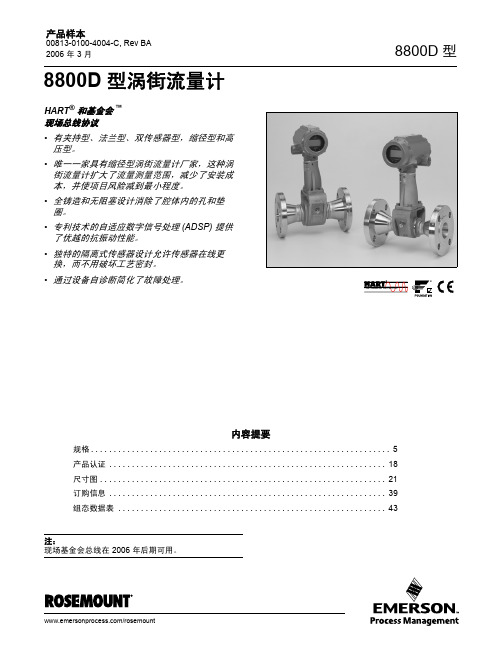
• 减少项目风险 - 缩径型涡街流量计和标准涡街 流量计有相同的法兰面对面尺寸。这样可以使 用任一种流量计而不影响管线布局。
• 缩径型涡街流量计为法兰型,从 1 到 12 英寸, 不锈钢和镍合金 C 材质。
• 具有基金会现场总线功能。
(1) 我们已经知道过程温度和管道内径 ID 会影响到 K 系数, 8800D 型软件通过补偿 K 系数来自动纠正这些影响。
4
产品样本
00813-0100-4004-C, Rev BA 2006 年 3 月
8800D 型
规格
下列规格适用于 8800D 型 , 8800DR 型和 8800DD 型,加注释的 除外。
自诊断
变送器自动进行连续的自诊断。用户能进行变送器数 字信号的在线测试,可用先进的仿真自诊断功能,通 过软件中流量信号发生器远程鉴定电子部件。传感器 信号强度可用来检查过程流量信号并提供滤波器设置 的相关信息。
产品样本
00813-0100-4004-C, Rev BA 2006 年 3 月
基金会现场总线功能块
• 全铸造和无阻塞设计消除了腔体内的孔和垫 圈。
• 专利技术的自适应数字信号处理 (ADSP) 提供 了优越的抗振动性能。
• 独特的隔离式传感器设计允许传感器在线更 换,而不用破坏工艺密封。
• 通过设备自诊断简化了故障处理。
8800D 型
内容提要
规格 . . . . . . . . . . . . . . . . . . . . . . . . . . . . . . . . . . . . . . . . . . . . . . . . . . . . . . . . . . . . . . . . . . 5 产品认证 . . . . . . . . . . . . . . . . . . . . . . . . . . . . . . . . . . . . . . . . . . . . . . . . . . . . . . . . . . . . . 18 尺寸图 . . . . . . . . . . . . . . . . . . . . . . . . . . . . . . . . . . . . . . . . . . . . . . . . . . . . . . . . . . . . . . . 21 订购信息 . . . . . . . . . . . . . . . . . . . . . . . . . . . . . . . . . . . . . . . . . . . . . . . . . . . . . . . . . . . . . 39 组态数据表 . . . . . . . . . . . . . . . . . . . . . . . . . . . . . . . . . . . . . . . . . . . . . . . . . . . . . . . . . . . 43
上海纳铁福传动轴有限公司长春分厂一期二期项目安全专篇-修改版
上海纳铁福传动轴有限公司长春分厂一期、二期建设项目安全专篇《修改版》吉林省机电研究设计院二〇一四年六月工程设计证书号:设甲级A122004851上海纳铁福传动轴有限公司长春分厂一期、二期建设项目安全专篇《修改版》吉林省机电研究设计院二〇一四年六月上海纳铁福传动轴有限公司长春分厂一期、二期建设项目安全专篇设计单位负责人院长:赵闾峰设计一所所长:张泳项目组人员目录附件附件1:企业营业执照附件2:《关于上海纳铁福传动轴有限公司长春分厂建设项目准予备案的通知》(长春汽车产业开发区管理委员会文件长汽开管经字[2010]2号)附件3:《关于上海纳铁福传动轴有限公司长春分厂建设项目环境影响报告书的批复》(长春市环境保护局汽车产业开发区分局长环汽开行审字[2010]2号)附件4:项目选址意见书附件5:建设工程规划许可证附表附表1:工艺设备一览表附表2:建设项目特种设备一览表附表3:建设项目主要安全设施明细表附图附图1:建设项目区域位置图附图2:项目总平面布置图附图3:生产厂房工艺区划图附图4:消防器材布局图附图5:涂装车间电气消防图1 设计依据1.1 法律、法规(1)《中华人民共和国安全生产法》(中华人民共和国主席令第70号,2002年11月1日起实施)(2)《中华人民共和国消防法》(中华人民共和国主席令第6号,2009年5月1日起实施)(3)《中华人民共和国劳动法》(中华人民共和国主席令第65号,2008年1月1日施行)(4)《中华人民共和国职业病防治法》(中华人民共和国主席令第60号,2002年5月1日施行)(5)《中华人民共和国防震减灾法》(中华人民共和国主席令第7号,2009 年5 月1 日起施行)(6)《中华人民共和国土地管理法》(中华人民共和国主席令第28号)(7)《特种作业人员安全技术培训考核管理规定》(国家安全生产监督管理总局令第30号)(8)《危险化学品安全管理条例》(国务院令第591号)(9)《特种设备安全监察条例》(国务院令第549号)(10)《机械建设项目初步设计安全专篇编写提纲》(安监总厅管四〔2011〕205号);(11)《作业场所职业健康监督管理暂行规定》[国家安监总局令(第23号)](12)《建设项目安全设施“三同时”监督管理暂行办法》(国家安监总局令36号)(13)《关于开展重大危险源监督管理工作的指导意见》(国家安全生产监督管理总局安监管协调字[2004]56号)(14)《固定式压力容器安全技术监察规程》(TSGR0004-2009)(中华人民共和国国家质量监督检验检疫总局颁布)(15)《国家重点监管的危险化学品名录》(2013年完整版)(16)《吉林省安全生产条例》(吉林省第十届人民代表大会常务委员会公告第35号,2005年6月1日起施行)(17)《关于加强作业场所职业卫生监管工作的通知》(吉安监管职卫字[2009]65号)(18)《关于加强作业场所职业危害检测检验工作的通知》吉安监管职卫字[2010]39号)(19)《危险化学品名录》(2002版)1.2 标准、规章及规范(1)《机械工业职业安全卫生设计规定》(JBJ18-2000)(2)《机械工业厂房建筑设计规范》(GB 50681-2011)(3)《工业企业总平面设计规范》(GB50187-2012)(4)《工业企业设计卫生标准》(GBZ1-2010)(5)《建筑设计防火规范》(GB50016-2006)(6)《建筑防雷设计规范》(GB50057-2010)(7)《建筑物抗震设计规范》(GB50011-2010)(8)《火灾自动报警系统设计规范》(GB50116-2013)(9)《建筑照明设计标准》(GB50034-2004)(10)《建筑给排水设计规范》(GB50015-2003)(2009年版)(11)《建筑内部装修设计防火规范》(GB50222-1995)(12)《建筑灭火器配置设计规范》(GB50140-2005)(13)《室内消火栓》(GB3445-2005)(14)《民用建筑供暖通风与空气调节设计规范》(GB 50736-2012)(15)《压缩空气站设计规范》(GB50029-2003)(16)《工业建筑防腐蚀设计规范》(GB50046-2008)(17)《低压配电设计规范》(GB50054-2011)(18)《供配电系统设计规范》(GB50052-2009)(19)《危险化学品重大危险源辨识》(GB 18218-2009)(20)《生产过程安全卫生要求总则》(GB12801-2008)(21)《职业性接触毒物危害程度分级》(GBZ230-2010)(22)《生产设备安全卫生设计总则》(GB5083-1999)(23)涂装作业安全规程(GB7691-2003)(24)《工作场所有害因素职业接触限值第1部分化学因素》(GBZ2.1-2007)(25)《工作场所有害因素职业接触限值第2部分物理因素》(GBZ2.2-2007)(26)《工业企业厂内铁路、道路运输安全规程》(GB4387-2008)(27)《消防安全标志设置要求》(GB15630-1995)(28)《生产经营单位安全生产事故应急预案编制导则》(GB/T 29639-2013)(29)《焊接与切割安全》(GB9448-1999)(30)《机械安全防护装置固定式和活动式防护装置设计与制造一般要求》(GB/T 8196-2003)(31)《机械安全指示、标志和操作》(GB18209-2000)(32)《金属切学削加工安全要求》(JB7741-1995)(33)《机械安全避免人体各部位挤压的最小间距》(GB12265.3-1997)(34)《防止静电事故通用导则》(GB12158-2006)(35)《危险货物包装标志》(GB190-2009)(36)《化学品分类和危险性公示通则》(GB13690-2009)(37)《安全标志及其使用导则》(GB2894-2008)(38)《安全色》((GB2893-2008)(39)《工业管路的基本识别色、识别符号和安全标识》(GB7231-2003)(40)《机动工业车辆安全规范》(GB/T10827-1999)(41)《易燃易爆性商品储藏养护技术条件》(GB17914-1999)(42)《常用危险化学品储存通则》(GB15603-1995)(43)《腐蚀性商品储藏养护技术条件》(GB 17915-1999)(44)《危险货物运输包装通用技术条件》(GB12463-2009)(45)《包装储运图示标志》(GB/T191-2008)(46)《危险货物分类和品名编号》(GB6944-2005)(47)《固定式钢梯及平台安全要求第1部分:钢直梯》(GB4053.1-2009)(48)《固定式钢梯及平台安全要求第2部分:钢斜梯》(GB4053.2-2009)(49)《固定式钢梯及平台安全要求第3部分:工业防护栏杆及钢平台》(GB4053.3-2009)1.3 其他相关依据(1)《上海纳铁福传动轴有限公司长春分厂建设项目可行性研究报告》(上海市机电设计研究院有限公司);(2)《上海纳铁福传动轴有限公司长春分厂等速万向节传动轴二期扩能技术改造项目可行性研究报告》(上海市机电设计研究院有限公司);(3)《关于上海纳铁福传动轴有限公司长春分厂建设项目准予备案的通知》(长春汽车产业开发区管理委员会文件长汽开管经字[2010]2号);(4)《上海纳铁福传动轴有限公司长春分厂一二期建设项目安全预评价报告》(吉林省平安安全技术咨询有限公司);(5)建设单位提供的有关基础资料;(6)现场调查收集的有关资料等;2 建设项目概述2.1 工程性质及设计内容2.1.1 工程性质新建项目。
- 1、下载文档前请自行甄别文档内容的完整性,平台不提供额外的编辑、内容补充、找答案等附加服务。
- 2、"仅部分预览"的文档,不可在线预览部分如存在完整性等问题,可反馈申请退款(可完整预览的文档不适用该条件!)。
- 3、如文档侵犯您的权益,请联系客服反馈,我们会尽快为您处理(人工客服工作时间:9:00-18:30)。
中等载荷8800系列电液伺服系统
中等载荷电液伺服试验系统可用于疲劳及静态试验.在材料和部件的测试方面载荷容量可高达500kN.根据不同的配置及使用的配件,这些系统可以执行低周和高周循环疲劳试验,裂纹扩展和断裂韧性测试以及其他测试。
也可提供对部件和结构进行理想测试的T型槽底座.每个系统都可以方便地配置适当大小的伺服阀,多种液压动力装置满足各种疲劳性能测试。
所有系统都配备了先进的8800数字控制器,Console软件,以及独特的具有惯性补偿功能的Dynacell™动态载荷传感器。
WaveMatrix™动态测试软件为动态测试运行提供了许多数据支撑。
其他应用程序具体的软件模块,如LCF3低循环疲劳或任何Instron的力学断裂软件模块,都允许其标准化测试运行。
当Bluehill®2软件和相应的配件相结合时,这些动态系统,也会是各种静态拉伸,压缩,弯曲,剥离,撕裂,摩擦等测试的理想选择。
中等载荷电液伺服系统包括:
8802电液伺服系统,作动缸载荷容量达到250kN
8803电液伺服系统,作动缸载荷容量250kN到500kN
8804四立柱电液伺服系统,作动缸载荷容量达到500kN
简介:8802大载荷疲劳试验机具有精准定位和高刚度机架,可从基本的金属至较大型的元件进行范围广泛的静态和动态试验应用。
这种伺服液压试验机通常用于断裂力学、钢筋、航天用板件、钢索、土木元件或结构、小型混凝土和岩石力学的检测。
动态测试系统具有双立柱机架,配有液压升降及锁定装置,可将作动缸置于工作台或上横梁。
此精密机械系统整合了先进的8800数字控制器和Dynacell™载荷传感器,英斯特朗可提供完整的统包方案,以满足各种应用需求。
由电脑通过操作台软件进行控制,包括波形生成、校准、设定限制和状态监控。
可加装WaveMatrix™模块化软件对材料或零件进行简易及进阶性循环测试,或使用Bluehill® 2软件进行静态测试。
功能特点:高达±250kN的轴向载荷容量;双立柱、高刚度及精准定位的机架;上横梁的液压升降及锁定装置;位于下工作台或上横梁的作动缸;可选择标准、特高或超高机架;专利DynaceII载荷传感器,可抵消夹具及工装造成的惯性载荷负载;各种夹具、工装及配件。
主要参数:
压板间距:标准1240mm(48.8in.),特高型1700mm(66.9in.),超高型2100mm(82.7in.)动态载荷容量:±250kN(±56kip)
作动器行程:150mm(5.9in.)
配置:作动缸安装于双立柱上端横梁中间以及T型槽底座
升降与锁紧装置:电液升降并有手动限位装置
加载称量精度:设定值的±5%或载荷传感器容量(1-100%)的0.005%,取较大值
载荷传感器:专利型Dynacell载荷传感器,可抵消夹具和工装造成的惯性负载
多管阀选项:单向阀、双向阀或高速流阀
伺服阀选项:5, 10, 20, 40, 65 or 230l/min (1, 2.5, 5, 10, 16.5 or 60GPM)
液压:207bar(3000psi)
电源:单相180-264V,45/65Hz,功率最大800VA
机架刚度:585kN/mm
机架质量:1330kg(2929lb)
操作环境:+10-38°C。
10%-90%湿度(非冷凝)
简介:8803大载荷疲劳试验机具有精准定位和高刚度机架,可从基本的金属至较大型的元件进行范围广泛的静态和动态试验应用。
这种伺服液压试验机通常用于断裂力学、钢筋、航天用板件、钢索、土木元件或结构、小型混凝土和岩石力学的检测。
动态测试系统具有双立柱机架,配有液压升降及锁定装置,可将作动缸置于工作台或上横梁。
此精密机械系统整合了先进的8800数字控制器和Dynacell™载荷传感器,英斯特朗可提供完整的统包方案,以满足各种应用需求。
由电脑通过操作台软件进行控制,包括波形生成、校准、设定限制和状态监控。
可加装WaveMatrix™模块化软件对材料或零件进行简易及进阶性循环测试,或使用Bluehill® 2软件进行静态测试。
功能特点:高达±500kN的轴向载荷容量;双立柱、高刚度及精准定位的机架;上横梁的液压升降及锁定装置;位于下工作台或上横梁的作动缸;可选择标准、特高或超高机架;专利DynaceII载荷传感器,可抵消夹具及工装造成的惯性载荷负载;各种夹具、工装及配件。
主要参数:
压板间距:标准1465mm(57.7n.),特高型1905mm(75.0in.),超高型2165mm(89.2in.)动态载荷容量:±500kN(±112kip)
作动器行程:250mm(9.8in.)
配置:作动缸安装于双立柱上端横梁中间以及T型槽底座
升降与锁紧装置:电液升降并有手动限位装置
加载称量精度:设定值的±5%或载荷传感器容量(1-100%)的0.005%,取较大值
载荷传感器:专利型Dynacell载荷传感器,可抵消夹具和工装造成的惯性负载
多管阀选项:单向阀、双向阀或高速流阀
伺服阀选项:5, 10, 20, 40, 65 or 230l/min (1, 2.5, 5, 10, 16.5 or 60GPM)
液压:207bar(3000psi)
电源:单相180-264V,45/65Hz,功率最大800VA
机架刚度:1066kN/mm
机架质量:2450kg(5396lb)
操作环境:+10-38°C。
10%-90%湿度(非冷凝)
8804伺服液压疲劳测试系统是一个带四立柱,载荷容量高达500kN的测试系统,具有精准定位和高刚度机架,配有液压升降及锁定装置,可将作动缸置于工作台或上横梁。
该精密机械系统整合了先进的8800数字控制器和DynaceII载荷传感器。
我公司可提供完整的统包方案以满足各种应用需求。
这种伺服液压试验机通常用于航天用板件、钢索、土木元件或结构、小型混凝土和岩石力学的检测。
有电脑通过操作软件进行控制,包括波形生成、校准、设定限制和状态监控。
可加装WaveMatrix模块化软件对材料或零件进行简易及进阶性循环测试,或使用Bluehill2软件进行静态测试。
主要参数:
压板间距:定制
动态载荷容量:±500kN(±112 500lbf)
作动器行程:定制
配置:作四立柱,高精度机架及高刚度材料
升降与锁紧装置:位于横梁上的电液升降并有手动限位装置
加载称量精度:设定值的±5%或载荷传感器容量(1-100%)的0.005%,取较大值
载荷传感器:专利型Dynacell载荷传感器,安装于横梁上端,可抵消夹具和工装造成的惯性负载
多管阀选项:单向阀、双向阀或高速流阀
伺服阀选项:5, 10, 20, 40, 65 or 230l/min (1, 2.5, 5, 10, 16.5 or 60GPM)
液压:207bar(3000psi)
电源:单相180-264V,45/65Hz,功率最大800VA
机架刚度:定制
机架质量:待定
操作环境:+10-38°C。
10%-90%湿度(非冷凝)
8861/8862高精度电动作动系统
简介:8861 和8862 配备单丝杆电动机械作动缸,以进行低速的静态试验,缓慢应变率及准动态循环试验。
该系统具有的高刚度,精确对中,双立柱载荷机架为无与伦比的测试表现提供了保障。
良好的试验空间调节, 方便进行各种测试, 为提高设备使用性, 8862 具备作动器上置或下置选项, 并添加了液压横梁升降调节。
结合 8800 数字控制器的技术优势和先进的英斯特朗自制疲劳载荷传感器技术8860系列在低周疲劳试验,热机械疲劳试验,高温静态试验,蠕变疲劳,缓慢应变率,陶瓷测试中都是理想的设备选择。
Console 软件通过PC 提供控制整个系统的操作,包括波形生成,标定,限位设置和测试监测。
加装 WaveMatrix™模块化软件后用户可以对部件或材料进行简易或复杂的试验;通过 Bluehill® 软件则可以进行静态试验,LCF3软件则可以执行高温环境下的低周疲劳试验。
功能特点
集成化8800数字控制系统
高精度的载荷传感器
作动缸导向系统保证了真正的无偏离轴向运动
测试速度可以小到1微米/小时
高精度的波形控制
低噪音
各种系统选项、夹具、工装和附件
载荷容量可达100kN。