1安全指南2设备结构-Jung
JR Clancy 剧场设备维护与安全指南说明书

Rigging InspectionGENERAL DESCRIPTIONPreventative maintenance and safety is an on going task, which involves full knowledge of the stage rigging equipment and its capabilities. Your knowledge should include the following:A. Know the feel, sound and smell of your equipment so that you will know when something is not right.B. Know the capacities and capabilities of the system and its components.C. Practice proper operating procedures.D. Know the people who operate your system and their abilities.E. Make periodic safety inspections.F. Ask the following questions each time a set is operated.1. Is the set balanced?2. Is the rope lock properly adjusted?3. Is there excessive friction in the system? Is it too hard to operate?4. Are the spreader plates properly spaced among the Counterweights and are the stop collarsdown on the top weight and locked?5. Are there any obstructions or fouled lines?INSPECTIONTime, temperature, humidity and both the frequency and severity of operation affect rigging items.A schedule should be established and followed for checking all items. The frequency with which inspections should be done depends upon the above parameters and will be unique to your program and location. Your inspection should at least include the items on the checklist, which is included at the end of this article.When heavy or complicated equipment exists we suggest that, in addition to your own periodic inspection, you hire a qualified stage rigging firm to do a full evaluation of your facility on a regular basis. We further suggest that you maintain full records of all inspections and maintenance for government (OSHA) and insurance purposes. Maintenance records are also useful in making future checks and in evaluating the potential useful life of equipment.INSPECTION CHECK LISTCreate an inspection checklist, which works for you and includes items that are unique to your facility and the uses to which it is put. The following list of potential items and questions is only intended as a guide to get you started in creating your own inspection list.A. GENERAL1. Fire Extinguishers?2. Scenerya. Properly stored and braced?b. Flame retarded?3. Curtainsa. Flame retardant up to dateb. Certificates on file?c. Holes, tears, burns?4. Tracksa. Securely fastened?b. Ropes in good shape?c. Carriers obstructed?d. End stops and pulleys tight?B. HEMP RIGGING1. Ropesa. Abrasion?b. Kinking?c. Over stressed?d. Rot or dry rot?e. Connections?DO NOT KEEP BAD ROPE. SOMEONE MAY MISTAKENLY USE IT.2. Head and Loft Blocksa. Mountings tight and undamaged?b. Bearings and shafts?c. Sheaves?3. Pin rail and its mounting?4. Belaying pins, sandbags, trim clamps?C. COUNTERWEIGHT RIGGING1. Lead Linesa. Abrasion, rust, broken strands, kinks?b. Terminations tight, properly applied, worn, cracked?c. Turnbuckles adjusted and safety wired?2. Hand Lines (See Hemp Rigging)3. Locking Raila. Undamaged?b. Properly and securely mounted?c. Index cards in place and correct?4. Rope Locksa. Properly adjusted?b. Condition?c. Wear on handles and dogs?d. Safety rings in place?5. Head, Loft and Mule Blocksa. Mounting?b. Bearings and shafts?c. Sheaves?6. Tension Sheave (See above)7. Counterweight Arbora. Top and bottom?b. Rods and nuts?c. Spreader plates and lock collars?LOCATE A SPREADER PLATE EVERY 3 FEET (1 m) AND KEEP STOP COLLARS DOWN AND LOCKED.d. Arbor guides?D. T-GUIDES AND LATTICE TRACKS1. Clean?2. Straight? Joints match up?E. FIRE CURTAIN SYSTEM1. All of the above?2. Smooth operation within prescribed time?3. Condition of curtain and guides?4. Fusible links?5. Release mechanism(s)?6. Obstructions to prevent free operation?7. Dashpot? Proper time of operation?8. Brail Winch? Handle stored?9. Motorized head block? Clutch operation?F. MOTORIZED RIGGING1. Rigging Components (See above)2. Controls? Emergency Stop?3. Motor?4. Gear Box?5. Limit Switches?6. Motor Starters?7. Motor and/or Load Brake?8. Drums, sprockets and chains?9. Couplings?10. Guards? Are they in Place?SUGGESTED INSPECTION FREQUENCYEQUIPMENT TYPE CLASS OF DUTYHEAVY MODERATE LIGHT(Daily Use) (Weekly Use) (Monthly Use) Rope & Cable Blocks Annual Annual Bi-annual Arbors and Shoes Annual Annual Bi-annual Cables and Fittings Annual Annual Bi-annualHand Lines Quarterly Semi-annual Semi-annual Rope Locks Quarterly Semi-annual Semi-annual Gear Boxes Annual Annual AnnualPillow and Flange Bearings Semi-annual Semi-annual Semi-annual Limit Switches Semi-annual Annual Annual Starters Semi-annual Annual Bi-annual NOTES: Actual frequency of inspection and maintenance should be determined from experience based upon evaluation of the operating environment, loading conditions, and frequency of use.TABLE 1The following example is a typical example of an inspection form:YOUR FACILITY RIGGING INSPECTIONREPORT Date _____________ Page of ___ Inspector_______________________________________ Assistant/Supervisor _________________System Type Counterweight Set Inspection Method: Visual ____System No. ___ Description______________________________________Disassembly ____Other ____PRODUCT DESCRIPTION CK’D. COMMENTSHead BlockLoft Block - Short LineLoft Block - Short CenterLoft Block - CenterLoft Block - Long CenterLoft Block - Long LineCounterweight ArborFloor BlockRope LockHand LineCablesAttachments @ ArborAttachments @ BattenBattenNOTES:.。
安全阀结构及其工作原理
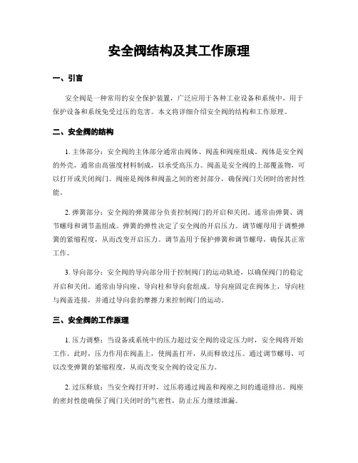
安全阀结构及其工作原理一、引言安全阀是一种常用的安全保护装置,广泛应用于各种工业设备和系统中,用于保护设备和系统免受过压的危害。
本文将详细介绍安全阀的结构和工作原理。
二、安全阀的结构1. 主体部分:安全阀的主体部分通常由阀体、阀盖和阀座组成。
阀体是安全阀的外壳,通常由高强度材料制成,以承受高压力。
阀盖是安全阀的上部覆盖物,可以打开或关闭阀门。
阀座是阀体和阀盖之间的密封部分,确保阀门关闭时的密封性能。
2. 弹簧部分:安全阀的弹簧部分负责控制阀门的开启和关闭。
通常由弹簧、调节螺母和调节盖组成。
弹簧的弹性决定了安全阀的开启压力。
调节螺母用于调整弹簧的紧缩程度,从而改变开启压力。
调节盖用于保护弹簧和调节螺母,确保其正常工作。
3. 导向部分:安全阀的导向部分用于控制阀门的运动轨迹,以确保阀门的稳定开启和关闭。
通常由导向座、导向柱和导向套组成。
导向座固定在阀体上,导向柱与阀盖连接,并通过导向套的摩擦力来控制阀门的运动。
三、安全阀的工作原理1. 压力调整:当设备或系统中的压力超过安全阀的设定压力时,安全阀将开始工作。
此时,压力作用在阀盖上,使阀盖打开,从而释放过压。
通过调节螺母,可以改变弹簧的紧缩程度,从而改变安全阀的设定压力。
2. 过压释放:当安全阀打开时,过压将通过阀盖和阀座之间的通道排出。
阀座的密封性能确保了阀门关闭时的气密性,防止压力继续泄漏。
3. 过压恢复:一旦过压释放后,设备或系统的压力将逐渐下降。
当压力降低到安全阀设定压力以下时,弹簧将推动阀盖关闭阀门,停止过压释放。
四、安全阀的应用安全阀广泛应用于各种工业设备和系统中,如锅炉、压力容器、管道系统等。
其作用是保护设备和系统免受过压的危害,防止设备破裂或系统失效。
五、结论安全阀是一种重要的安全保护装置,其结构和工作原理决定了其可靠性和稳定性。
了解安全阀的结构和工作原理对于正确选择、安装和维护安全阀至关重要。
通过合理设置安全阀的设定压力,可以有效保护设备和系统的安全运行。
安全阀结构原理
安全阀结构原理
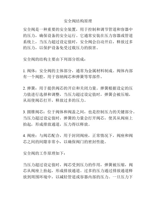
安全阀是一种重要的安全装置,用于控制和调节管道和容器中的压力,确保设备的安全运行。
它通常安装在压力容器或管道系统上,当压力超过设定值时,安全阀会自动开启,释放过多的压力,以保护设备免受过载压力的损害。
安全阀的结构主要由下列部分组成:
1. 阀体:安全阀的主体部分,通常为金属材料制成。
阀体内部有一个阀腔,用于容纳阀芯和弹簧等零部件。
2. 弹簧:用于提供阀芯的开启和关闭力量。
弹簧根据设定的压力值进行选择和调整,当压力超过设定值时,弹簧会被压缩,从而使阀芯打开,释放过多的压力。
3. 圆锥阀芯:位于阀体和阀盖之间,也是控制压力的关键部分。
当压力超过设定值时,弹簧的力量会打开阀芯,使其从阀座上抬起,形成排放通道,压力得以释放。
4. 阀座:与阀芯配合,用于封闭阀座,正常情况下,阀座和阀芯之间的间隙非常小,以确保阀门的密封性能。
安全阀的工作原理如下:
当压力超过设定值时,阀芯受到压力的作用,弹簧被压缩,阀芯从阀座上抬起,形成排放通道。
过多的压力通过排放通道释放到周围环境中,以减轻管道或容器内部的压力。
一旦压力下
降到设定值以下,弹簧会推动阀芯回到原位,阀门关闭,停止排放。
通过上述结构和工作原理,安全阀能够持续监测和控制压力,确保系统处于安全的压力范围内,防止过载压力对设备和人员造成损害。
因此,在各类工业设备和管道系统中广泛使用安全阀来保护设备和人员的安全。
安全阀结构及其工作原理
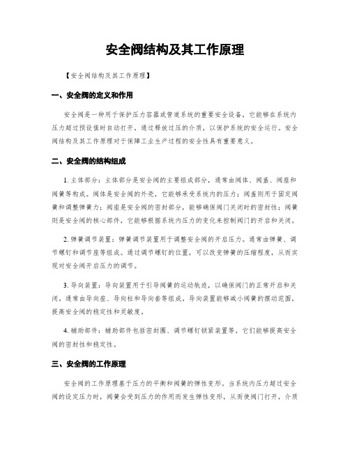
安全阀结构及其工作原理【安全阀结构及其工作原理】一、安全阀的定义和作用安全阀是一种用于保护压力容器或管道系统的重要安全设备,它能够在系统内压力超过预设值时自动打开,通过释放过压的介质,以保护系统的安全运行。
安全阀结构及其工作原理对于保障工业生产过程的安全性具有重要意义。
二、安全阀的结构组成1. 主体部分:主体部分是安全阀的主要组成部分,通常由阀体、阀盖、阀座和阀簧等构成。
阀体是安全阀的外壳,它能够承受系统内的压力;阀盖则用于固定阀簧和调整弹簧力;阀座是安全阀的密封部分,能够确保阀门关闭时的密封性;阀簧则是安全阀的核心部件,它能够根据系统内压力的变化来控制阀门的开启和关闭。
2. 弹簧调节装置:弹簧调节装置用于调整安全阀的开启压力。
通常由弹簧、调节螺钉和调节座等组成。
通过调节螺钉的位置,可以改变弹簧的压缩程度,从而实现对安全阀开启压力的调节。
3. 导向装置:导向装置用于引导阀簧的运动轨迹,以确保阀门的正常开启和关闭。
通常由导向座、导向柱和导向套等组成。
导向装置能够减小阀簧的摆动范围,提高安全阀的稳定性和灵敏度。
4. 辅助部件:辅助部件包括密封圈、调节螺钉锁紧装置等,它们能够提高安全阀的密封性和稳定性。
三、安全阀的工作原理安全阀的工作原理基于压力的平衡和阀簧的弹性变形。
当系统内压力超过安全阀的设定压力时,阀簧会受到压力的作用而发生弹性变形,从而使阀门打开,介质通过阀门释放到外部,以降低系统压力。
当系统压力恢复到设定压力以下时,阀簧会恢复原状,阀门关闭,保持系统正常工作。
四、安全阀的工作特点1. 灵敏性:安全阀对压力变化非常敏感,能够在短时间内做出反应,快速打开或关闭阀门,确保系统的安全性。
2. 稳定性:安全阀能够在设定压力范围内稳定工作,不会因外界因素的影响而产生误动作或漏气现象。
3. 可靠性:安全阀经过严格的设计和制造,具有较高的可靠性和耐久性,能够长时间稳定运行。
4. 自动性:安全阀能够根据系统内压力的变化自动开启或关闭,不需要人工干预,提高了工作效率和安全性。
安全阀结构及其工作原理
安全阀结构及其工作原理安全阀是一种常见的安全装置,广泛应用于各种工业设备和系统中,用于保护设备和系统免受过压的危害。
安全阀的结构和工作原理是保证其正常运行和可靠性的关键因素。
一、安全阀的结构1. 主体部分:安全阀的主体部分通常由阀体、阀盖和阀座组成。
阀体是安全阀的主要承压部件,一般采用高强度的铸铁或钢材料制造,具有良好的耐压性能。
阀盖用于固定阀簧和调整弹簧力的大小。
阀座是安全阀的密封部件,通常采用耐磨损、耐高温的合金材料制成。
2. 弹簧装置:安全阀的弹簧装置用于控制阀簧的开启和关闭。
弹簧通常采用高强度的合金钢材料制造,具有一定的弹性和稳定性。
弹簧的刚度决定了安全阀的开启压力和关闭压力。
3. 导向装置:安全阀的导向装置用于确保阀簧在工作过程中的稳定性和准确性。
导向装置通常由导向套、导向销和导向垫片等部件组成。
4. 调整装置:安全阀的调整装置用于调整阀簧的预压力和开启压力。
调整装置通常由调整螺母、调整垫片和调整螺栓等部件组成。
二、安全阀的工作原理安全阀的工作原理基于力的平衡原理。
当设备或系统内部压力超过设定的安全阀开启压力时,安全阀将自动开启,释放过多的压力,以保护设备和系统的安全。
1. 预压力调整:通过调整装置调整安全阀的预压力,即阀簧的初始压力。
预压力决定了安全阀的关闭状态下所能承受的最大压力。
2. 开启压力调整:通过调整装置调整安全阀的开启压力,即阀簧的压力达到一定数值时,安全阀开始开启。
开启压力决定了安全阀在超压情况下的响应速度和释放压力的大小。
3. 压力平衡:当设备或系统内部压力超过安全阀的开启压力时,阀簧受到压力的作用,逐渐压缩,直到阀簧的压力达到开启压力。
此时,安全阀开始开启,将多余的压力释放出去,以保持设备或系统内部压力在安全范围内。
4. 关闭状态:当设备或系统内部压力恢复到安全范围内时,阀簧的压力减小,安全阀逐渐关闭,恢复到关闭状态。
安全阀的关闭状态下所能承受的最大压力由预压力决定。
安全阀结构及其工作原理
安全阀结构及其工作原理引言概述:安全阀是一种常见的防护装置,广泛应用于各种工业设备和系统中。
它的主要作用是在设备或者系统内部压力超过安全范围时,通过释放压力来保护设备和人员的安全。
本文将详细介绍安全阀的结构及其工作原理。
一、安全阀的结构1.1 弹簧:安全阀的弹簧是其中一个重要组成部份,它负责控制阀门的开启和关闭。
弹簧的弹性决定了阀门的开启压力和关闭压力。
普通情况下,弹簧采用高强度合金材料制成,以确保其在高压环境下的稳定性和可靠性。
1.2 阀盖:阀盖是安全阀的外部保护壳,它起到密封和固定弹簧的作用。
阀盖通常采用铸铁或者钢材料制成,以确保其足够的强度和耐腐蚀性。
1.3 阀座:阀座是安全阀的内部密封部件,它与阀盖密切配合,起到密封阀门的作用。
阀座通常采用耐高温和耐腐蚀的合金材料制成,以确保其在高压和高温环境下的可靠性。
二、安全阀的工作原理2.1 开启压力设定:安全阀的开启压力是通过调整弹簧的预紧力来设定的。
当设备或者系统内部压力超过设定的开启压力时,弹簧将被压缩到一定程度,阀门将自动打开,释放压力。
2.2 关闭压力设定:安全阀的关闭压力是通过调整弹簧的松弛力来设定的。
当设备或者系统内部压力降低到设定的关闭压力以下时,弹簧将恢复原状,阀门将自动关闭,住手释放压力。
2.3 快速响应:安全阀在压力超过设定值时能够迅速响应,打开阀门释放压力,以确保设备和人员的安全。
它的快速响应是通过弹簧的设计和材料选择来实现的。
三、安全阀的应用领域3.1 锅炉系统:安全阀在锅炉系统中起到了关键的作用,它能够在锅炉内部压力超过设定值时及时释放压力,保护锅炉的安全运行。
3.2 石油化工设备:石油化工设备通常在高温高压环境下工作,安全阀能够确保设备在超过安全范围时及时释放压力,防止设备损坏或者事故发生。
3.3 气体储存系统:安全阀在气体储存系统中起到了重要的作用,它能够在气体压力超过设定值时释放压力,防止储存罐爆炸或者泄漏。
四、安全阀的维护和检修4.1 定期检查:安全阀需要定期检查,包括检查弹簧的弹性和阀盖的密封性能等。
安全指南与使用指南:安全应用、安装和维护实体状态控制系统
Block I/OCat. No. 1791-IOBA and -IOBB User Manual© 1991 Allen-Bradley Company, Inc.PLC is a registered trademark of Allen-Bradley Company, Inc.SLC is a registered trademark of Allen-Bradley Company, Inc.Because of the variety of uses for this product and because of thedifferences between solid state products and electromechanical products,those responsible for applying and using this product must satisfythemselves as to the acceptability of each application and use of this product. For more information, refer to publication SGI–1.1 (Safety Guidelines For The Application, Installation and Maintenance of Solid State Control).The illustrations, charts, and layout examples shown in this manual are intended solely to illustrate the text of this manual. Because of the many variables and requirements associated with any particular installation,Allen–Bradley Company cannot assume responsibility or liability for actual use based upon the illustrative uses and applications.No patent liability is assumed by Allen–Bradley Company with respect to use of information, circuits, equipment or software described in this text.Reproduction of the contents of this manual, in whole or in part, without written permission of the Allen–Bradley Company is prohibited.Throughout this manual we make notes to alert you to possible injury to people or damage to equipment under specific circumstances.WARNING: Tells readers where people may be hurt if procedures are not followed properly.CAUTION: Tells readers where machinery may be damagedor economic loss can occur if procedures are not followed properly.Warnings and Cautions:-Identify a possible trouble spot.-Tell what causes the trouble.-Give the result of improper action.-Tell the reader how to avoid trouble.Important: We recommend you frequently backup your application programs on appropriate storage medium to avoid possible data loss.Important User InformationS-1Summary of ChangesThis issue of the manual contains new information and updatedinformation.New InformationThis version of the manual includes the addition of the 1791–IOBB block I/O module.The 1791–IOBB block I/O module has:10 inputs6 outputsUpdated InformationThis manual also includes the addition of information previously included in publication 1791–6.5.1–DU1, the documentation update which covered the 1791–IOBB block I/O module. This manual also includes revised specifications for both the –IOBA and –IOBB.To help you find new and updated information in this manual, we have included change bars as shown to the right of this paragraph.Summary of ChangesTable of Contents Important User Information I. . . . . . . . . . . . . . . . . . . . . . . .. . . . . . . . . . . . . . . . . . . . . . . . . . . . Summary of Changes S-1. . . . . . . . . . . . . . . . . . . . . . . . . . . . . . . Using This Manual 1Ć1 Purpose of Manual 1Ć1. . . . . . . . . . . . . . . . . . . . . . . . . . . . . . . . . . . Audience 1Ć1 . . . . . . . . . . . . . . . . . . . . . . . . . . . . . . . . . . . . . . . . . .. . . . . . . . . . . . . . . . . . . . . . . . . . . . . . . . . . . . . . . . Vocabulary 1Ć1 Manual Organization 1Ć1. . . . . . . . . . . . . . . . . . . . . . . . . . . . . . . . . Warnings and Cautions 1Ć2. . . . . . . . . . . . . . . . . . . . . . . . . . . . . Related Publications 1Ć2. . . . . . . . . . . . . . . . . . . . . . . . . . . . . . . . Introducing Block I/O 2Ć1. . . . . . . . . . . . . . . . . . . . . . . . . . . . .. . . . . . . . . . . . . . . . . . . . . . . . . . . . . . . . . . . Chapter Objectives 2Ć1. . . . . . . . . . . . . . . . . . . . . . . . . . . . . . . . . . General Description 2Ć1 How Block I/O Fits in a PLC System 2Ć2. . . . . . . . . . . . . . . . . . . . . . . Summary 2Ć4 . . . . . . . . . . . . . . . . . . . . . . . . . . . . . . . . . . . . . . . . .. . . . . . . . . . . . . . . . . . . . . . . . . . . . . . . Installing Block I/O 3Ć1. . . . . . . . . . . . . . . . . . . . . . . . . . . . . . . . . . . Chapter Objectives 3Ć1 Pre-installation Considerations 3Ć1. . . . . . . . . . . . . . . . . . . . . . . . . .. . . . . . . . . . . . . . . . . . . . . . . . . . . . . . . . Installing the Block I/O 3Ć2 Connecting Wiring 3Ć3. . . . . . . . . . . . . . . . . . . . . . . . . . . . . . . . . . . Remote I/O Link or Distributed I/O Link Wiring 3Ć6. . . . . . . . . . . . . . . Extended Node Capability 3Ć8. . . . . . . . . . . . . . . . . . . . . . . . . . . . . . Compatibility of 1771 I/O Products with Extended Node Numbers 3Ć9. . Summary 3Ć9 . . . . . . . . . . . . . . . . . . . . . . . . . . . . . . . . . . . . . . . . .Configuring Y our Block I/O for PLCFamily Programmable Controllers 4Ć1. . . . . . . . . . . . . . . Chapter Objectives 4Ć1. . . . . . . . . . . . . . . . . . . . . . . . . . . . . . . . . . . Setting the Configuration Switches 4Ć1. . . . . . . . . . . . . . . . . . . . . . . . Summary 4Ć6 . . . . . . . . . . . . . . . . . . . . . . . . . . . . . . . . . . . . . . . . .Table of Contentsii. . . . . . . . .Configuring Y our Block I/O for SLC Controllers 5Ć1. . . . . . . . . . . . . . . . . . . . . . . . . . . . . . . . . . .Chapter Objectives 5Ć1Setting the Configuration Switches 5Ć1. . . . . . . . . . . . . . . . . . . . . . . .Addressing the Blocks Using SLC Controllers 5Ć3. . . . . . . . . . . . . . . .Summary 5Ć3. . . . . . . . . . . . . . . . . . . . . . . . . . . . . . . . . . . . . . . . .. . . . . . . . . . . . . . . . . . . . . . . . . . . . . . . .Troubleshooting 6Ć1. . . . . . . . . . . . . . . . . . . . . . . . . . . . . . . . . . .Chapter Objectives 6Ć1LED Indicators 6Ć1. . . . . . . . . . . . . . . . . . . . . . . . . . . . . . . . . . . . . .. . . . . . . . . . . . . . . . . . . . . . . . . . . . . . . . . . . . . . . . .Summary 6Ć2. . . . . . . . . . . . . . . . . . . . . . . . . . . . . . . . . .Specifications AĆ11Ć1Using This ManualThis manual shows you how to use your Block I/O with an Allen–Bradley programmable controller. It helps you install, program and troubleshoot your module.You must be able to program and operate an Allen–Bradley programmable controller (PLC) to make efficient use of Block I/O modules.We assume that you know how to do this in this manual. If you do not,refer to the appropriate PLC programming and operations manual before you attempt to program this module.In this manual, we refer to: the block I/O module as the “block” or the “module” the programmable controller as the “controller”This manual is divided into 6 chapters. The following chart shows eachchapter with its corresponding title and brief overview of the topics covered in that chapter.Purpose of ManualAudienceVocabularyManual Organization1Ć2This manual may contain warnings and cautions. A warning tells where you may be injured if you use your equipment improperly. Cautions tell where equipment may be damaged from misuse.You should read and understand cautions and warnings before performing the procedures they precede.For a list of publications with information on Allen–Bradley programmable controller products, consult our publication index (SD499).Warnings and Cautions Related Publications2Ć1Introducing Block I/OIn this chapter you will learn what block I/O is, and its features, and how it functions.Block I/O consists of small, self–contained remote I/O devices completewith power supply, programmable controller interface, input/output connections and signal conditioning circuitry.Two types of block I/O are available. The 1791–IOBA has 8 inputs and 8outputs; the 1791–IOBB has 10 inputs and 6 outputs. In all other aspects,they are identical.The blocks are compatible with PLC–2, PLC–3, and PLC–5 family programmable controllers, and the SLC 500 modular controllers. When used with PLC–2 family programmable controllers, a sub I/O scanner module (cat. no. 1771–SN) or remote I/O scanner module (cat. no.1772–SD2) is used to communicate with the blocks. When used with PLC–3 and PLC–5 family programmable controllers, they can beconnected directly to the controller, a scanner module, or through a remote I/O adapter module. When used with SLC 500 controllers, a 1747–DSN scanner (or the 1747–SN Remote I/O scanner) is used to communicate with the blocks.Physical features of the block I/O are shown in Figure 2.1.Figure 2.1Major Features of the Block I/O Module (1791-IOBA shown)Removable Remote I/O Link Connector Removable Input/Output Connector 10825-IChapter ObjectivesGeneral Description2Ć2Wiring Connectors – The remote I/O link connector and input/output connector are removable for easy connection of wiring.Switch Assemblies – Two DIP switches are provided for setting the I/O rack number, starting I/O group, transmission rate, last chassis, last state and DH–485 terminator.Status Indicators – LED indicators are provided for communication, power and input/output status. These provide a visual indication for aid in troubleshooting.DH–485 Port – A plug–in port is provided for use with DH–485 data link when used with the SLC controller.Block I/O is a complete I/O interface that includes the functionality of the I/O rack, adapter, power supply, and I/O modules in a single unit. Simply connect sensors and actuators to the module and use the remote I/O cable to connect the block I/O to your programmable controller (Figure 2.4).The block uses sinking inputs and sourcing outputs.In sinking inputs(Figure 2.2), the dc common is bussed on the block. and the current is sourced from the field device. The sourcing field device switches the hot side of the power supply bus causing current to flow through the sourcing device to the sinking input on the block.Figure 2.2Sinking Input Example+V10826-ISourcing outputs(Figure 2.3) have the power bussed in the block. When the output is on, current is supplied to the field control device, which sinks the current. The field circuit and the equipment remain at ground potential until the output is turned on.How Block I/O Fits in a PLC System2Ć3Figure 2.3Sourcing Output ExampleYou connect the block I/O to your remote I/O link as you would any other device (Figure 2.4). The block looks like a 1/4 I/O rack to the processor,and uses 2 words of input image table memory and 2 words of outputimage table memory. The block is addressed directly on the remote I/O link.Block I/O functions exactly like any Allen–Bradley remote I/O product.Input and output data is scanned asynchronously and transferred back and forth between the block and the controller input and output image table.Figure 2.4Block I/O Connection in a PLC Systemor Scanner .SummaryIn this chapter you learned what block I/O is, its features and how itfunctions.Installing Block I/OIn this chapter you will learn how to mount the block, connect the remote I/O link, connect the input and output wiring to the block, and terminate the remote I/O link.Before installation, you must determine: the number of blocks desiredthe total distance of the installation transmission rate desiredif external fuses are requiredRefer to Table 3.A for acceptable combinations.Table 3.AAcceptable Combinations of Processor and Block I/OChapter ObjectivesPre-installation Considerationsisolated couplers). The maximum DH-485 network distance is 4,000 cable-feet.Mounting dimensions for the block I/O module are shown in Figure 3.1.Mount the blocks horizontally with a minimum of 2” between blocks. This air gap is necessary to maintain proper cooling air flow through the block.Figure 3.1Mounting Dimensions for the Block I/O Module (Cat. No. 1791-IOBA and -IOBB)10mm 10mm 0.39"Depth = 84.33mm (3.32")The operating temperature in the air gap between block I/O modules must not exceed 55o C (151o F). The dimensions of the air gap required are shown in Figure 3.2.Installing the Block I/OFigure 3.2Clearance Required for Block I/O ModulesConnections to the block I/O module are made to the removableconnectors which plug into the front of the block. The connector blocks are keyed to prevent incorrect insertion.Wiring for the block is shown in Figure 3.3 and Figure 3.4. Remote I/O link wiring connections are shown in Figure 3.5.Figure 3.3Input and Output Connections for the 1791-IOBA+24DCN CG VDC O0O1O2O3O4O5 I0 I1I2 I3I4 I5I6 I7COMNC 8 OUTPUTS 8 INPUTSINPUT 7INPUT 6INPUT 5INPUT 4INPUT 3INPUT 2OUTPUT 0OUTPUT 1OUTPUT 2OUTPUT 3OUTPUT 4OUTPUT 5INPUT 1INPUT 0+24V dc dc Neutral Output +Vdc Chassis GroundInput CommonO6O7OUTPUT 6OUTPUT 72SHD B A COM1Remote I/O Link (see Figure 3.5)DH-485(for SLC only)1791-IOBA - 8 inputs and 8 outputs10831-IConnecting W iringFigure 3.4Input/Output W iring Connections for the 1791-IOBB+24DCN CGVDC O0O1O2O3O4O5I0I1I2I3I4I5I6I7I8I9COMNC 6 OUTPUTS10 INPUTS INPUT 9INPUT 8INPUT 7INPUT 6INPUT 5INPUT 4OUTPUT 0OUTPUT 1OUTPUT 2OUTPUT 3OUTPUT 4OUTPUT 5INPUT 3INPUT 2INPUT 1INPUT 0+24V dc dc Neutral Output +Vdc Chassis Ground Input Common2SHD B A COM1Remote I/O LinkDH-485(for SLC only)Table 3.BWiring Block DesignationsPower Supply RequirementsAn external 24V dc power supply is required to power the block. Total current required to power the block is equal to 200mA plus an inrush of 5.5A for 10µsec for each block. The supply must be able to source an additional 100mA plus an inrush current of 400mA when a peripheral is connected.In addition, the external power supply should have current limiting capabilities. The voltage range must not exceed 20.5–27.6V dc.Wiring RequirementsWiring cable requirements are shown in the following table.Table 3.CAcceptable W iring Cables for Block I/O ConnectionFigure 3.5Remote I/O Link W iring 10832-IBlocks must be wired in series as shown in Figure 3.6 or Figure 3.7. Do not attempt to wire any block in parallel.The number of blocks used depends not only on the user requirements but also on the system used. Refer to Table 3.A for maximum block usage for individual systems.Figure 3.6Series Connection for Block I/O Using PLC-2, PLC-3 or PLC-5 Family Programmable ControllersTo Programmable Controller or I/O Scanner Module1 I/O Rack1 I/O Rack1 I/O Rack1 I/O Rack10833-IRemote I/O Link orDistributed I/O Link WiringFigure 3.7Series Configurations for Block I/O Using the SLC ProgrammableControllerTo 1747-DSNUp to 30 blocks withSLC-5/02toron last block.10834-ITermination ResistorA termination resistor must be installed on the last block in the series.Connect the resistor as shown in Figure 3.8. Use the resistor as identified in Table 3.D.Figure 3.8Installing the T ermination Resistorand 210835-ITable 3.DTerminator RequirementsIf this is the last remote I/O adapter on the remote I/O link in a PLC system, you must use a terminating resistor to terminate both ends of the remote I/O link (scanner end and last block end). The size of the terminator is determined by the system configuration.Older configurations can use a 150 ohm resistor at both ends. With newer devices that can support it, you can use an 82 ohm termination resistor at both ends. The 82 ohm terminators provide ”extended node” capability which allows you to have up to 32 physical devices on the remote I/O link.(The number of logical racks capable of being addressed by the scanner is not affected.)CAUTION: Devices that are operating at 230.4K baud must have 82 ohm terminators in place for proper operation.Extended Node CapabilityCertain products are not compatible with extended node capabilities obtained with the use of 82 ohm terminators. The following table lists those products that are not compatible.In this chapter you learned how to physically mount your block I/O, make power wiring connections, make the input/output wiring connections to the block, and terminate the remote I/O link.Compatibility of 1771 I/O Products with Extended Node NumbersSummary4Ć1Configuring Your Block I/O for PLC Family Programmable ControllersIn this chapter you will learn how to configure your block I/O when used with PLC family programmable controllers. This includes the following: setting the configuration switches addressing the block I/OEach block I/O module has two 6–position DIP switches for setting: starting I/O group I/O rack number transmission (baud) rate last chassis last stateDH–485 terminatorThese switches are accessible by opening the door on the left side of the module (Figure 4.1).Chapter ObjectivesSetting the Configuration Switches4Ć2Figure 4.1 Switch SettingsTable 4.AI/O Rack Number and First I/O Group Switch Selections for PLC-2 Family Processors4Ć3Table 4.BPLC-3 and PLC-5/250 I/O Rack AddressingTable 4.CPLC-5 I/O Rack AddressingEach block uses 2 words of output image table memory and 2 words ofinput image table memory. Each block occupies 1/4 rack of data table, with 4 blocks comprising 1 logical rack. Image table usage for one assigned rack number is shown in Figure 4.2 (IOBA) and Figure 4.4 (IOBB). An example of image table usage is shown in Figure 4.3 (IOBA) and Figure 4.5 (IOBB).4Ć4Figure 4.2I/O Image T able for One Assigned Rack Number with 1791-IOBA17Output ImageInput ImageReservedReservedReservedReservedReserved1234567ReservedReservedReserved71017ReservedReservedReservedReservedReserved1234567ReservedReservedReserved710For 1791-IOBA - 7-0 input and 7-0 output image bits10837-IFigure 4.3Input T able Usage Example for One Starting I/O Group with 1791-IOBA110111010011StartingI/O GroupInput ImageOutput ImageT ype of I/OI/O Rack Number I/O Group NumberI/O Bit110001 = Input0 = OutputExample10838-I4Ć5Figure 4.4I/O Image T able for One Assigned Rack Number with 1791-IOBB17Output ImageInput ImageReservedReservedReservedReservedReserved01234567ReservedReservedReserved710017ReservedReservedReservedReservedReserved01234567ReservedReservedReserved7101 I/O RackFor 1791-IOBB - 11-0 input and 5-0 output image bitsFigure 4.5Input T able Usage Example for One Starting I/O Group with 1791-IOBB 112113012013Starting I/O Group2Input ImageOutput ImageType of I/O I/O Rack NumberI/O Group NumberI/O Bit 112001 = Input 0 = Output Example4Ć6In this chapter you learned how to set the configuration switches and address the block I/O. You also learned about input and output image use in memory.Summary5Ć1Configuring Your Block I/O for SLC ControllersIn this chapter you will learn to identify block I/O switches and their position.Refer to publication 1747–ND012, Distributed I/O Scanner and Block, for complete information on switch settings and addressing of the block I/O.Each block I/O module has two 6–position DIP switches for setting: block addresstransmission (baud) rate last state or reset DH–485 terminationThese switches are accessible by opening the door on the left side of the module (Figure 5.1).Chapter ObjectivesSetting the Configuration Switches5Ć2Figure 5.1Switch Settings for Block I/O when used with the SLC 500 Controller5Ć3Table 5.ABlock Addresses for Block I/O Used with SLC 500 ControllersThe SLC controller communicates with the block I/O using a Distributed I/O Scanner module (cat. no. 1747–DSN). The scanner can address up to 7blocks using an SLC 5/01 Controller, and up to 30 blocks using an SLC 5/02 Controller. When used with the Distributed I/O Scanner module,block addresses must be contiguous. The actual number of blocks to which the scanner module will communicate is determined when programming the SLC controller.Refer to the 1747–DSN Scanner module user’s manual for more information.In this chapter you learned how to identify and set the configuration switches on the block.Addressing the BlocksUsing SLC ControllersSummary6Ć1TroubleshootingIn this chapter you will learn about the LED indicators on the block I/O module, and how to use them to troubleshoot the unit.Each block I/O module has LED indicators (Figure 6.1) which provide indication of specific functions. Each module has the following: green communication indicator – indicates whether communication is occurring between processor or scanner and the block.red power indicator – indicates if power is applied to module and internal hardware status16 I/O status indicators (8 input–8 output or 10 input–6 output) – reflect the state of the individual inputs and outputs (on or off)The location of the indicators is shown in Figure 6.1. Refer to Table 6.A for status indications reported by the indicators.Figure 6.1Indicators on the Block I/O Module (1791-IOBA shown)10846-IChapter ObjectivesLED Indicators6Ć2Table 6.A Troubleshooting ChartIn this chapter you learned about the LED indicators and how to use themto troubleshoot the block I/O module.SummarySpecificationsGeneral Specifications1791-IOBA Input SpecificationsAĆ1AĆ21791-IOBA Output Specifications1791-IOBB Input Specifications1791-IOBB Output SpecificationsAĆ3Bblock addressing, SLC, 5Ć3Ccombinations, acceptable processor and block I/O, 3Ć1 compatibility, extended node numbers, 3Ć9 configuration switches, 4Ć1SLC, 5Ć1connecting block I/O, in a PLC system, 2Ć3 connecting wiring, 3Ć31791-IOBA, 3Ć31791-IOBB, 3Ć4Ddescription, 2Ć1DH-485 port, 2Ć2Eextended node capability, 3Ć8Ffeatures, 2Ć1II/O rack addressingPLC-2 family, 4Ć2PLC-3 and PLC-5/250, 4Ć3PLC-5, 4Ć3image table usage, 4Ć31791-IOBA, 4Ć41791-IOBB, 4Ć5LLED indicators, 6Ć1Mmounting dimensions, 3Ć2Ppower supply requirements, 3Ć5Rrelated publications, 1Ć2remote I/O link connector, 2Ć2 remote I/O link wiring, 3Ć6Sseries connectionsPLC-2, PLC-3 and PLC-5, 3Ć6 SLC, 3Ć7sinking inputs, 2Ć2 description, 2Ć2sourcing outputs, 2Ć2 description, 2Ć2 specifications, AĆ1status indicators, 2Ć2switch assemblies, 2Ć2Ttermination resistor, 3Ć8 troubleshooting chart, 6Ć2types of block I/O, 2Ć1Wwiring cable, 3Ć5wiring connections, definitions, 3Ć4IndexWith offices in major cities worldwideWORLD HEADQUARTERSAllen-Bradley1201 South Second Street Milwaukee, WI 53204 USA Tel: (414) 382-2000 Telex: 43 11 016FAX: (414) 382-4444EUROPE/MIDDLEEAST/AFRICAHEADQUARTERSAllen-Bradley Europa B.V.Amsterdamseweg 151422 AC UithoornThe NetherlandsTel: (31) 2975/60611Telex: (844) 18042FAX: (31) 2975/60222ASIA/PACIFICHEADQUARTERSAllen-Bradley (Hong Kong)LimitedRoom 1006, Block B, SeaView Estate28 Watson RoadHong KongTel: (852) 887-4788Telex: (780) 64347FAX: (852) 510-9436CANADAHEADQUARTERSAllen-Bradley CanadaLimited135 Dundas StreetCambridge, Ontario N1R5X1CanadaTel: (519) 623-1810FAX: (519) 623-8930LATIN AMERICAHEADQUARTERSAllen-Bradley1201 South Second StreetMilwaukee, WI 53204 USATel: (414) 382-2000Telex: 43 11 016FAX: (414) 382-2400As a subsidiary of Rockwell International, one of the world’s largest technologycompanies — Allen-Bradley meets today’s challenges of industrial automation with over85 years of practical plant-floor experience. More than 13,000 employees throughout theworld design, manufacture and apply a wide range of control and automation productsand supporting services to help our customers continuously improve quality, productivityand time to market. These products and services not only control individual machines butintegrate the manufacturing process, while providing access to vital plant floor data thatcan be used to support decision-making throughout the enterprise.Publication 1791–6.5.1 – November 1991Supersedes publication 1791–6.5.1 – August 1991 and 1791–6.5.1–DU1 – July 1991P/N 955110–93 Copyright 1991 Allen-Bradley Company, Inc. Printed in USA。
民用核安全设备基本知识
民用核安全设备基本知识引言核能是一种清洁高效的能源形式,但在核能的应用过程中,必须加强核安全工作,以确保民用核能的安全运行。
而核安全设备作为保障核能安全的重要组成部分,具有至关重要的作用。
本文将介绍民用核安全设备的基本知识,包括其定义、分类、应用及重要性。
定义民用核安全设备是指应用于核能领域的各类设备,其主要功能是监测、控制和保护核能系统,以确保核能系统的安全性和可靠性。
这些设备包括但不限于辐射监测设备、安全防护设备、事故应急设备等。
分类根据功能和用途的不同,民用核安全设备可以分为多个类别。
以下是几个常见的分类:辐射监测设备辐射监测设备用于监测和测量核能系统周围的辐射水平,以确保辐射水平在安全范围内。
常见的辐射监测设备包括辐射剂量计、辐射监测仪等。
安全防护设备安全防护设备主要用于保护人员和环境免受辐射和其他核能相关风险的侵害。
这些设备包括防护服、防护眼镜、防护面罩等。
事故应急设备事故应急设备用于处理和应对核能系统发生事故时的紧急情况。
这包括紧急停堆系统、事故后处理设备等。
安全监控设备安全监控设备用于监控核能系统运行中的各项参数,以及检测潜在的问题和故障。
这些设备包括温度传感器、压力传感器、流量计等。
应用民用核安全设备广泛应用于各个领域,以下是几个主要的应用领域:核电站在核电站中,民用核安全设备扮演着至关重要的角色。
核电站需要使用辐射监测设备来实时监测辐射水平,同时利用安全防护设备来保护工作人员的安全。
此外,事故应急设备的使用也是核电站必不可少的,以应对突发事故情况。
医学领域核能在医学领域有广泛的应用,例如放射治疗和核医学检查。
在这些应用中,民用核安全设备的作用是确保放射治疗过程中的安全性,同时对周围环境进行辐射监测。
工业领域在核工业和其他工业领域,民用核安全设备用于监测和控制工业过程中的辐射水平。
这对于保护工人的健康和环境的安全至关重要。
重要性民用核安全设备的重要性不言而喻。
通过监测和控制核能系统中的辐射水平及其他各项参数,这些设备能够确保核能系统的安全运行,并及时采取措施应对突发情况,减少事故发生的风险。
安全阀结构及其工作原理
安全阀结构及其工作原理一、安全阀的定义和作用安全阀是一种用于保护压力容器、管道和设备的安全装置,其主要作用是在系统压力超过预设值时,自动打开并释放过压,以防止系统发生爆炸或者其他安全事故。
安全阀是工业生产中非常重要的安全设备,广泛应用于石油、化工、电力、冶金等领域。
二、安全阀的结构安全阀的结构通常由以下几个部份组成:1. 主体部份:安全阀的主体部份通常由阀体、阀盖和阀座组成。
阀体是安全阀的主要承压部份,通常由高强度合金钢或者不锈钢制成,以承受高压力的作用。
阀盖用于固定阀簧和调整弹簧力,通常由铸铁或者钢材制成。
阀座则用于与阀簧接触,通常由耐磨材料制成。
2. 弹簧部份:安全阀的弹簧部份通常由弹簧和调整螺母组成。
弹簧的作用是提供阀簧的关闭力和开启力,以达到预设的压力范围。
调整螺母用于调整弹簧力的大小,从而调整安全阀的开启压力。
3. 导向部份:安全阀的导向部份通常由导向垫片和导向套筒组成。
导向垫片用于保证阀簧的运动方向,防止阀簧偏离轴线。
导向套筒则用于固定导向垫片和阀簧,以确保阀簧的正常工作。
三、安全阀的工作原理安全阀的工作原理基于压力平衡原理和机械力学原理。
当系统压力超过预设值时,阀簧受到压力的作用而弯曲,从而使阀座离开阀座密封面,系统的过压气体或者液体通过阀座和阀簧之间的间隙排出,从而降低系统压力,保证系统的安全。
安全阀的开启压力可以通过调整弹簧力的大小来实现。
当弹簧力增大时,开启压力也随之增大;当弹簧力减小时,开启压力也随之减小。
通过调整螺母的位置,可以改变弹簧的压缩程度,从而调整安全阀的开启压力。
四、安全阀的使用注意事项1. 安全阀的安装位置应合理,确保其能够正常工作和排放过压物质。
2. 安全阀应定期检查和维护,以确保其正常工作。
检查时应注意清洁阀体、阀盖和阀座,以防止阻塞。
3. 安全阀的开启压力应符合系统的工作压力要求,过高或者过低都可能导致安全阀无法正常工作。
4. 安全阀的弹簧应定期检查和更换,以保证其弹性和可靠性。
网络安全设备功能及部署方式ppt课件
入侵防御IPS
入侵检测IDS
IPS
IDS
在线,流量必须通过IPS
旁路,通过镜像获得数据
实时,其时延必须满足业务要求 准实时,可接受秒级时延
立刻影响网络报文
对网络及业务无直接影响
作用范围有限制
监控范围广
可编辑课件
8
IPS的部署
独立部署
InInteternrneet t
Transport Network
可编辑课件
10
防毒墙的功能
可编辑课件
11
WEB应用防火墙(WAF)
WAF是一款专门针对企业网站进行安全防护的产品。 能够针对Web应用攻击提供更全面、更精准的防护, 尤其对一些可以"绕过"传统防火墙和IPS的攻击方法, 可以精准地阻断。正因如此,WAF可以对:数据盗窃、 网页篡改、网站挂马、虚假信息传播、针对客户端的 攻击等行为,提供完善的解决方案。
192.168.1.6 202.102.1.3
MAP 192.168.1.2:80 TO 202.102.1.3:80 MAP 192.168.1.3:21 TO 202.102.1.3:21 MAP 192.168.1.5:25 TO 202.102.1.3:25 MAP 192.168.1.4:53 TO 202.102.1.3:53
服务器群
交换机
Internet网用户
路由器
Internet
终端
可编辑课件
15
网闸
网闸的功能:
物理层面的网络安全隔离
对网络地隔离是通过网闸隔离硬件实现两个网络在链路层断开,但 是为了交换数据,隔离硬件在两个网络对应的硬件上进行切换,通 过对硬件上的存储芯片的读写,完成数据的交换。
- 1、下载文档前请自行甄别文档内容的完整性,平台不提供额外的编辑、内容补充、找答案等附加服务。
- 2、"仅部分预览"的文档,不可在线预览部分如存在完整性等问题,可反馈申请退款(可完整预览的文档不适用该条件!)。
- 3、如文档侵犯您的权益,请联系客服反馈,我们会尽快为您处理(人工客服工作时间:9:00-18:30)。
气象站 - 通用型
气象站 - 通用型
产品号 : 2225 WS U
使用说明
1 安全指南
电气设备的安装和装配只允许由电气专业人员执行。
可能引发严重伤害、火灾或财物损失。请完整阅读并遵守操作说明。
该说明书属于产品的组成部分,必须由最终用户妥善保管。
2 设备结构
图像 1: 视图
图像 2: 底侧视图
(1)传感器探头
(2)用于锁定的埋头螺钉
(3)固定臂
1/882590113j008259011320.04.2015
(4)全辐射传感器
(5)降水量传感器
(6)灯光传感器和光敏传感器
(7)用于固定臂的插口,带总线接口
(8)空气湿度传感器
(9)风速和风向传感器
(10)温度传感器
(11)导向翼
(仅用于安装在电线杆上时)
3 功能
系统信息
该设备为 KNX 系统的产品,符合 KNX 标准。可通过 KNX 培训掌握详细的专业知识。
设备功能会根据软件有所不同。软件版本、功能范围及软件本身的详细信息请参阅制造商的产品
数据库。借助 KNX 认证软件设计、安装及调试设备。可以在我们的网页上实时查询最新的产品
数据库以及技术说明。
正常应用
-天气数据的测量和评估:风速、风向、降水量、亮度、全辐射、曙暮光、温度、相对湿度和
空气压力
-安装在建筑物外部,最好是屋顶和外墙
-借助附加电源运行(参见附件)
产品特性
-用于自动化定位的内置式 GPS/GLONASS 接收器
-计算其他天气数据:绝对空气湿度、体感温度、舒适度
-遮光控制功能
-内置式 KNX 总线耦合器
-测量值记录和极限值监控
-关联事件的软件逻辑模块
-内置加热装置
i所测数值适用于安装地点。当地乱流、大气阻塞等气象因素可能造成偏差。
4 电气专业人员信息
危险!
接触安装区域内的导电部件可能导致触电。
触电可能导致死亡。
操作设备前应将其断开,并遮盖周围的导电部件!
2/882590113j008259011320.04.2015
气象站 - 通用型
4.1 安装和电气连接
选择安装地点
图像 3: 与上表面的最小间距
图像 4: 避免溅水
3/882590113j008259011320.04.2015
气象站 - 通用型
图像 5: 固定臂最大负载
选择安装地点时注意,气象站不可受到周围种植的树木、烟囱、遮蓬等障碍物或阴影的影响。传
感器必须能够畅通无阻的采集风、雨、阳光等数据。避开背风处、背光处和反光处。
优先选择安装在独立电线杆上。安装在房屋墙面上时尤其可能会造成风和亮度的误测。
如果建筑物上可能有水滴落在设备上,则不得将设备安装在其下方或者上方。
选择安装地点时还应考虑到日后便于维护气象站。
如果是平整的屋顶,气象站应该尽量安装在屋顶中央位置。
距离气象站下表面的最小间距:.6 m (参见图示 3)。否则底侧的传感器会因为溅入的水而损坏(参
见图示 4)。
太阳直射、烟囱以及其他排气通风装置会对温度测量产生影响。
不要在无线电发送装置附近运行。功能会受影响。
i一条 KNX 线内不要连接 3 个以上气象站。
不借助固定臂将气象站安装在独立电线杆上
图像 6: 不借助固定臂安装在独立电线杆上
使用外径 <25 mm 且内径 >19 mm 的电线杆。
o将随附的导向翼 (11) 安装在接口 (7) 旁边的规定区域。
i如果在电线杆上安装时不使用导向翼,产生的乱流可能会导致风向测量出现偏差。
o将供电线路从电线杆中穿过。
4/882590113j008259011320.04.2015
气象站 - 通用型
o将 7 针插头固定在接口 (7) 处。使用最大 .5 Nm 的扭矩拧紧螺纹环。
o将气象站安装在电线杆上,并进行校准。埋头螺钉 (2) 必须朝向北方。
o使用最大 0.6 Nm 的扭矩拧紧埋头螺钉 (2)。
借助固定臂将气象站安装在电线杆或墙面上
图像 7: 借助固定臂安装
将随附的固定臂安装在合适的电线杆或墙面上。
随附的管箍适用于直径最大为 60 mm 的电线杆。
i在随附的固定臂上进行安装时,无需使用随附的导向翼。
o电线杆安装:使用随附的管箍将固定臂固定在安装杆上。
o墙面安装:使用合适的螺栓穿过钻孔(参见图示 8)将固定臂固定在墙面上。
o沿着固定臂底侧敷设供电线路,将 7 针插头穿过开启的管接头拉至固定臂尾端。
o将 7 针插头固定在接口 (7) 处。使用最大 .5 Nm 的扭矩拧紧螺纹环。
o将气象站安装在固定臂上,并进行校准。埋头螺栓必须朝向北方。
o使用最大 .6 Nm 的扭矩拧紧埋头螺钉。
o将供电线路穿过电缆套管拉进安装管中。
图像 8: 固定臂 - 钻孔尺寸
安装并连接设备
o将总线和外部电源连接至供电线路。
5/882590113j008259011320.04.2015
气象站 - 通用型
红色KNX+
黑色KNX–
橙色AC/DC 24 V ~/+
棕色AC/DC 24 V ~/–
i传感器探头是透光的。因此不要在传感器探头上贴上异物或标签。
对齐设备
图像 9: 校准气象站
o根据实际情况,将传感器头朝向天空进行校准,或者朝向屋外 (参见图示 9)。
4.2 调试
运行设备
图像 10: 编程 LED 和舌簧触头的位置
o接通总线电源。
o接通电源。
o随附的编程磁铁固定在内置的舌簧触头 (12) 上。
编程 LED (13) 显示的编程状态为蓝色。
6/882590113j008259011320.04.2015
气象站 - 通用型
o分配物理地址并将应用软件加载到设备中。
o在底侧的标签上记录物理地址。
设备已准备就绪。
5 附录
5.1 技术数据
电源
额定电压AC 24 V SELV (± 10%)
额定电压DC 21 ... 32 V SELV
电流消耗100 ... 400 mA
(取决于气候)
保护等级III
连接电缆
导线型号LiYCY 4xAWG26
导线长度5 m
每条线的总长度15 m
气象站数量最多 3 个(每条线)
KNX
KNX 介质TP(双绞线)
调试模式S 模式
KNX 额定电压DC 21 ... 32 V SELV
电流消耗 KNX最大 5 mA
环境条件
周围温度-30 ... +60 °C
储存/运输温度-25 ... +70 °C
保护类型IP 44 (使用位置处)
外壳
规格 Ø×H130×68 mm
重量约 230 g
风向传感器
测量范围1 ... 360°
分辨率1°
精度± 10 % (层状气流)
风速传感器
测量范围约 0 ... 40 m/s
分辨率.1 m/s
精度 (≤ 10 m/s)± 1 m/s
精度 (> 10 m/s)± 5 %
i转动 360° 均方根值速度的精度。
温度传感器
测量范围-30 ... +60 °C
分辨率.1 K
精度± 1 C (风速 > 2 m/s,-5 ... +25 °C 时)
降水量传感器
测量范围是/否
精度微量降水
亮度传感器
数量4
测量范围约 0 ... 150 klx
分辨率.1 klx
精度± 3 %
光谱范围475 ... 650 nm
光敏传感器
测量范围约 0 ... 900 lx
分辨率1 lx
精度± 10 lx
空气压力传感器
7/882590113j008259011320.04.2015
气象站 - 通用型
测量范围300 ... 1100 hPa
分辨率.01 hPa
精度± .5 hPa (20°C)
湿度传感器
测量范围0 ... 100 % 相对湿度
分辨率.1 % 相对湿度
精度± 10 % 相对湿度 (20°C)
绝对湿度0 ... 400 g/m³
分辨率.01 g/m³
全辐射
测量范围0 ... 1300 W/m²
分辨率1 W/m²
精度± 10 %
光谱范围350 ... 1100 nm
i所有精度数据均以相应的测量范围限值为准。
5.2 附件
电源 AC 24 V ~产品号 WSSV10
5.3 保修
我们在法律规定的范围内负责保修。
请将您的仪器及故障说明寄送到我们的客户服务中心。
ALBRECHT JUNG GMBH & CO. KG
Volmestraße 1
58579 Schalksmühle
Telefon: +49.23 55.8 06-0
Telefax: +49.23 55.8 06-2 04
kundencenter@jung.de
www.jung.de
Service Center
Kupferstr. 17-19
44532 Lünen
Germany
8/882590113j008259011320.04.2015
气象站 - 通用型