stq40b型电动执行器说明书
智能电动执行机构使用说明书
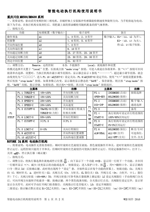
智能电动执行机构使用说明书重庆川仪M8500/M8600系列一、简要说明:驱动采用变频控制三相电机,在蜗杆轴上安装脉冲传感器能检测速度和旋转方向,当手轮抬起为电动,放下为手动。
在执行机构安装到位后,须把最上面的排油螺栓用随机配备的排气塞替换。
三、调整方法: Remote :远程控制 O/S :不能操作 Local :就地操作和设置将模式选择开关置于“Local ”位置,长按或点按“mode/stop ”按钮,可进入或退出各级菜单,按“+/-”按钮可在同级菜单内选择。
设置时,当执行机构在最小调节范围内,显示器会显示4条线“————”,超过最小调节范围,就会由线变化为“□□□□”。
进入P1.10(ADJUST-C )设定关向,P1.9(ADJUST-O)设定开向,使用“+/-”按钮设置新参数,然后短按“stop/mode ”按钮,如果参数已改变,显示器将显示静态的“SAVE ”,保存新值,则点按“stop/mode ”按钮,“SAVE ”闪烁,指示存储,如要取消,则点按+/-按钮,再点按“stop/mode ”按钮返回。
一、简要说明:电动操作无需检查相位,顺时针旋转红色旋钮至就地,黑色旋钮操作开和关,逆时针旋转红色旋钮则停止运行。
远程控制只能用于开和关,但顺时针旋转红色旋钮仍可使执行器停止运行。
用设定器操作时≡:打开Ⅰ:关闭 二、接线方式::向下显示下一个功能一行循环显示 +/-:减少/改变显示的功能或选项 。
初级设定:进入保护口令,按,用+/-翻转口令,显示正确的口令(默认Id )后按确认键。
此时将出现两个“设定”条,并始终显示在每个功能的屏幕上。
初级功能:C1:关阀方向(C :顺时针关,A :逆时针关)C2:关阀方式(Ct :力矩关,CL 限位关)C3:开阀方式(Ot :力矩开,OL:限位开)TC:关阀力矩值(40%-99%)TO :开阀力矩值(可参考执行器铭牌上额定值) LC 设定关阀限位(手动将阀门全关后,可向开阀方向旋转手轮最多一圈,按确认键,两个黑色线条闪烁,全关指示灯点亮,关阀限位设定完毕,显示屏显示全关符号。
3810L电动执行器使用说明中英文.

3810L电动执行器使用说明书3810L Electric Actuator Instructions目录Table of Contents1. 产品概述Product Overview2. 主要技术参数The main technical parameters3. 产品型号规格Product Specification4、结构与原理The structure and principles5、安装Installation6、调整Adjusting7、外形尺寸Dimension8、配套支架The supporting bracket9、故障和解决办法fault and solutions10 、订货须知Ordering Information 11 、安全使用注意事项Safety Precautions使用本执行器时,请先认真阅读和理解本说明书,通过正确的使用和维护,充分发挥其效能。
When using this actuator, please read and understand the present specification, by the proper use and maintenance, full play to its effectiveness.1 产品概述Product Overview3810L 系列直行程电子式电动执行器有以220V 交流单相电源和380V 三相交流电源两种驱动电源的机型,接受来自调节器控制信号( D C 4 ~ 20m A 或DC 1 ~ 5V ),实现预定直线往复运动的新型执行器。
本系列执行器被用作调节阀的执行机构时,几乎具备了调节阀本身所要求的各种动作变换功能以及阀开度信号功能和手动功能。
因此被广泛应于发电、冶金、石化、轻工及环保等工业部门。
主要特点:main feature:1.1执行器设计有伺服系统(无需另配伺服放大器),只需接入DC4〜20mA (或D C1~5V )信号和对应的电源即可工作。
博恩 BQ系列电动执行器选型手册说明书

BQ系列电动执行器选型手册BQ SERIES ELECTRIC ACTUATORINSTRUCTION AND MAINTENANCE MANUAL(BQ010—BQ300)浙江博恩自控阀门有限公司Zhejiang Theoborn Auto-Control Valves Co.,Ltd地址:温州经济技术开发区滨海园区三道四路119号ADD: No.119, 4th Road, 3rd Avenue, Binhai Industrial Zone, Economic & Technical, Wenzhou, China.电话(TEL):+86-577-86378000 86830000 传真(FAX):+86-577-86887882E-mail: *****************网站(Website):企业概况博恩自控阀门有限公司专门制造电动、气动执行器及各类阀门。
公司生产的自动化装置从根本上改变了传统上繁琐、复杂的阀门使用方法,将高科技融入阀门控制中,大大提高阀门使用效益,节省了大量的控制成本,给企业带来客观的效益。
浙江博恩自控阀门有限公司坐落在国内最具悠久泵阀制造历史的温州,公司借助当地悠久的泵阀业制造经验,结合精湛的生产工艺,加上博恩人独特的创新意识和严肃精神,努力将智慧发挥至极点,立志制造最好的产品,以之造福人类。
博恩人坚持以人为舟,以严肃为舵,以智慧为帆。
博恩人相信,凭借自己的专业技术,加上真诚的服务会征服客户,赢得客户,感动客户。
追求卓越 专注品质 加工中心装配与测试企业文化企业理念:以人为舟,以严肃为舵,以智慧为帆 质量方针:以人为本 科技创新 持续改进 创世界品牌 质量目标:(1)产品出厂合格率达到100% (2)在两年内顾客总满意率平均为98% 环境方针:遵纪守法 污染预防 节能降耗 清洁生产 安全方针:恪守法规 保障安全 预防为主 关爱健康注意:因技术、质量的不断升级改进,本手册内容若有修改,不再另行通知!简介BQ系列电动执行机构设计简洁、结构紧凑,适用于球阀、蝶阀、旋塞阀和各种90°旋转阀,用于阀门的启闭和调节,是对阀门实现远控、集控和自控的必不可少的驱动装置。
SQX STX INTELLI+系列 电动执行机构使用手册说明书

SQX & STX INTELLI+系列电动执行机构使用手册(ATEX & IECEx)N R 1179_r e v .06_C NSQX STX系列1 安全须知下列文档也应被参考:a)IEC/ E N60079-14 标准 (易爆气体环境下的电气安装),b)IEC/EN60079-17 标准 (危险区域内的检查与维护操作),c) 其它涉及必须安装执行机构的区域的法令、政府规定、法律、指令、标准、流程及其它文档。
伯纳德不对因不遵守规则的行为而引起的后果负责。
我们的执行机构设计可用于易爆环境:组别 II -类别 2 蒸汽、雾气或气体 (G) 或粉尘 (D)。
对于气体可使用在区域 1 或 2,对于粉尘可使用在区域 21 或 22 。
执行机构 CE 标识我们的设备符合 ATEX 2014/34/UE 指令要求执行机构 IECEx 标识我们的设备符合 IECEx 认证执行机构 INMETRO IEx 标识我们的设备符合 INMETRO IEx 认证请仔细检查铭牌上的标识与安装区域的易爆环境类型、环境温度及允许设备表面温度是否相符。
执行机构的安装与维护必须由合格的、经过培训和认证的人员实施。
1.1 标识ATEX隔爆 “d”IECEx 隔爆 “d”IEx 隔爆 “d”制造商名称与地址BERNARD CONTROLS 4 rue d’Arsonval 95505Gonesse FranceBERNARD CONTROLS 4 rue d’Arsonval 95505Gonesse FranceBERNARD CONTROLS 4 rue d’Arsonval 95505Gonesse France执行机构类型Type STX...Type STX...Type STX...序列号与生产年份99605 001 - 201199605 001 - 201199605 001 - 2011认证号码INERIS 10 ATEX 0045 XIECEx INE 10.0017XIEx 12-IEx0226X特定标识II 2 GDc T135°C 认可审核机构号码 0080气体标识Ex d IIB T4 Gb Ex d IIB T4 Gb Ex d IIB T4 Gb 粉尘标识Ex tb IIIC T135°C DbEx tb IIIC T135°C DbEx tb IIIC T135°C Db环境温度-20°C +70°C-20°C +70°C-20°C +70°C警告使用前请仔细阅读本文件1.2 安装区域执行机构为 2 类防爆设备,根据标识可以使用在下面的区域:EPL = 设备保护等级. b= 高等级气体 (G) 与粉尘 (D).区域 1 (气体)与 21(粉尘):在正常操作过程中可能会偶尔出现易爆环境。
SND-QDB智能型部分回转电动执行机构说明书

二、产品概述...................................................................................................................................................................... 2
七、手动和电动操作.......................................................................................................................................................... 5 7.1 手动操作..................................................................................................................................................................5 7.2 电动操作..................................................................................................................................................................5
海沃德工业产品公司EJM系列电动执行器说明书

HAYWARD INDUSTRIAL PRODUCTS INC. Array ONE HAYWARD INDUSTRIAL DRIVECLEMMONS, NC 27012PHONE (336)-712-9900 FAX (336) 712-9518WARNING: FAILURE TO FOLLOW THESE INSTRUCTIONSMAY RESULT IN SERIOUS INJURY OR DEATH.INSTRUCTION MANUAL FOR HAYWARD CONTROLS EJM SERIES ELECTRIC ACTUATORS (110, 220 or 24 VAC & 12 or 24 VDC) This Instruction manual contains important information regarding the installation, operation and troubleshooting of EJM Series Electronic Actuators. Please read these instructions carefullyand save them for future reference.DESCRIPTIONEJM Series Electric Actuators are designed to provide reliable and efficient operation of final control elements, such as 1/4 turn valves, with torque requirements up to 3500 inch pounds.EJM Series actuators are available as AC models with duty cycles of 25% or 75% and DC models with a 100% duty cycle.GENERAL TECHNICAL INFORMATIONEJM Series AC voltage actuators use a split phase motor which internally steps up the applied 115 AC voltage and feeds it back to the off terminal. For example, when 115 VAC power is applied at terminals 1 and 4, 230 volts will be fed back to terminal 3. This can create a problem for controllers with solid state outputs rated for less than 230 VAC. It is suggested that the “clean” contacts provided be used for solid state device feed back.Additionally, due to this feed back, multiple actuators cannot be wired in parallel, and individual leads (isolated contacts) must be run to each actuator.It is important to verify that the output torque of the actuator is appropriate for the torque requirements of the valve and that the actuator duty cycle is appropriate for the intended application.DUTY CYCLEExceeding the actuator's rated duty cycle may cause the thermal overload switch to temporarily shut off power to the motor. A 25% duty cycle means that for every operating cycle that the actuator is ON (to open or close the valve), the actuator must be OFF for a time equal to three operating cycles. For example, an operating cycle time of 5 seconds ON, it must be OFF for 15 seconds before it is again operated. A 75% duty cycle means that for every operating cycle that the actuator is ON, the actuator must be OFF for 1/3 of a cycle.TEMPERATURE LIMITSLow ambient temperatures: The minimum recommended ambient temperature is -23°F. Care should be used in selecting actuators for valves for services below 40 °F as lower temperatures can affect valve torque. Please consult factory for actuator sizing.High ambient temperatures: The maximum recommended ambient temperature is 140°F with the actuator shaded from direct sunlight.POWER REQUIREMENTSCurrent (Amp) 120VAC Current (Amp)220VACCurrent (Amp)240 VAC3 phaseModel TORQUE- IN/LBSSpeed90ºSecondsRun Stall Run Stall Run StallEJM2S2T 150 8 0.50.6 0.3 0.5EJM3S2T 300 12 0.50.6 0.3 0.5EJM8S2T 800 15 1.01.8 0.5 0.9 0.6 1.1 EJM13S2T 1300 22 1.0 1.8 0.5 0.9 0.6 1.1 EJM35S2T 3500 16 1.0 3.6 0.5 1.8 1.0 3.5Current (Amp) 12 VDC Current (Amp)24 VDCCurrent (Amp)24 VACModel TORQUE- IN/LBSSpeed90ºSecondsRun Stall Run Stall Run StallEJM2S2T 150 8 0.53.0 0.3 1.8 0.3 1.8EJM3S2T 300 12 0.5 3.0 0.3 1.8 0.3 1.8EJM8S2T 800 15 3.4 8.5 2.0 5.0 2.0 5.0EJM13S2T 1300 22 3.4 8.5 2.0 5.0 2.0 5.0EJM35S2T 3500 16 5.0 10 3.0 6.0 3.0 6.0 INSTALLATIONCAUTION: Dangerous voltages are present inside the actuator cover unless the power supply to the actuator has been shut off or disconnected. Use extreme caution whenever working on the actuator withthe cover removed.TOOLS REQUIRED: 1/16 inch hex wrenchSmall flat blade screwdriverPhilips head screwdriverMOUNTING THE ACTUATORThe actuator may be mounted in any position. In outdoor applications the actuator should not be installed upside down.It is mandatory that the actuator be firmly secured to a sturdy mounting bracket. A minimum of four bolts with lock washers; should be used to secure the actuator to the bracket. Flexibility in the bracket is not allowed, and backlash, or "play", in the coupling should be minimized. The actuator output shaft must be in line (centered) with the valve shaft to avoid side-loading the shaft.WIRINGFor 115 VAC actuators, 18 or 20 gauge wire may be used for short runs. At least 16 gauge wire is recommended for longer runs. Be sure to follow local wiring codes.To operate an electric actuator, power (which may be 24, 115, or 230 VAC dependent on the actuator - please match before wiring as the wrong voltage will destroy the motherboard) from the user is wired directly to the actuator's motor through two limit switches. The limit switches control the actuators mechanical travel limits, usually 90 degrees.To drive the actuator counterclockwise (CCW), apply power to terminals 1 and 3. To drive the actuator clockwise, apply power to terminals 1 and 4. The actuator can be driven fully open (CCW) or closed (CW) by maintaining power to the motor until the actuator trips the internal limit switches. Power can also be disconnected at any point during travel to position the actuator.WATERTIGHT ACTUATORS are not watertight until final installation is complete with conduit entry sealed and actuator cover in place.MODULATING CONTROL BOARD SETUPDIP Switch SettingsDisconnect power from unit when making the following DIP Switch adjustments.Input Signal: • For 4-20 mA, set 1 “on ” and 2 “off ” • For 1-5 Vdc, set 1 “off ” and 2 “off ”• For 2-10 Vdc, set 1 “off ” and 2 “on ”Ouput Signal:• For 4-20 mA, set 3 “off ”, 4 “on” and 5 “off ” • For 2-10 Vdc, set 3 “on ”, 4 “off” and 5 “on ” Fully Open:• For the valve to be fully open with an input signal of4 mA, 1 Vdc or 2 Vdc; and the valve to be fully closed with the input signal of 20 mA,5 Vdc, or 10 Vdc, (Increasing signal closes) –set6 “on” • For the valve to be fully closed with an input signal of 4 mA, 1 Vdc or 2 Vdc; and the valve to be fully open with an the input signal of 20 mA, 5 Vdc, or 10 Vdc, (Increasing signal opens) –set 6 “off”Loss of Signal (LOS)• Valve “closes” fully on LOS, set 7 “off ” and 8 “on ”• Valve “opens” fully on LOS, set 7 “on ” and 8 “off ”• Valve locks in place on LOS, set 7 “on ” and 8 “on ”Deadband Setting• Adjust SW1 clockwise to increase deadband.•Adjust SW1 counterclockwise to decrease deadband.DeadbandDIP SwitchesWIRING DIAGRAMSCAUTION: Dangerous voltages are present inside the actuator cover unless the power supply to the actuator has been shut off or disconnected. Use extreme caution whenever working on the actuator withthe cover removed.ADJUSTMENT OF LIMIT SWITCHESThe two limit switches operating off the cams on the output shaft determine the exact positions where the actuator will stop at the end of each cycle. The first limit switch (lowest) determines the OPEN position (CCW rotation). The second limit switch (from bottom) determines the CLOSED position (CW rotation). The limit switches can be adjusted from5 to 320 degrees of actuator rotation. If an adjustment of any of the positions is required, proceed as follows:A. Remove Actuator CoverRemove the actuator cover by removing the screws securing the cover to the base.B. Adjust the OPEN limit switch cam1. Using a 1/16 hex wrench, loosen the setscrew in the OPEN limit switch cam (the bottom switch).2. Apply power to terminals 1 and 3 (See Figures 3) to drive the actuator to the open position (counterclockwiserotation).3. Remove the power from the actuator.4. Rotate the cam toward the limit switch arm just until the switch clicks closed.5. Re-tighten the setscrew on the limit switch cam (Be careful not to over-tighten the screw).C. Adjust the CLOSED limit switch cam1. Using a 1/16 inch hex wrench, loosen the set screw in the CLOSED limit switch cam (the second from thebottom).2. Apply power to terminals 1 and 4 (See Figures 3) to drive the actuator to the closed position (clockwise rotation).3. Remove the power from the actuator.4. Rotate the cam toward the limit switch arm just until the switch clicks closed.5. Re-tighten the setscrew on the limit switch cam (Be careful not to over-tighten the screw).STANDARD ADDITIONAL LIMIT SWITCH WIRINGThe actuator's travel limit switches may be used to indicate the open and closed status of the actuator. Power at terminal 3 is switched to terminal 5 when the actuator is fully CCW. Power at terminal 4 is switched to terminal 6 when the actuator is fully CW. Two “Additional” limit switches are provided to allow “clean” contact closure at the end of travel. They are adjusted utilizing the above procedure with the top switch as the closed switch and the second from the top the open switch.TROUBLESHOOTING GUIDECAUSE REMEDY TROUBLE POSSIBLENo Power to actuator Check source, fuses, wiringMotor burned out Replace motor and determine cause offailureMotor does not operateThermal overloaded, (Over heated) Wait for motor to cool down and reset.Actuator output shaft stalled Check drive load for mechanical jamand correct causePower Supply short circuit Check wiringMotor stops runningJammed, damaged power gearing Repair gearingObject caught in valve Check and clean valveTraveling cam screw loose or out of position. Reset cam and Tighten screwNot able to fully open or closeDistortion of mounting or valve stem. Replace valve stemBroken or worn power gearing. Repair power gearingMotor runs, but output shaft doesnot rotateValve stops operating while motorWorn out gear Replace gearis running Worn or broken actuator to valve coupling Replace couplingIf the actuator fails to operate:Check that the proper voltages are present at the actuator's terminal connections.If the motor is hot the actuator may have gone in to thermal over load protection (the motors are equipped withinternal thermal overload protection). Let the motor cool and check the following:Are the limit switches properly set?Is the actuator's duty cycle correct for the application?Is the actuator's output torque within the required range?If the actuator's motor hums or turns slowly:Check the actuators motor capacitor to see if it is broken or cracked.Make sure power is applied only to one terminal, either 3 or 4 but not both.Check for a bad connection at motor socket S3.。
沃士特电动执行器系列75 型号WCABR1014 (部件 PB 730) 手册说明书
AN ISO 9001 REGISTERED COMPANYon/off and modulatingFlow Control Division Worcester Actuation SystemsSeries 75 Electric Actuators from Worcester Actuation Systems add a new dimension of operational dependability and flexibility to modern processes controlled by computers, programmable controllers and other electric control equipment. A multi-function capability permits use of the Series 75 actuator throughout the process for on/off, throttling, variable-cycle and any analog or digital control. One of the most reliable electric actuators on the market, the Series 75 is lightweight, compact and powerful. Its split phase capacitor AC reversing motor or DC motor drives a valve through a sealed, permanently lubricated gear train which offers virtually lifetime maintenance-free dependable operation.The Series 75 is available in eight sizes and produces torques to 3000 in-lbs. Housings are designed to TYPE 1 General Purpose, TYPE 4Watertight, and TYPE 7, Class 1, Division 1 and 2, Group C, D and TYPE 9, Class II, Division 1 and 2, Group E, F, G. A combined location TYPE 4, 4X, 7, 9 enclosure is also available as a “Z” option. A baked polyester finish is the standard coating, but special coatings are avail-able for extreme hazardous-environment applications.Series 75 actuators may be used on Worcester Controls complete line of ball valves, other quarter-turn valves or devices requiring rotary operators. Moreover, their ability to provide power in both directions through selected arcs from 20°through 300°makes them ideal for control of heating, ventilating and air conditioning duct systems and automatic, remotely operated equipment.Worcester Controls Series 75A time-tested, high-quality state-of-the-art electric actuator for remote control of quarter-turn valves andother rotary devices. Simple, compact and reliable.2WCABR1014Flow Control DivisionWorcester Actuation Systems Options to Fit Your ApplicationsThe Series 75 can be ordered with a variety of options to tailor it tothe needs of your application.Cycle Length Control– This speed control feature allows field adjust-ment of opening and closing cycle times, 19 minutes for 25% dutyand 57 minutes for 75% duty actuators.Feedback (0-1000 ohm) Potentiometer– provides a variable resis-tance to signal the exact position of the output shaft and the valve itis powering.Position Indicator Board– provides a 4-20 mA valve position feedbacksignal to the control room.Heater/Thermostat – prevents condensation from collecting inside theactuator.Condensation Drain Plug– drains accumulated water.180°Center-Off Kit – provides an extra position for three-way valvesand is used for dribble-feed applications in quarter-turn valves.Additional Limit Switches– may be used to operate lights that indi-cate valve position or to operate other equipment.AF-17 Positioner Board– for control valves positions the actuatorbased on an input signal of current, voltage or resistance.DFP17 DataFlo P™– is a microprocessor-controlled electronic posi-tioner with software for on-site or remote operation and diagnostics.This new, smart positioner for Series 75 actuator driven controlvalves is controlled by a 4-20 mA analog signal from a PLC or digital-ly from a computer.DFC17 DataFlo C™– is a microprocessor based PID single-loop con-troller that accepts a variety of process inputs. All process parametersare easily programmed through the keypad or via a simple RS-485computer interface.I 75 Low-Current Circuit Interface– is a solid-state interface/relaybetween the PC/controller/computer and actuator motor(s). It pro-tects controlling device outputs from destructive feedback. Thishigh-voltage feedback is due to limit switch action, auto transformereffect of unused winding, and capacitor voltage. The unit, as a printedcircuit board, is conveniently mounted inside of standard enclosures.Maximum output ratings are 4 A for 120 VAC and 2 A for 240 VAC.Controllers with outputs that have low current ratings cannot be con-nected to electric actuator motor(s) that require a current greater thanthe controller rating.R 75 Remote Terminal Unit(RTU) – is an interface for DC powered actuators. This solid-state interface card allows you to control a DC-powered electric actuator by a control signal from the Remote Terminal or any low current system (such as a solar powered sys-tem). It is equipped with a field-adjustable current limiting circuit, which will trip the power in case of abnormal conditions (it will reset by reengaging the control signal). Optional contact closure to indicate the tripped condition; 0-5 VDC, 0-1000 ohm position feedback, and end of travel SPDT gold contact switches are available.DFP17 Positioner for ControlValvesTYPE 1Sizes 10, 12, 15, 20, 22(Enclosure Option – Blank)Combined TYPE 4, 7 & 9Sizes 25, 30(Enclosure – Z)Combined TYPE 4, 4X, 7 & 9Sizes 10, 12, 15, 20, 22, 23(Enclosure Option – Z)TYPE 4Sizes 10, 12, 15, 20, 22(Enclosure Option – W)TYPE 7 & 9Sizes 10, 12, 15, 20, 22(Enclosure Option – X)WCABR10143Sizes:Small: 10, 12, 15, 20, 22, 23 Large: 25, 30Torque:150-3000 in-lbs.Enclosures:TYPE 1 General Purpose TYPE 4 WatertightTYPE 7, Class I, Division 1, 2,Group C, DTYPE 9, Class II, Division 1, 2,Group E, F, G Hazardous LocationsTYPE 4, 4X, 7, & 9 CombinedLocations Enclosure Coatings: Corrosion resistant baked polyester finish standard. Consult Flowserve for special applications.Voltages:120 V and 240 VAC, 12 V and 24 VDCConnection:Male output shaft (female shaft available on request)Gearing:Small: Sealed, permanently lubri-cated spur gear module driving a final dual-torque bull gearLarge: Two-stage planetary gear,permanently lubricated self-lock-ing gear trainOverload Protection:AC only. Thermal overload pro-tector with automatic reset.Travel Stop Limit Switches: Two SPDT, all sizes; internal,independent, adjustable.Actuated by cams mounted on drive shaft. Adjustable from 20°to 300°.Manual Override:All sizes, TYPE 4, 7 and 9 only. Lift position indicator and turnshaft: Sizes 10,12,15, 20,22, 23.Turn side-mounted handwheel:Sizes 25 and 30.rotation.4WCABR1014Flow Control DivisionWorcester Actuation SystemsSpecificationsWCABR10145Flow Control DivisionWorcester Actuation SystemsDimensions inches (mm)Sizes 10, 12, 15, 20, 22TYPE 1 (General Purpose)Sizes 10, 12,15, 20, 22, 23TYPE 4 (Watertight) Enclosure - W,TYPE 7 & 9 (Hazardous Locations) Enclosure - X, TYPE 4, 7 & 9 (Combined) Enclosure - Z (shown)Sizes 25, 30TYPE 4 (Watertight) andTYPE 7 & 9 (Hazardous Locations) Combined Enclosure - Z(4 HOLES)1/4" - 20 UNC TAP x .38 (9.7) DEEP(4 HOLES)3/4 "NPT 1 Optional 1/2 " NPT 1/2" NPT Cover Removal Allowance: 6.27 inches min.( 4 HOLES)MOUNTING PATTERN1/4" - 20 UNC TAP x .38 (9.7) DEEP1/2"Main A Type 1, Sizes 10, 12, 15, 20, 22All other types and sizes6WCABR1014Flow Control DivisionWorcester Actuation SystemsWiring DiagramsSizes 10-30 AC PowerIMPORTANT!EACH ACTUATOR SHOULD BE ELECTRICAL-LY POWERED THROUGH ITS OWNINDIVIDUAL SINGLE-POLE SWITCH CON-TACTS TO ISOLATE THE UNUSED WINDING.NOTE: ACTUATOR SHOWN IN COUNTER-CLOCKWISE EXTREME OF TRAVEL, OR "OPEN" POSITION.Sizes 10-23 DC PowerNOTE: AC and DC wiring diagrams shown are for W, X and Z enclosures only. DCwiring diagram shown is for size 10, 20 and 23 actuators. For size 12 and 22 actuators,the red/black motor leads are reversed.Design OptionsA mechanical brake is used for all butterfly valve applications or when the actuator must be stopped instantaneously and securely. (Used on 10-23 sizes only.)Available for AC actuators only.Prevents destructive pipeline shock caused by fast opening or closing valves on steam or hydraulic service. The CLC units allow field adjustment of the standard actuator’s cycle time up to approximately 19 minutes for 25%duty and 57 minutes for 75% duty actuators.Additional Options Available. Consult Flowserve.NOTE:A 2" CPT valve should not be sized with an electric actuator smaller than 2275, and a mechanical brake must be ordered.May be mounted to either operate lights,indicate valve position, or operate other equipment such as pumps, compres-sors, mixers, etc.Heater/Thermostat180°Center-off (three positions)Mechanical BrakeA feedbackpotentiometer is used when remote indication is desired.Potentiometers are available in 1000 ohms.A heater/thermostat kit for cold ambient temperatures or humid environments uses a 15-watt heater and a ther-mostat set to close at temperatures below 70°F ambient.Used with three-way valves or similar products requiring a mid-position stop capability for shutoff. May be adjusted for travel other than 180°.NOTE: A three-posi-tion switch is required for operation.Feedback PotentiometerCycle Length Control (CLC)Limit SwitchesOne Limit Switch Two Limit SwitchesWCABR10147Sizes 25, 30Sizes 25, 30Sizes 10-23Item Qty.DescriptionMaterial11Base Aluminum Casting 21Cover Aluminum Casting 31Base Plate Zinc Casting 41Motor Module Zinc Casting 51Output Shaft Steel 62Gear Drive Pin Steel 71Bull GearSteel81Capacitor (w/Fiber Phenolic Encapsulated Washer if Required)91Capacitor Bracket Steel101Terminal Strip Polyethylene Based Material 112Limit SwitchPhenolic Encapsulated 122Limit Switch Cam Zinc Casting 131/Cam Cam Set Screw Steel 144Limit Switch Screw Steel 156Base Plate Screw Steel168Hex Screw (W,X,Z)Stainless SteelItem Qty.DescriptionMaterial164Hex Screw (GP)Steel171Position Indicator (W,X,Z)Molded Phenolic 181Indicator Set Screw (W,X,Z)Steel191Seal (W,X,Z)Reinforced Rubber 201Gasket (W only)Neoprene 201Flange Seal (Z only)Buna N 211Bearing Bronze221Seal Reinforced Nitrile 234ScrewSteel 244Lock Washer Steel251Conduit Plug Polyethylene 261Capacitor Tie Plastic 271Bearing (W, X, Z)Bronze 281Roller Bearing (size 23 only)Steel 291Bearing, Base Plate Nylon 301O-Ring (W, X, Z)Buna 312Insulator (not shown)NylonItem Qty.DescriptionMaterial11Base Aluminum 21CoverAluminum 31Gear Train Support Aluminum 41Motor51Output Gear Steel Casting 62Planet Gear Hardened Steel 71Planetary Gear Ductile Iron 81Worm Gear Steel 91Sensing Shaft Steel 102Pin, Spring Steel112Shaft Hardened Steel 122BushingBronze 132Thrust Washer Steel 141Pin, SpringSteel 154Belleville Washer Steel 161Nut Steel172SealRubber, Steel 181Manual Override Shaft Steel 191Pin, Cotter Steel 201Pin, SpringSteel211Handwheel, Manual Override Aluminum 221Thrust Washer Steel 231Tru-arc Ring Steel241Seal Rubber, Steel 251Sun Gear Steel 261Bushing Bronze 274Cap ScrewSteelItem Qty.DescriptionMaterial284Lock WasherSteel291Capacitor (w/Fiber Washer Phenolic Encapsulated if Required)301Input Gear Steel 311NutSteel 321Cap ScrewSteel331Position Indicator Aluminum 341BushingBronze 351Motor Support Plate Aluminum 361Gear, Pinion Steel 372Set Screw Steel381Terminal Strip Polyethylene Based Material 392Limit Switch Cam Zinc Casting 401/Cam Cam Set Screw Steel 411FanPlastic422Limit Switches Phenolic Encapsulated 431O-Ring Buna 449Cap Screw Steel 459Lock Washer Steel 4612Cap ScrewSteel 471Sensing Shaft Ret. Ring Steel481Conduit Plug Polyethylene 491Capacitor Bracket Steel 501Capacitor TiePlastic 511Capacitor Bracket ScrewSteelSizes 10-23How to Order*1575 can only be ordered with a 20% duty 120 VAC motor. The 2375 can only be ordered with a 75% duty motor.†† Specify operation in Option Operation column for CLC.† 120 and 240 VAC actuators will operate on 50 Hz. Torque will remain the same, cycle time will increase by a factor of 1.2 and duty cycle will be reduced by a factor of approximately 20%. **These options must be ordered as a separate item in addition to being specified in the actuator code.***Can only be ordered with a 75% duty motor.NOTE: TYPE 7, 9, (X) UL approved units are available on request. TYPE 4, 7, 9, (X, W, Z) are furnished CSA Approved.Due to continuous development of our product range, we reserve the right to alter the product specifications contained in this brochure as required.Flowserve Corporation has established industry leadership in the design and manufacture of its products. When properly selected, this Flowserve product is designed to perform its intended function safely during its useful life. However, the purchaser or user of Flowserve products should be aware that Flowserve products might be used in numerous applications under a wide variety of industrial service conditions. Although Flowserve can (and often does) provide general guidelines, it cannot provide specific data and warnings for all possible applications. The purchaser/user must therefore assume the ultimate responsibility for the proper sizing and selection, installation, operation, and maintenance of Flowserve products. The purchaser/user should read and understand the Installation Operation Maintenance (IOM) instructions included with the product, and train its employees and contractors in the safe use of Flowserve products in connection with the specific application.While the information and specifications contained in this literature are believed to be accurate, they are supplied for informative purposes only and should not be considered certified or as a guarantee of satisfactory results by reliance thereon. Nothing contained herein is to be construed as a warranty or guarantee, express or implied, regarding any matter with respect to this product. Because Flowserve is continually improving and upgrading its product design, the specifications, dimensions and information contained herein are subject to change without notice. Should any question arise concerning these provisions, the purchaser/user should contact Flowserve Corporation at any one of its worldwide operations or offices.For more information about Flowserve Corporation, contact or call USA 1-800-225-6989.FLOWSERVE CORPORATIONFLOW CONTROL DIVISIONWorcester Actuation Systems5114 Woodall RoadP.O. Box 11318Lynchburg, VA 24506-1318Phone: 434 528 4400Facsimile: 434 845 9736Printed in USA 11/03© 2003 Flowserve Corporation, Irving, Texas, USA. Flowserve and Worcester Controls are registered trademarks of Flowserve Corporation.WCABR1014 (Part PB 730)。
智能SCHIEBEL调试说明书 西贝执行器
智能SCHIEBEL调试文件智能SCHIEBEL是具有SMARTCON控制单元的智能型执行机构,它通过参数设置和内部程序控制,能有效增强控制的灵活性和舒适性,通过良好的人机界面交流,能最大限度发挥操作的简易性,它所具有的强大功能是其它执行机构所无法比拟的。
下面是对智能SCHIEBEL操作的简要介绍以及调试说明,供用户参考。
一、 界面操作与LED提示灯介绍1. 界面与操作通过选择开关(红)可以选择三种不同的操作形式:OFF 停止L就地(LOCAL). 此时只有用操作开关才能操作执行机构动作.远程控制 (REMOTE). 此时执行机构的动作只接受系统来的信号,不受操作开关的手动控制.根据选择开关的位置,操作开关就能获得不同的功能:选择开关在“OFF”位置:操作开关被用来上、下翻动菜单,操作开关从中间旋向的方向,可用来观察数据记录状态(S项及H项),从中间旋向的方向可以观察参数菜单(P项)在菜单里,选择开关具有对实际输入的确认和取消的功能,选择开关15度的旋转可用来确认或取消参数项里的各种输入(如果要修改参数请注意将左下角的“edit”变为“save”才能修改,如果要确认参数请注意将“save”变为“edit”).如果在菜单中想快速返主界面,请将选择开关打到L位置即可。
选择开关在“REMOTE”位置这个状态是远程控制状态, 通过操作开关只可观察不同的数据记录,不能进行参数的设定选择开关在“LOCAL”位置操作开关被用来控制执行机构,既可以将开关置于机械保持位置使执行机构做持续运动,也可以通过小幅偏转使执行机构点动,.点动时操作开关都能通过弹簧回到中间位置2. LED 指示灯各指示灯不同状态所表示的含义名称 颜色 亮闪烁不亮L1 红 开 正在开启 没到开位 L2 绿 关 正在关闭 没到关位L3 黄 转矩正常 转矩故障 ---------------L4 黄就绪报警 故障二、 调试说明调试是在确定机械安装和电气连接正确无误后方可进行!产品在出厂之前,参数都已按基本要求设置完成,请不要随意更改。
施耐德-QZDQ说明书-2013
பைடு நூலகம்
录
一: 产品概况·····································································································································1 二: 工作环境······································································································································1 三: 型号表示方法······························································································································1 四: 通用安全说明······························································································································2 五: 运输和存储··································································································································2 六: 安装和连接··································································································································3 1、 执行机构与阀门的安装········································································································3 2、 电气连接································································································································3 七: 手动和电动操作··························································································································5 1、 手动操作································································································································5 2、 电动操作································································································································5 3、 现场/远控操作·······················································································································5 4、 现场阀位指示························································································································6 4.1 操作界面的组成·················································································································6 4.2 阀门打开、 关闭指示···········································································································6 八: 参数的设定和调试······················································································································7 1、 参数的设定和调试方法········································································································7 2、 “项目选择”页面的进入········································································································7 3、 参数设定································································································································8 3.1 行程参数设定·····················································································································8 3.1.1 行程关向参数设定··········································································································8 3.1.2 行程开向参数设定··········································································································9 3.2 开度参数、 4~20mA 模拟量信号设定···············································································9 3.3 力矩参数设定···················································································································10 3.3.1 关向力矩值设定············································································································10 3.3.2 开向力矩值设定············································································································10 3.4 远控方式设定···················································································································11 3.5 双速 (变速慢关) 功能设置·····························································································12 3.5.1 双速 (变速慢关) 起始点设置························································································12 3.5.2 双速 (变速慢关) 占空比设置·························································································13 3.6 中间行程设定···················································································································13 3.6.1 中 1 行程设定·················································································································13 3.6.2 中 2 行程设定·················································································································14
智能开关型电动执行器说明书
VESON-Ⅱ型电动执行器控制部件使用说明一、概述VESON-Ⅱ型电动执行控制器是一种智能型、一体化的开关型电动执行器(俗称电动头)控制部件。
VESON-Ⅱ具有丰富的自诊断与保护功能,以及行程方向、电机方向自调整等功能。
带有液晶显示的就地操作面板,提供了全中文的设置菜单及简明的操作指导。
运行中液晶显示器实时显示阀门位置、工作状态、故障原因等。
控制器提供了就地与远方可切换操作功能。
远方控制可采用无源接点,通过控制台按钮手动操作。
也可由控制系统的继电器接点或集电极开路门、电平、脉冲等DO信号驱动,因此可方便地与DCS、PLC、计算机或其它的控制仪表直接连接。
VESON-Ⅱ可输出阀门全开、全关的无源接点信号。
就地操作按钮可采用非通透式磁性按钮或红外遥控,以满足更高的防护等级要求。
二、主要功能1、就地操作功能通过就地操作面板的“开”、“关”、“停”三键实现对执行器的开、关、停操作。
2、远程操作功能远程控制可接入“开”、“关”两只按扭,或与DCS、PLC等控制系统通过两路DO(集电极开路门或24V电平、脉冲、继电器等)连接,实现对执行器的开、关、停操作。
3、自动调整电机转动方向设置完成后自动调整电机方向为需要的方向。
4、自动调整行程方向用户可任意指定执行器的开、关方向,无需改变任何接线。
5、电子全开、全关限位功能。
6、卡涩保护。
自动回退、前进三次,仍卡涩断电报警。
7、位置传感器故障报警及保护。
如果位置检测电位器发生故障,引线故障或位置检测电路故障,可自动停电机并点亮报警灯。
三、主要技术指标1、工作电源:AC60V~AC280V。
2、位置传感器:0~500Ω至0~10K电位器。
3、远方开、关控制信号:无源接点、集电极开路门:灌电流10mA。
电平、脉冲信号:24V,低电平有效,灌电流10mA。
4、阀门全开、全关接点信号:继电器常开接点。
接点容量5A/AC 250V;7A/DC30V。
5、工作环境温度:-25~70℃。
- 1、下载文档前请自行甄别文档内容的完整性,平台不提供额外的编辑、内容补充、找答案等附加服务。
- 2、"仅部分预览"的文档,不可在线预览部分如存在完整性等问题,可反馈申请退款(可完整预览的文档不适用该条件!)。
- 3、如文档侵犯您的权益,请联系客服反馈,我们会尽快为您处理(人工客服工作时间:9:00-18:30)。
stq40b型电动执行器说明书
1、功能强劲:智能型、比例式、开关式、各类信号输出型应有尽有。
2、体积小巧:体积仅相当于同类产品的35%左右。
3、轻便宜人:重量仅相当于同类产品的30%左右。
4、性能可靠:轴承牙口电器元件等关键零部件采用进口名牌产品。
5、美观大方:铝合金压铸外壳、精细流畅、且可减少电磁干扰。
6、精密耐磨:蜗轮输出轴一体化特殊铝合金锻造、强度高、耐磨性好。
7、回差极小:蜗轮输出轴一体化、避免了键联结的间隙、传动精度高。
8、安全保证:通过1500V耐压检测,F级绝缘电机,安全有保障。
9、配套简单:采用单相电源、外接线路特别简单,也可做380V、直流电源。
10、使用方便:免加油、免点检、防水防锈、任意角度安装。
11、保护装置:双重限位、过热保护、过载保护(选装)。
12、多种速度:全行程时间5秒、10秒、15秒、30秒、60秒、100秒等。
13、防腐防锈:支架、联轴器、螺钉均采用不锈钢。
14、智能数控:数字设定、数字整定、高度精确、自诊断、一机多能。
15、集成一体:智能控制模块高度集成于电动装置本体中,无须外接定位器等。